

Page 1
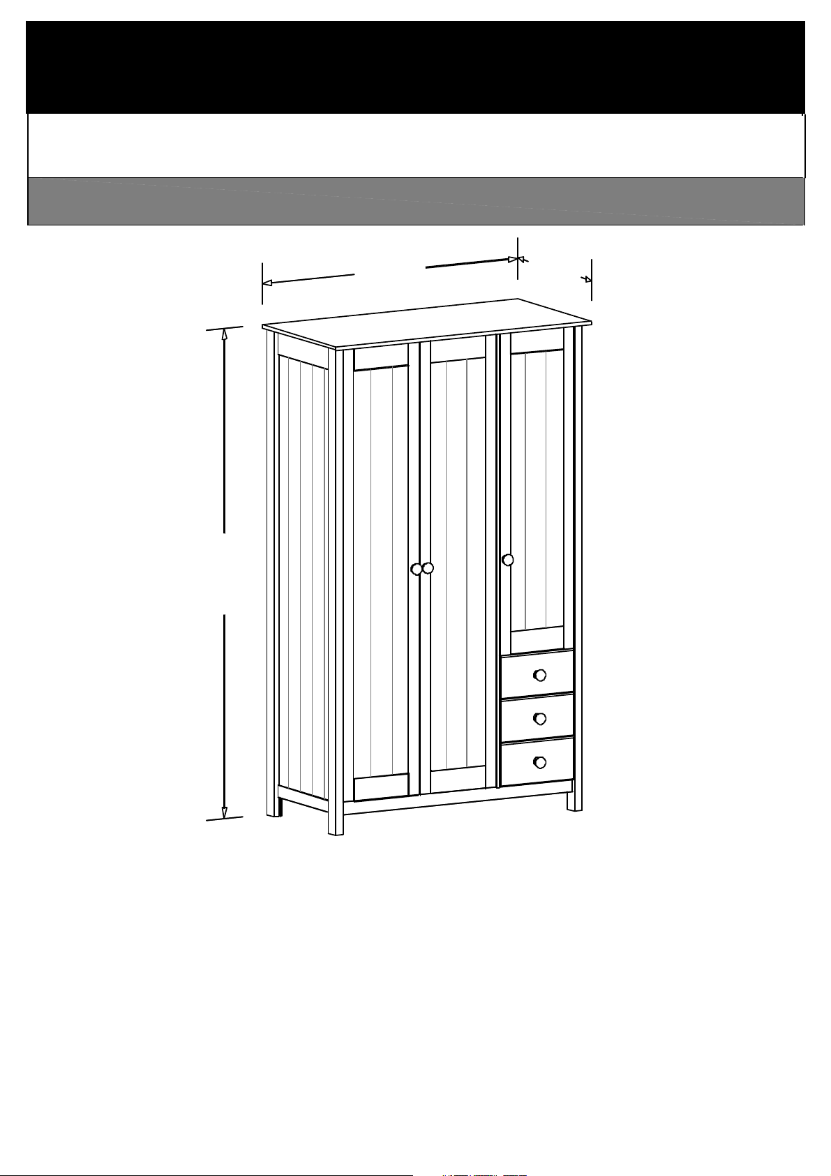
Scandinavia
2½ door robe w. 3 drws.
1799mm
1070mm
530mm
Page 1 of 26
2½ door robe w. 3 drws.
Page 2
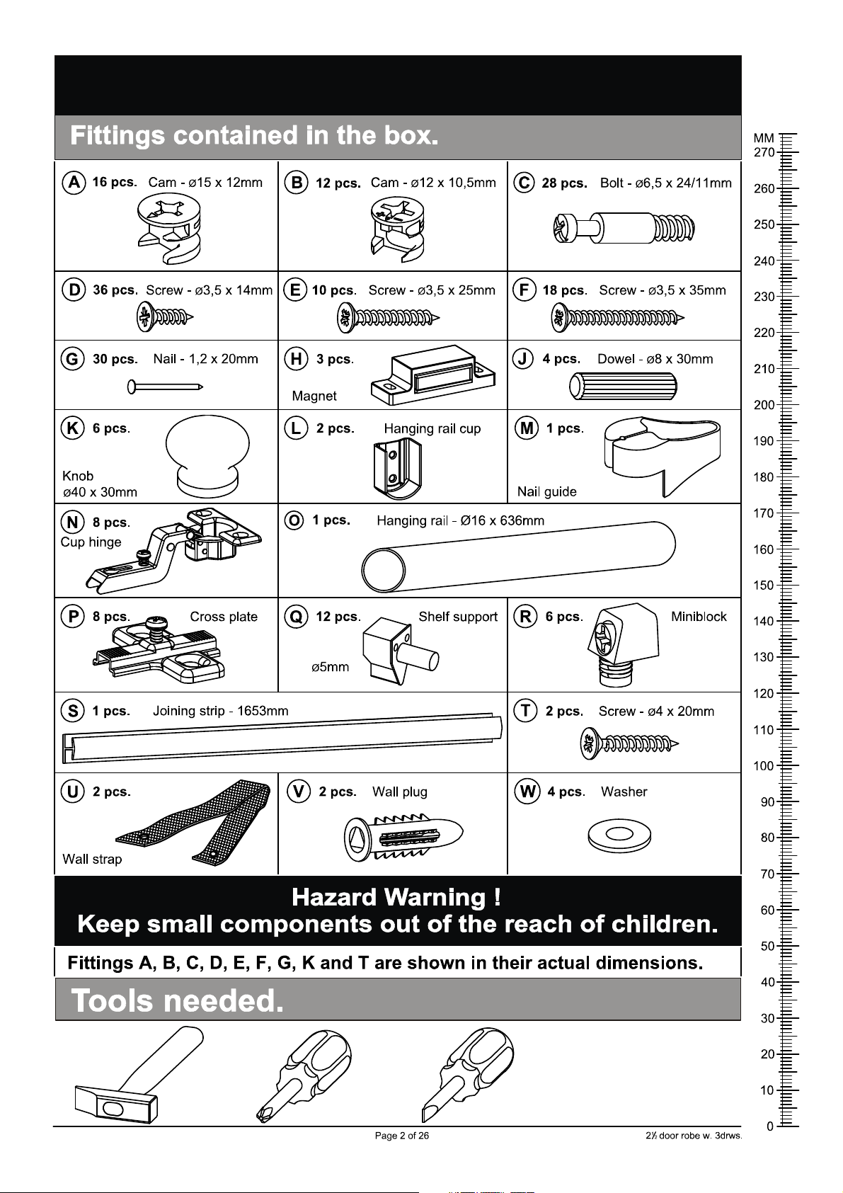
Please sort out all parts before you begin to assemble the item.
This to make sure you always use the correct part.
Page 3
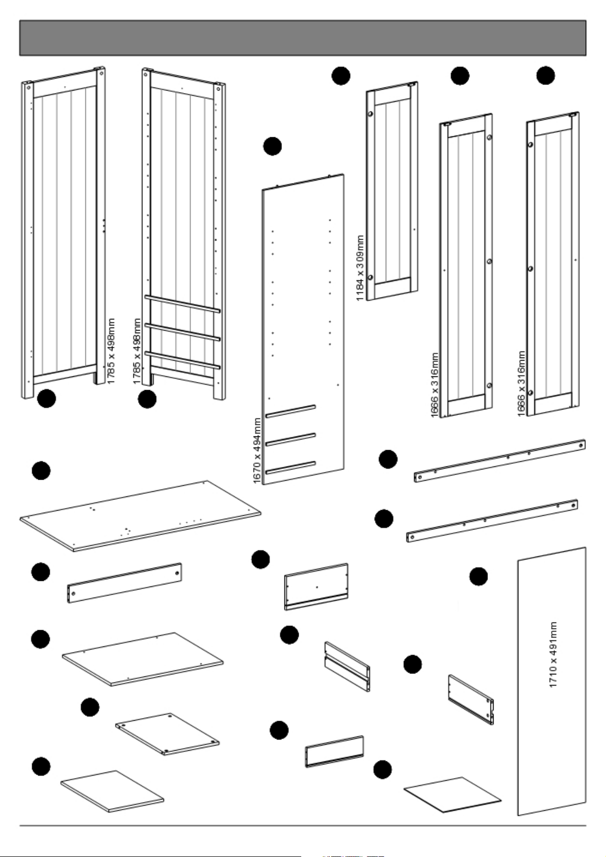
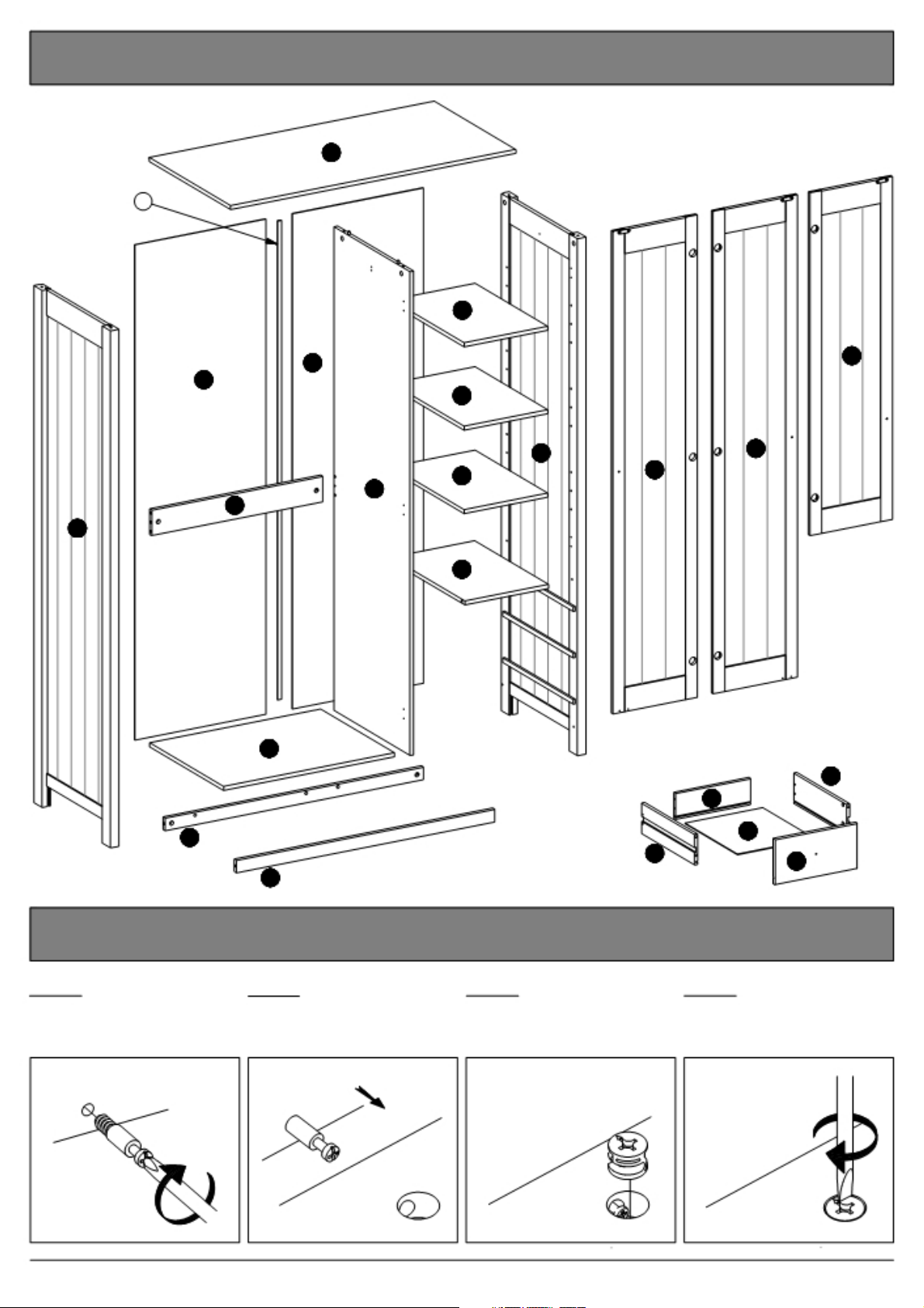
Wooden parts contained in the box.
3 Divider, large
1 pcs.
4 Door, small 5 Door, left
1 pcs. 1 pcs.
6 Door,
1 pcs. right
1 Side, left
1 pcs.
2 Side, right
1 pcs.
7 Top
1 pcs.
1070 x 530mm
8 Rail
1 pcs.
640 x 90mm
9 Bottom, large
1 pcs. 640 x 480mm
12 Plinth, back
1 pcs.
13 Plinth, front
1 pcs.
14 Drawerfront
3 pcs.
309 x 157mm
15 Drawer side, left
3 pcs.
342 x 107mm 3 pcs.
967 x 45mm
967 x 45mm
19 Back
2 pcs.
16 Drawer side, right
11 Shelf
3 pcs.
313 x 475mm
10 Bottom, small
1 pcs.
313 x 480mm
17 Drawerback
3 pcs.
281 x 92mm
Page 3 of 26
342 x 107mm
18 Drawer bottom
3 pcs.
291 x 339mm
2½ door robe w. 3 drws.
Page 4
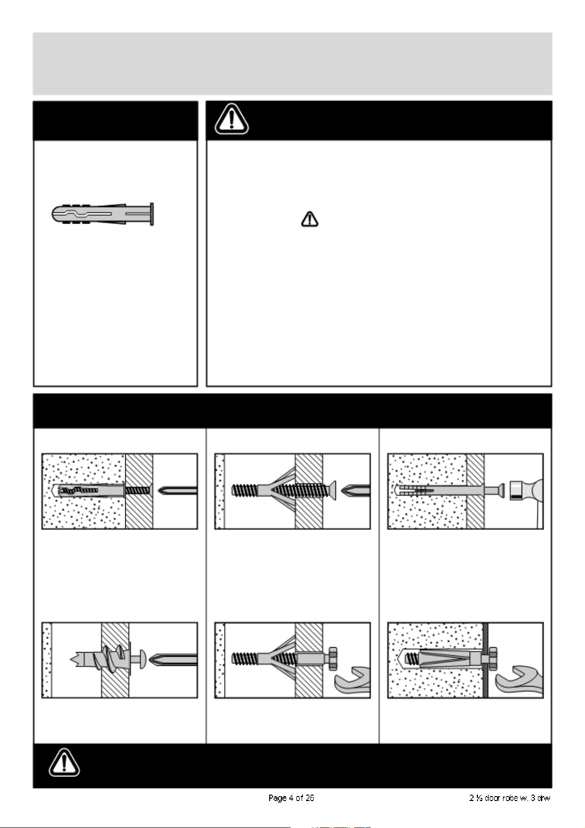
A Guide to - Wall Mounting & Fixings
Important note:
If plastic wall plugs
are supplied with your
product:
- these are only suitable for
use in masonry walls.
If you are in any doubt about
the correct wall plugs for
your wall, seek professional
advice.
Failure of the product due to
using incorrect fixings is the
responsibility of the installer.
Important:
When drilling into walls always
check that there are no hidden wires or pipes etc.
Make sure that the screws and wall plugs being used
are
suitable for supporting your unit. Consult a qualified
tradesperson if you are unsure.
Hints:
1: General rule:
if you are not sure.
2: Ensure you use the recommended drill bit to match the wall
plug and hole size.
3: Ensure you drill the hole horizontally, do not force the drill or
enlarge the hole.
4: Take extra care when drilling high walls, ceilings and ceramic
tiles. Ensure wall plugs are inserted beyond the thickness of
the ceramic tiles to avoid the tiles splitting or cracking.
5: Ensure wall plugs are well fitted and are a tight fit in the
drilled hole.
Always use a larger screw and wall plug
Types of walls
No.1 “General Purpose” wall plug No.3 “Cavity Fixing” wall plug
Generally aerated blocks should not
be used to support heavy loads, use
a specialist fitting in this case. For light
loads, general purpose wall plugs can
be used.
No.2 “Plasterboard” wall plug
You can use one of the following types of wall plug if your walls are made
of brick, breeze block, concrete, stone or wood.
For use with plasterboard partitions or
hollow wooden doors.
No.4 “Cavity Fixing-Heavy Duty”
wall plug
No.5 “Hammer Fixing”
For use with walls stuck
plasterboard. The hammer fixing allows
it to be fixed to the wall rather than the
plasterboard. Always check the fixing
is secure to the retaining wall.
No.6 “Shield Anchor” wall plug
Heavy loads
wall plug
with
For use when attaching light loads on
to plasterboard partitions.
Care &
Maintenance
For use when fitting or supporting
heavy loads such as shelving, wall
cabinets and coat racks.
Safety: Always check the fitting
and location to ensure your safety
in and around the home.
For use with heavier loads such as TV
& HiFi speakers and satelite dishes etc.
Fitting: From time to time check
the fitting to ensure the wall plugs
or screws do not become loose.
Page 5
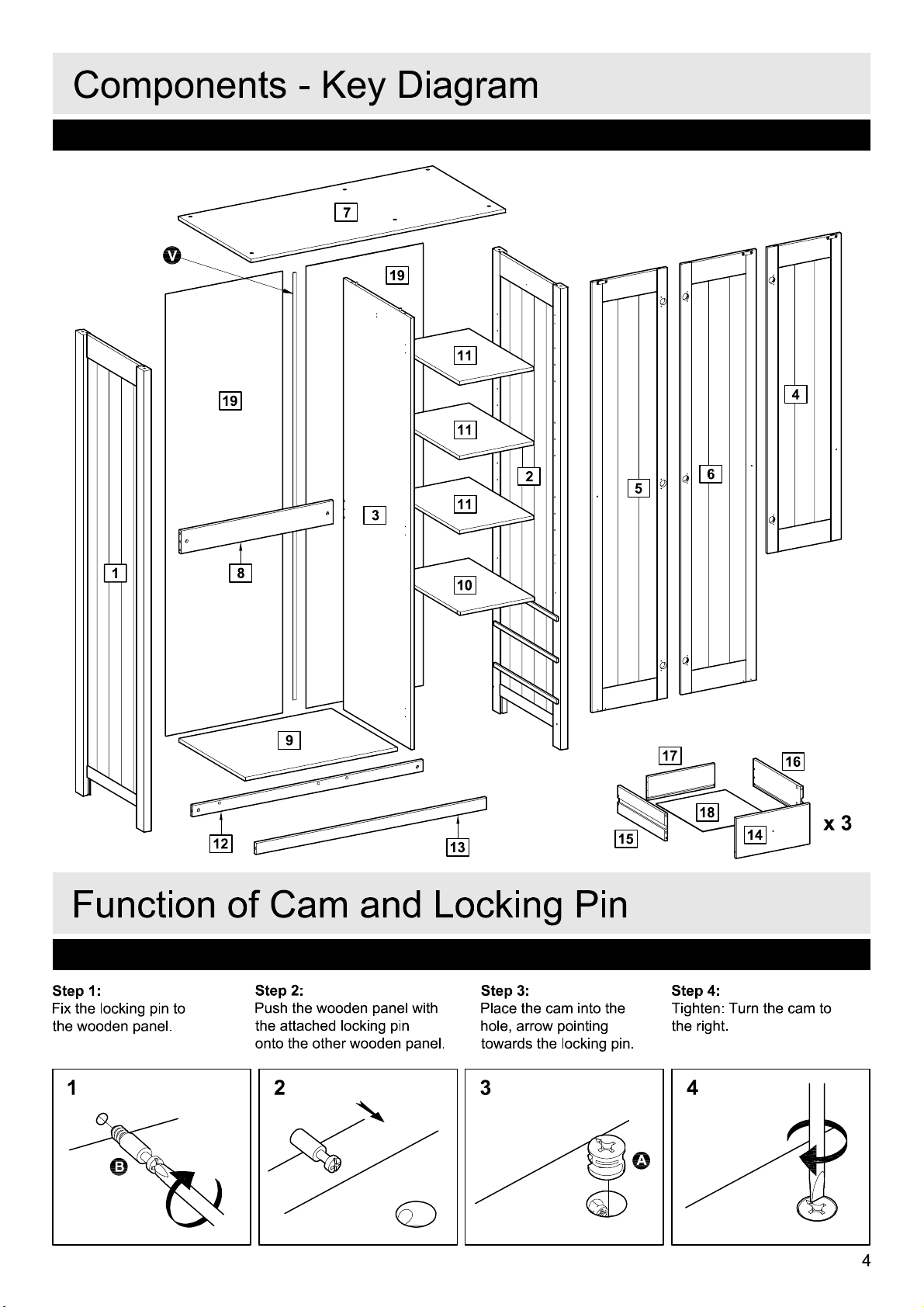
Key diagram.
S
7
11
19
19
11
2
3
11
8
1
10
9
5
17
6
4
16
12
15
13
18
x3
14
Function of cam & bolt.
Step 1: Step 2: Step 3: Step 4:
Fix the Bolt to the
wooden Panel.
Push the wooden Panel
with the attached Bolt onto Hole, arrow pointing the Right.
the other wooden Panel. towards the Bolt.
Place the Cam into the
1 2 3 4
Page 5 of 26
Tighten: Turn the Cam to
2½ door robe w. 3 drws.
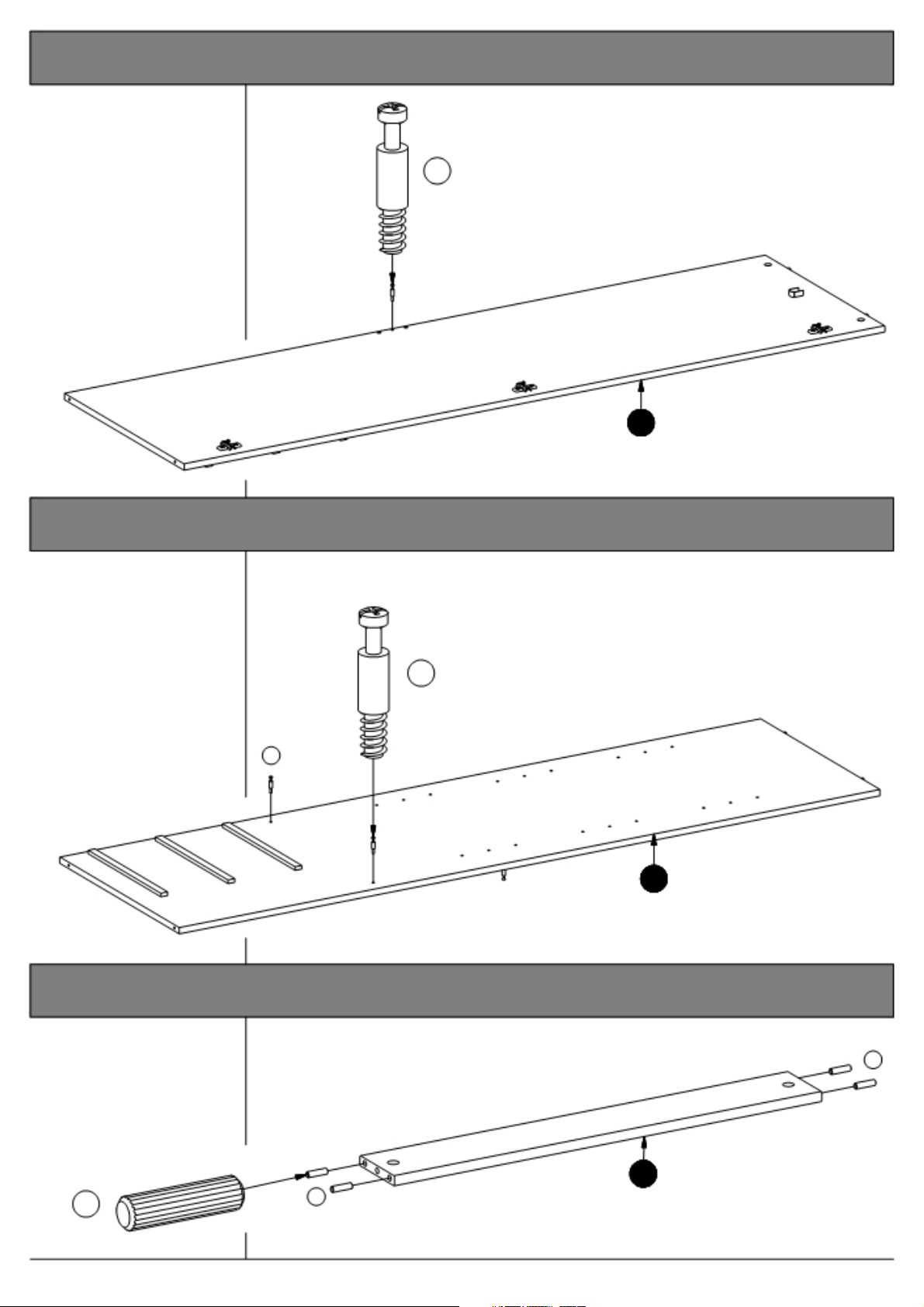
Page 6
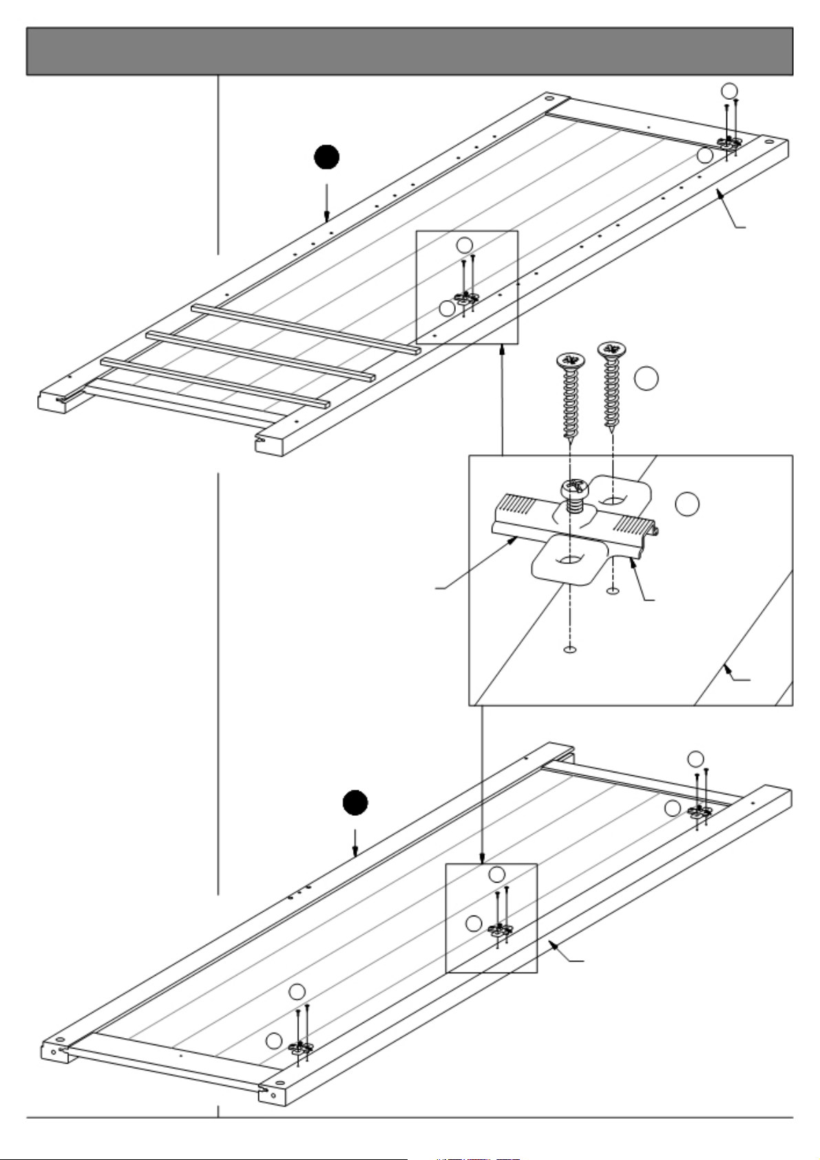
1. Mounting the cross plates to the sides.
Fix the cross plates "P"
to the sides "1" and "2"
using screws "E" into
the holes indicated.
2
Side, right
E
P
Front
E
P
E
10 Pcs.
Fig. 1.1
P
It is important that the
cross plates is placed
exactly as shown.
The short end of the
cross plates must point Short end
towards the front edge
of the sides.
See fig. 1.1
Long end
1
Side, left
E
5 Pcs.
E
P
Front
P
Front
E
P
Page 6 of 25
2½ door robe w. 3 drws.
Page 7
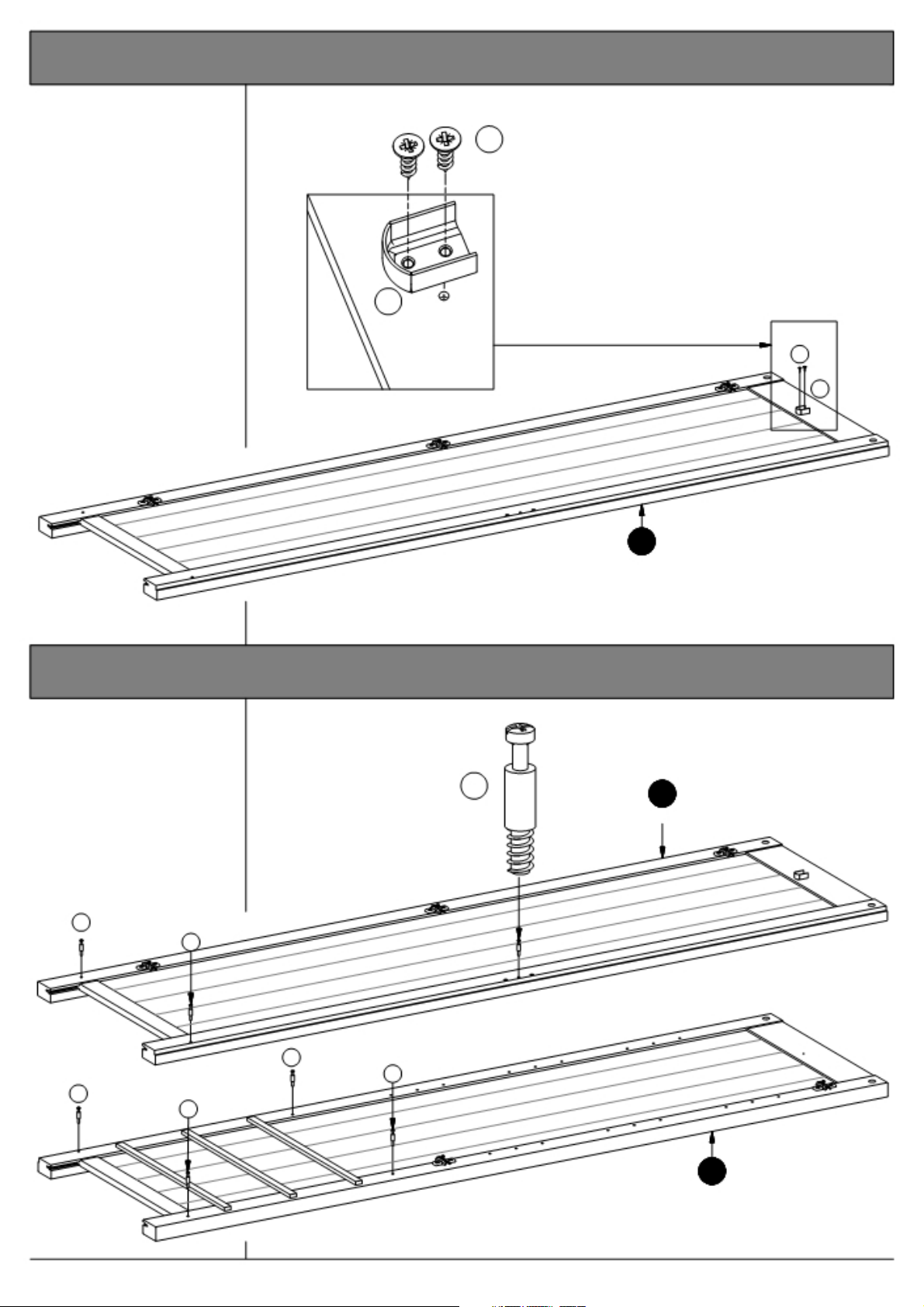
2. Mounting the hanging rail cup to the left hand side.
Fix the hanging rail cup
"L" onto the left hand
side "1" using screws
"D" into the pre-drilled
hole.
See fig. 2.1
L
1 Pcs.
Fig. 2.1
D
2 Pcs.
D
L
3. Mounting the bolts to the sides.
Screw the bolts "C"
into the holes
indicated on the sides
"1" and "2".
C 1
7 Pcs. Side, left
C
C
1
Side, left
C
C
C
C
2
Side, right
Page 7 of 26
2½ door robe w. 3 drws.
Page 8
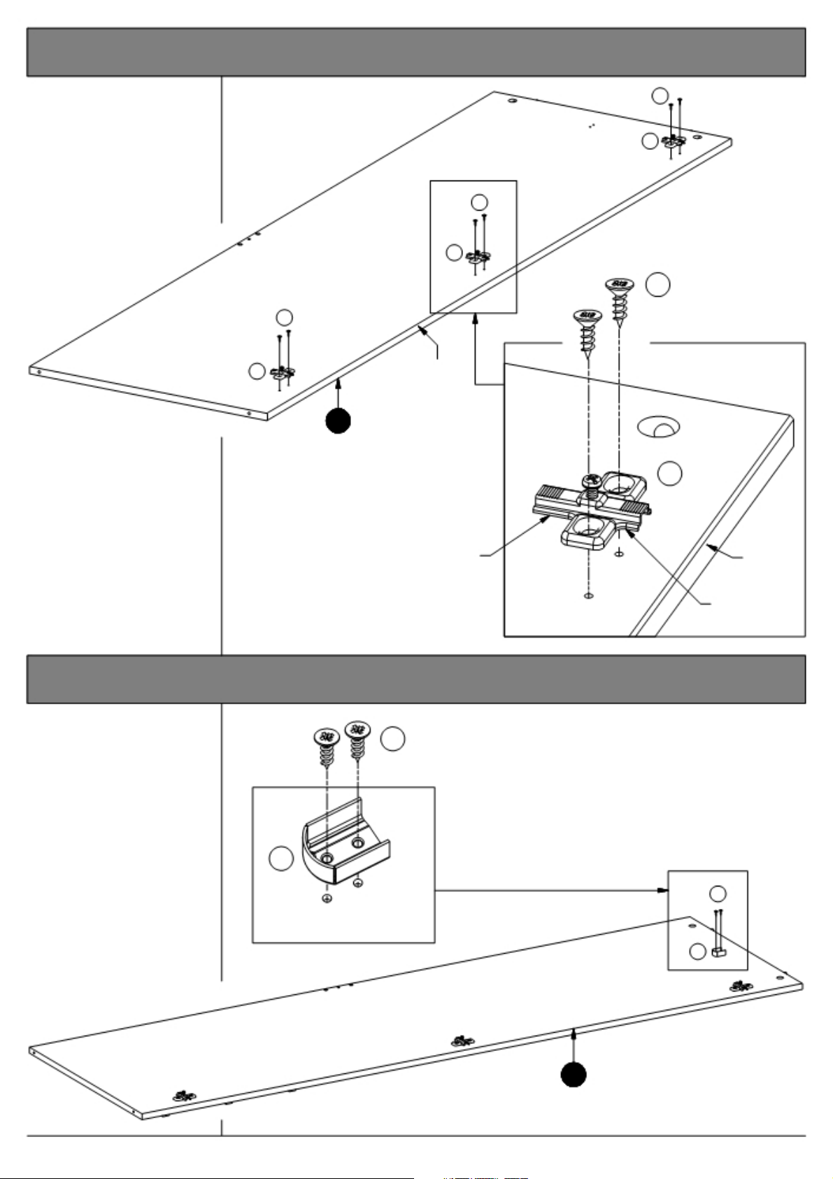
4. Mounting the cross plates to the divider.
Fix the cross plates "P"
to the divider "3" using
screws "D".
It is important that the
cross plates is placed
exactly as shown.
The short end of the
cross plates must point
towards the front edge of
the divider.
See fig. 4.1
D
P
D
P
D
6 Pcs.
D
Fig. 4.1
P Front
3
Divider
P
3 Pcs.
Long end
5. Mounting the hanging rail cup to the divider.
Fix the hanging rail cup
"L" onto the left hand
side of the divider "3"
using screws "D" into
the pre-drilled holes.
See fig. 5.1
L
1 Pcs.
Fig. 5.1
D
2 Pcs.
Front
Short end
D
L
Page 8 of 26
3
Divider
2½ door robe w. 3 drws.
Page 9
6. Mounting the bolts to the left hand side of the divider.
Screw the bolt "C" into
the hole indicated on
left hand side of the
divider "3".
C
1 Pcs.
3
Divider
7. Mounting the bolts to the right hand side of the divider.
Screw the bolts "C" into
the holes indicated on
right hand side of the
divider "3".
C
2 Pcs.
C
3
Divider
8. Adding the dowels to the rail.
Knock the dowels "J"
into the holes indicated
on the rail "8".
J
4 Pcs.
J
Page 9 of 26
J
8
Rail
2½ door robe w. 3 drws.
Page 10
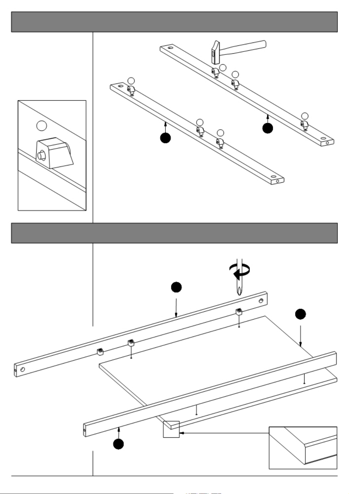
9. Adding the miniblocks to the plinths.
Knock the miniblocks
"R" into the holes
indicated on the plinths
"12" and "13".
R
R
Fig. 9.1
R
6 Pcs.
13 Plinth, back
Plinth, front
R
R
R
R
12
10. Mounting the plinths to the bottom.
Fix the plinths "12" and
"13" to the bottom "9"
using the screws in the
miniblocks "R".
The front plinth "13"
MUST be placed near the
chamfered edge of the
bottom.
See fig. 10.1
12
Plinth, back
9
Bottom, large
13
Plinth, front
Page 10 of 26
Fig. 10.1
2½ door robe w. 3 drws.
Page 11
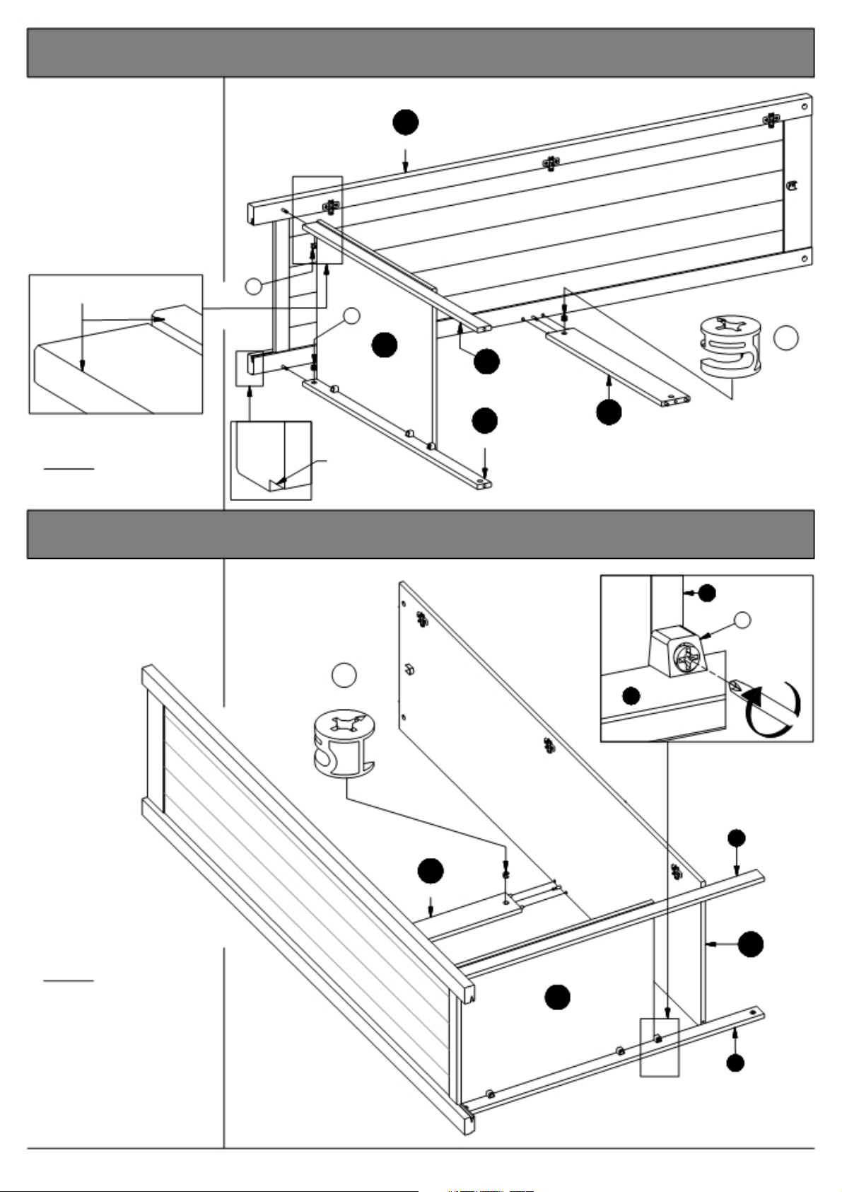
11. Adding the plinths and the rail to the left hand side.
Press the rail "8" and the
plinths "12" and "13" onto
the left hand side "1".
See page 4 "Function of the
cam & bolt".
Place the cams "A" into the
holes indicated, arrows
pointing towards the side /
bolt.
1
Side, left
Chamfer = Front
A
A
9
Bottom 13
Plinth, front
Fig. 11.1
Tighten:
Turn the cams to the right.
12
Plinth, back
Rabbet = Back
8
Rail
Fig. 11.2
12. Adding the divider to the plinths and the rail.
Press the divider "3"
onto the bottom "9" and
the rail "8".
See page 4 "Function of
the cam
& bolt".
A
1 Pcs.
Fig. 12.1
12
A
3 Pcs.
3
R
Place the cams "A" into
the holes indicated,
arrows pointing towards
the bolt.
Tighten:
Turn the cams to the
right.
Finally fix the divider "3"
onto the plinths "12" and
"13" using the mini
blocks "R".
See fig. 12.1
8
Rail
9
Bottom
Page 11 of 26
13
3
Divider
12
2½ door robe w. 3 drws.
Page 12
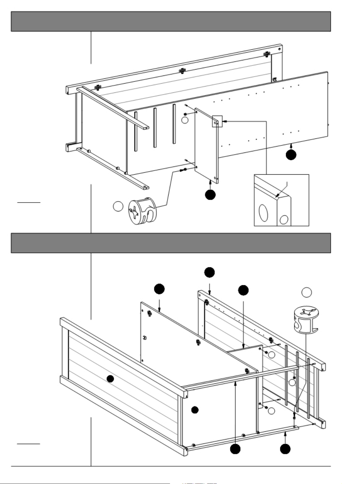
13. Adding the small bottom to the divider.
Press the small bottom
"10" onto the divider "3".
See page 4 "Function of
the cam & bolt".
A
Place the cams "A" into
the holes indicated,
arrows pointing towards
the bolt.
Tighten:
Turn the cams to the
right.
A
2 Pcs.
10
Bottom, small
Fig. 13.1
3
Divider
Chamfer = Front
14. Adding the side, right to the carcass.
Press the side, right "2"
onto the plinths "12" and
"13" and the small
bottom "10".
See page 4 "Function of
the cam & bolt".
Place the cams "A"
into the holes indicated,
arrows pointing towards
the side / bolt.
3
Divider
1
2
Side, right
9 A
10
A
Bottom, small 4 Pcs.
A
A
Tighten:
Turn the cams to the
right.
13 12
Plinth, front Plinth, back
Page 12 of 26
2½ door robe w. 3 drws.
Page 13
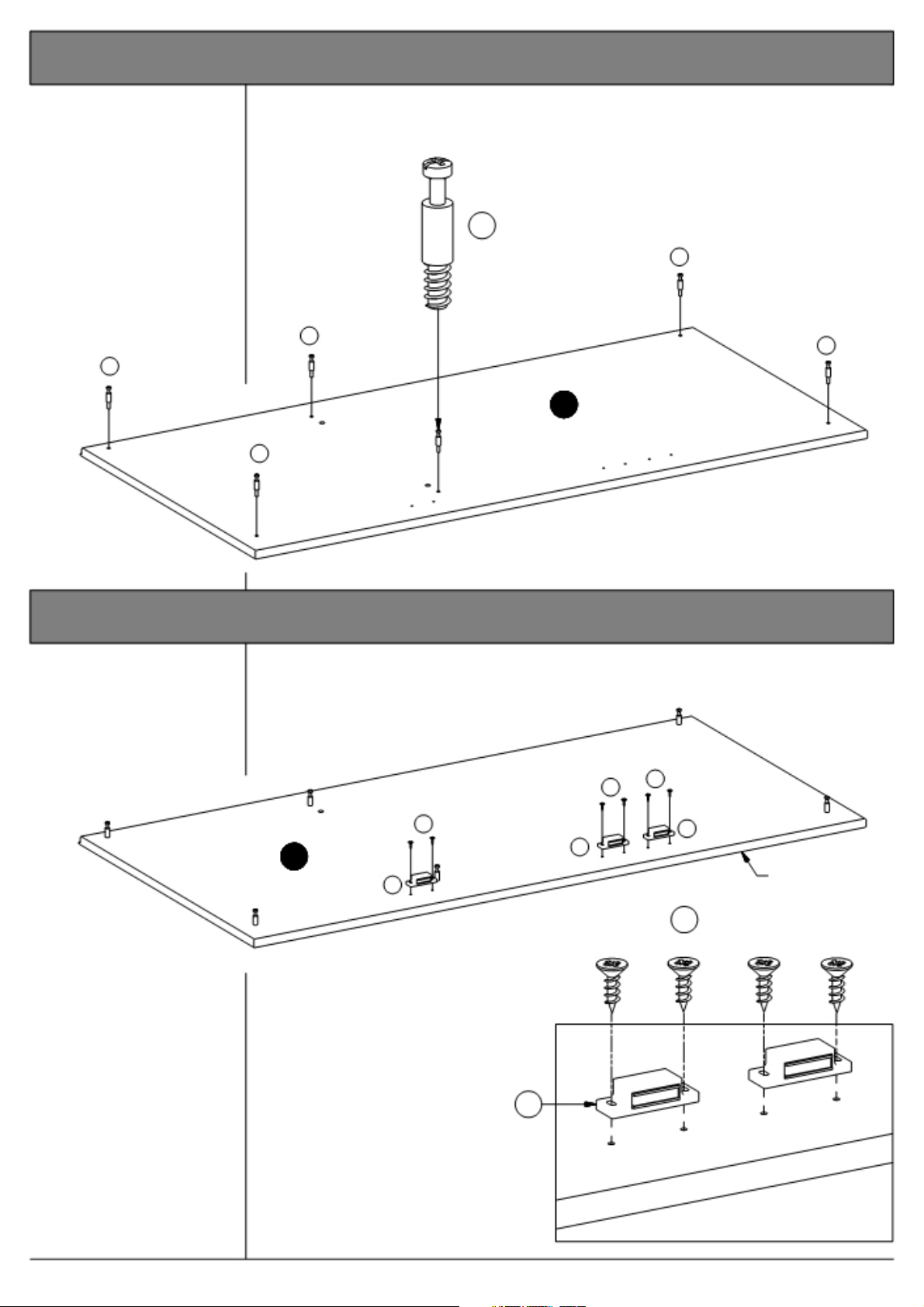
15. Mounting the bolts to the top.
Screw the bolts "C" into
the holes indicated on the
top "7".
C
6 Pcs.
C
C
C
7
Top
C
16. Mounting the magnets to the top.
Fix the magnets "H" to
the top "7" using
screws "D" into the
pre-drilled holes.
C
D
D
It is important that the
magnetic part points
towards the front edge
of the top.
See fig. 16.1
7
Top
D
H
H
H
Front edge
D
6 Pcs.
H
3 Pcs.
Fig. 16.1
Page 13 of 26
2½ door robe w. 3 drws.
Page 14
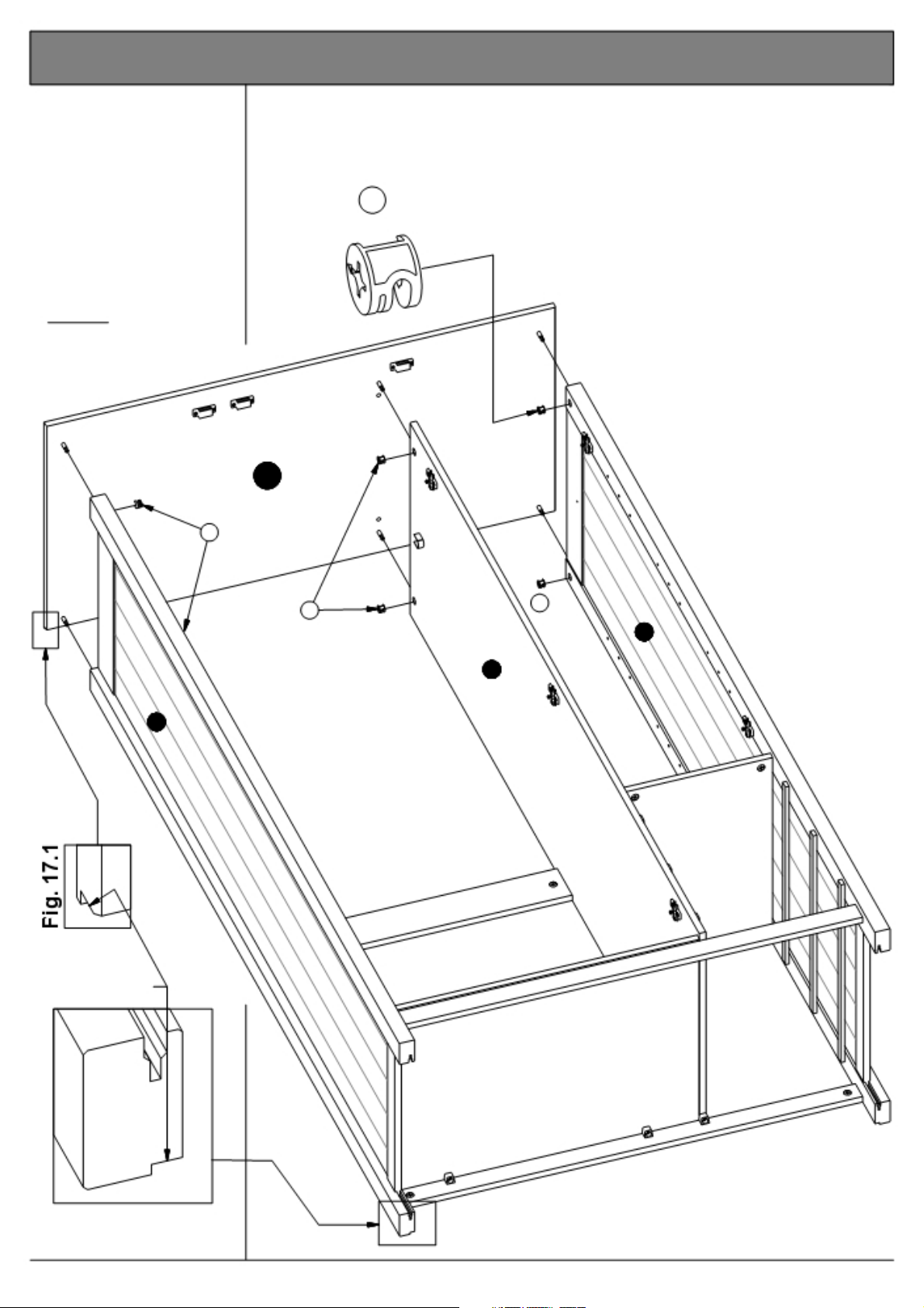
17. Assembling the top to the sides.
Lower the top "7" onto
the sides "1" and "2" and
the divider "3".
See page 4 "Function of
the cam & bolt".
Place the cams "A" into
the holes indicated,
arrows pointing towards
the top / bolt.
Tighten:
Turn the Cams to the
right.
7
Top
A
6 Pcs.
A
A
1
A
2
3
Rabbet = Back
Fig. 17.2
Page 14 of 26
2½ door robe w. 3 drws.
Page 15
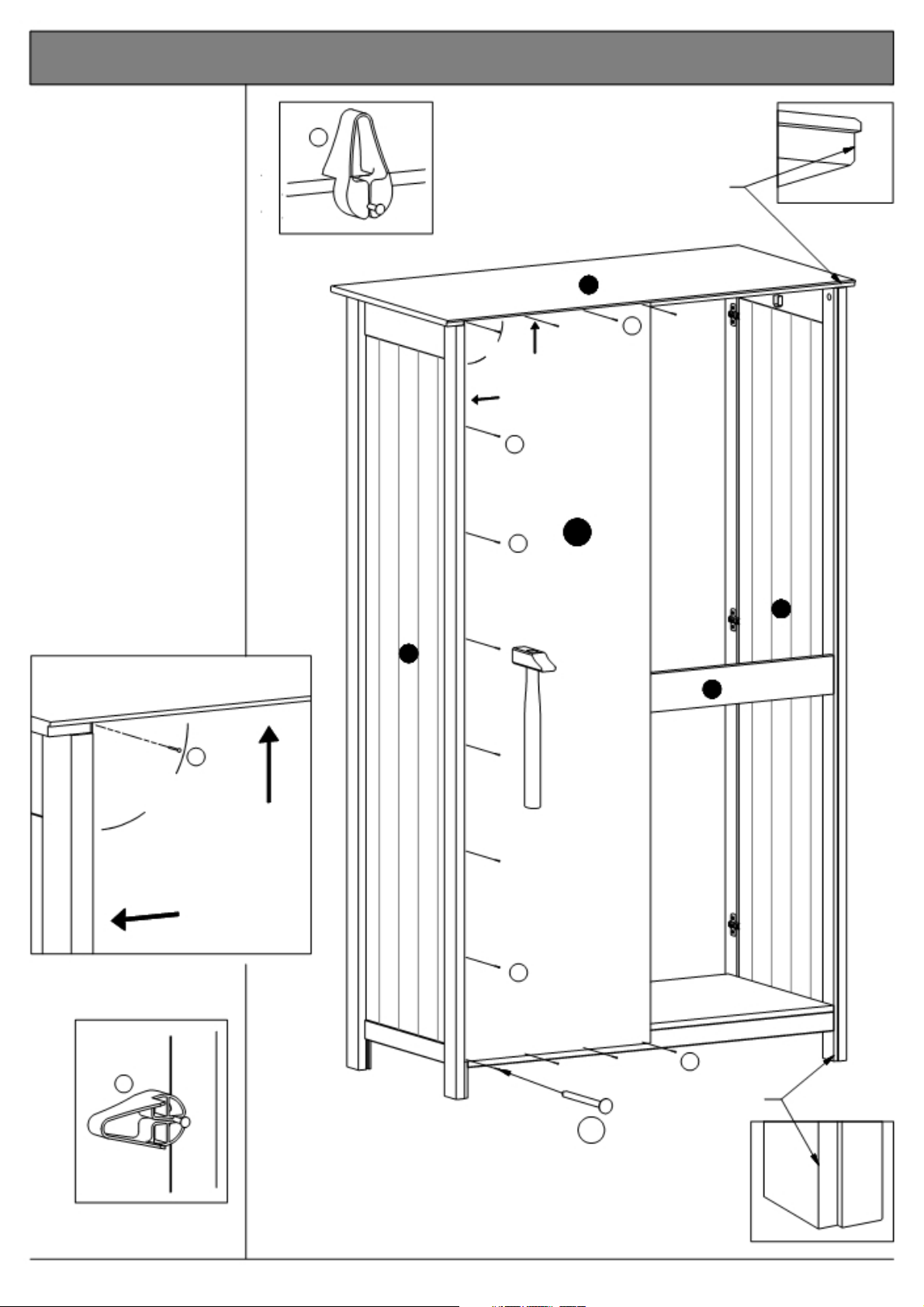
18. Adding the back to the carcass.
Place the back "17" into
the rabbet of the top "6"
and the side "2".
Ensure there is NO GAP
between the side and the
back, NOR between the
top and the back.
Fasten the back with
nails "G" along the top.
Use the nail guide "M" see fig. 16.4
The angle between the
top and the side must be
90 degrees. Fig. 16.2
To accomplish this,
ensure there is NO GAP
between the side and the
back.
Fasten the back along
the side and the bottom.
Use the nail guide as
shown in Fig. 16.5.
Fig. 16.4
M
Rabbet = Back
6
G
G
G
17
Back
Fig. 16.1
Fig. 16.2
1
2
8
G
90
G
M
Fig. 16.5
G
Rabbet = Back
G
14 Pcs.
Fig. 16.3
Page 15 of 26
2½ door robe w. 3 drws.
Page 16
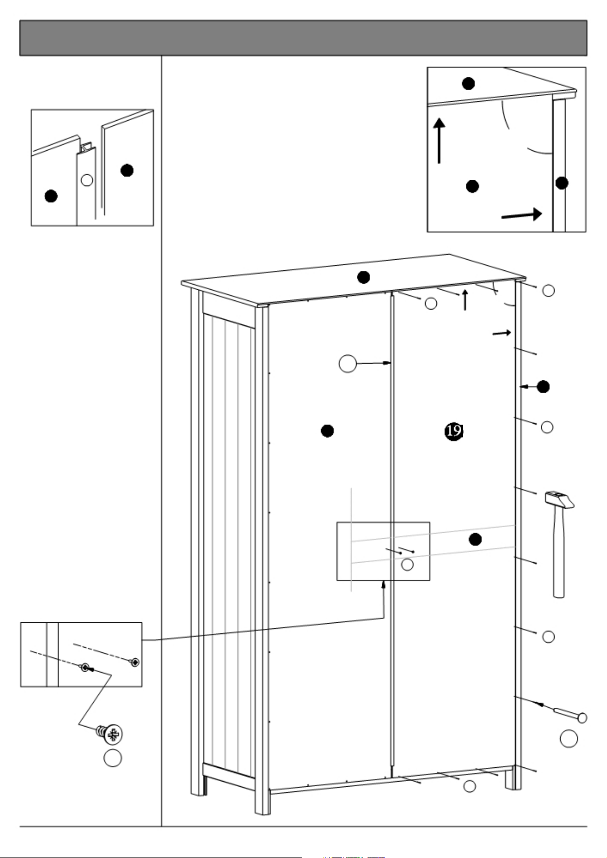
19. Adding the back and the joining strip to the carcass.
Place the joining strip
"S" onto the back.
See fig. 19.1
19
S
19
Fig. 19.1
Place the back into the
rabbet of the top "7" and
the side "1".
Ensure there is NO GAP
between the side and the
back, NOR between the
top and the back.
Fasten the back along
the top. Use the nail
guide - see page 14, fig.
18.4.
Ensure there is NO GAP
between the side and the
back.
7
S
Joining strip
19
fig. 19.2
G
Back
7
19
90
a
1
G
1
G
Fasten the back along
the side and the bottom.
Use the nail guide - see
page 14, fig. 18.5
Fix the back onto the
support rail "8" using
screws "D".
See fig. 19.3
Fig. 19.3
D
2 Pcs.
8
D
G
G
14 Pcs.
G
Page 16 of 26
2½ door robe w. 3 drws.
Page 17
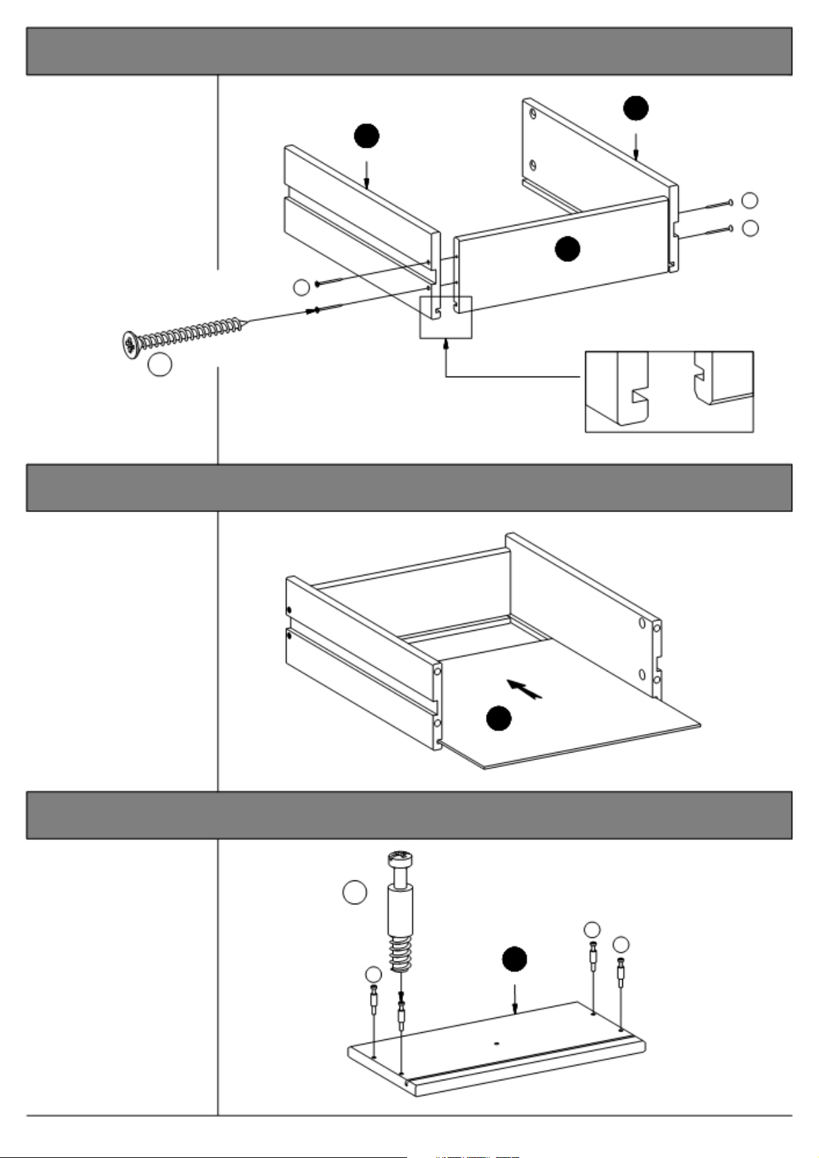
20. Mounting the drawer sides to the drawer back.
Fix the drawer sides
"15" and "16" to the
drawer back "17"
using screws "F".
The grooves of the
drawer sides and back
should be turned F
exactly as shown.
See fig. 20.1
F
16
3 Pcs.
17
3 Pcs.
F
12 Pcs.
15
3 Pcs.
Fig. 20.1
F
21. Sliding the drawer bottom into the drawer frame.
Slide the drawer bottom
"18" into the grooves of
the the drawer frame.
18
3 Pcs.
22. Mounting the bolts to the drawer front.
Screw the bolts "C"
into the holes
indicated on the
drawer front "14".
C
12 Pcs.
C
C
14
C 3 Pcs.
Page 17 of 26
2½ door robe w. 3 drws.
Page 18
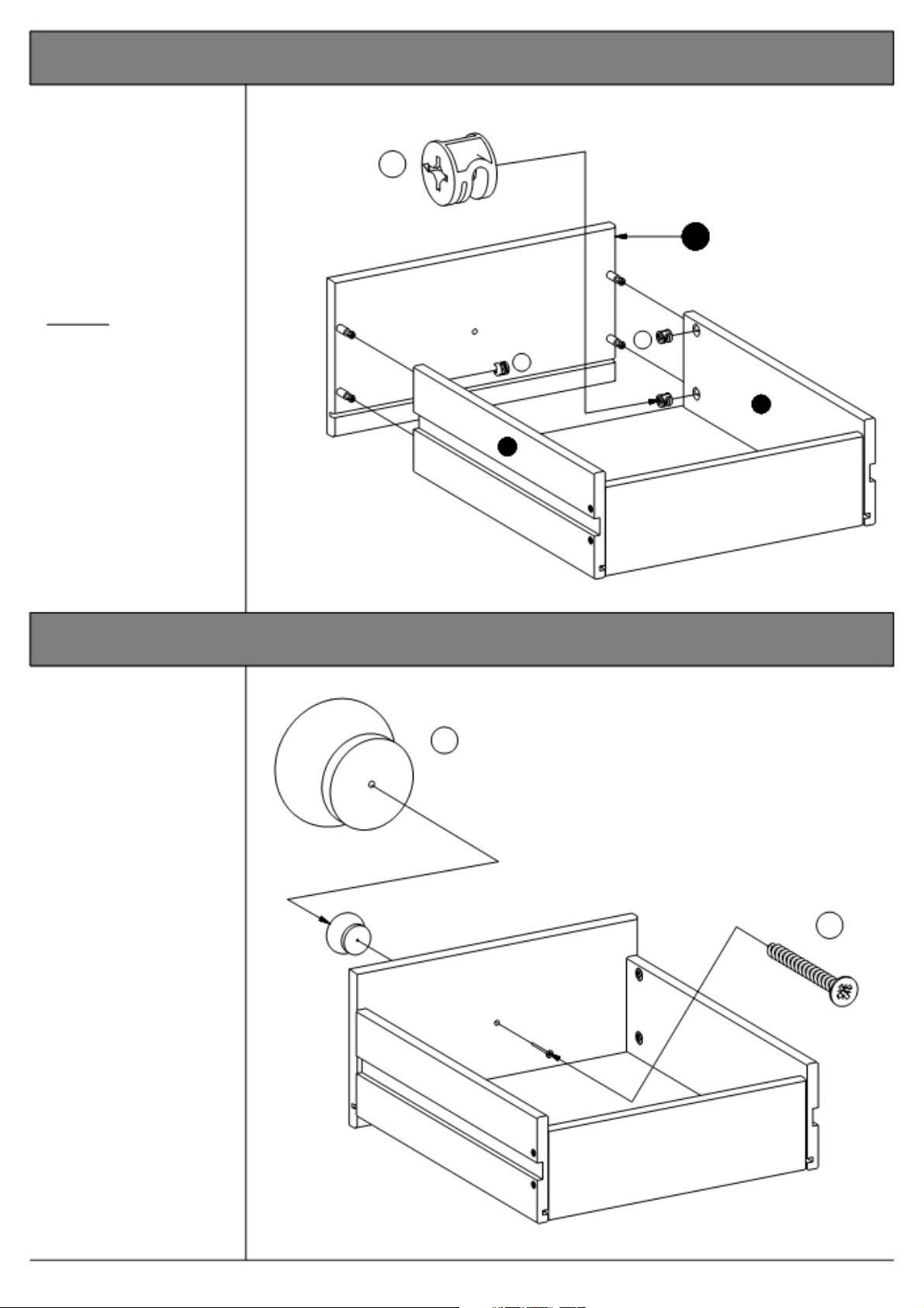
23. Adding the drawer front to the drawer frame.
Press the drawer front
"14" onto the drawer
sides "15" and "16".
See page 4 "Function of
cam & bolt".
B
12 Pcs.
Place the cams "B" into
the holes indicated,
arrows pointing towards
the drawer front / bolts.
Tighten:
Turn the cam to the
right.
B
16
B
24. Mounting the knobs to the drawer front.
14 Drawer front
3 Pcs.
15
Fix the knobs "K" to the
drawer front using
screws "F".
K
3 Pcs.
F
3 Pcs.
Page 18 of 26
2½ door robe w. 3 drws.
Page 19
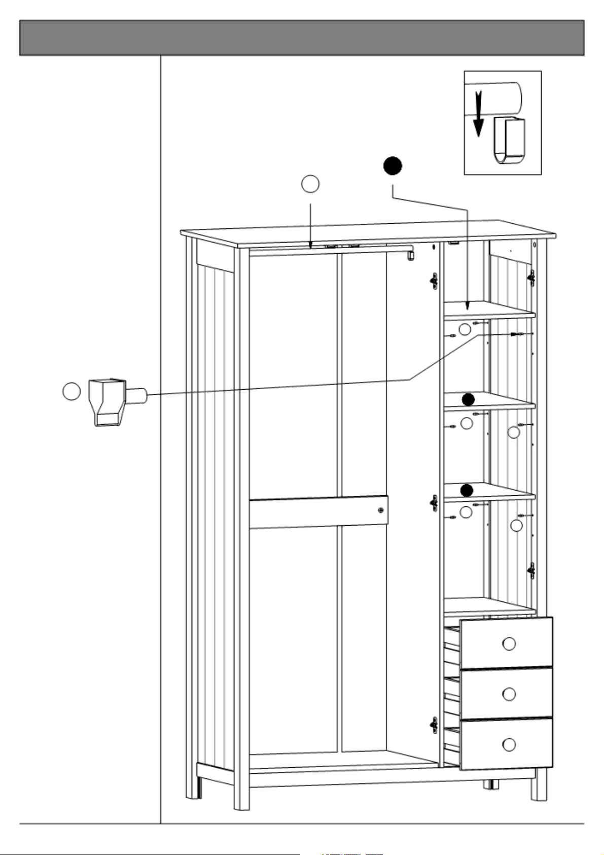
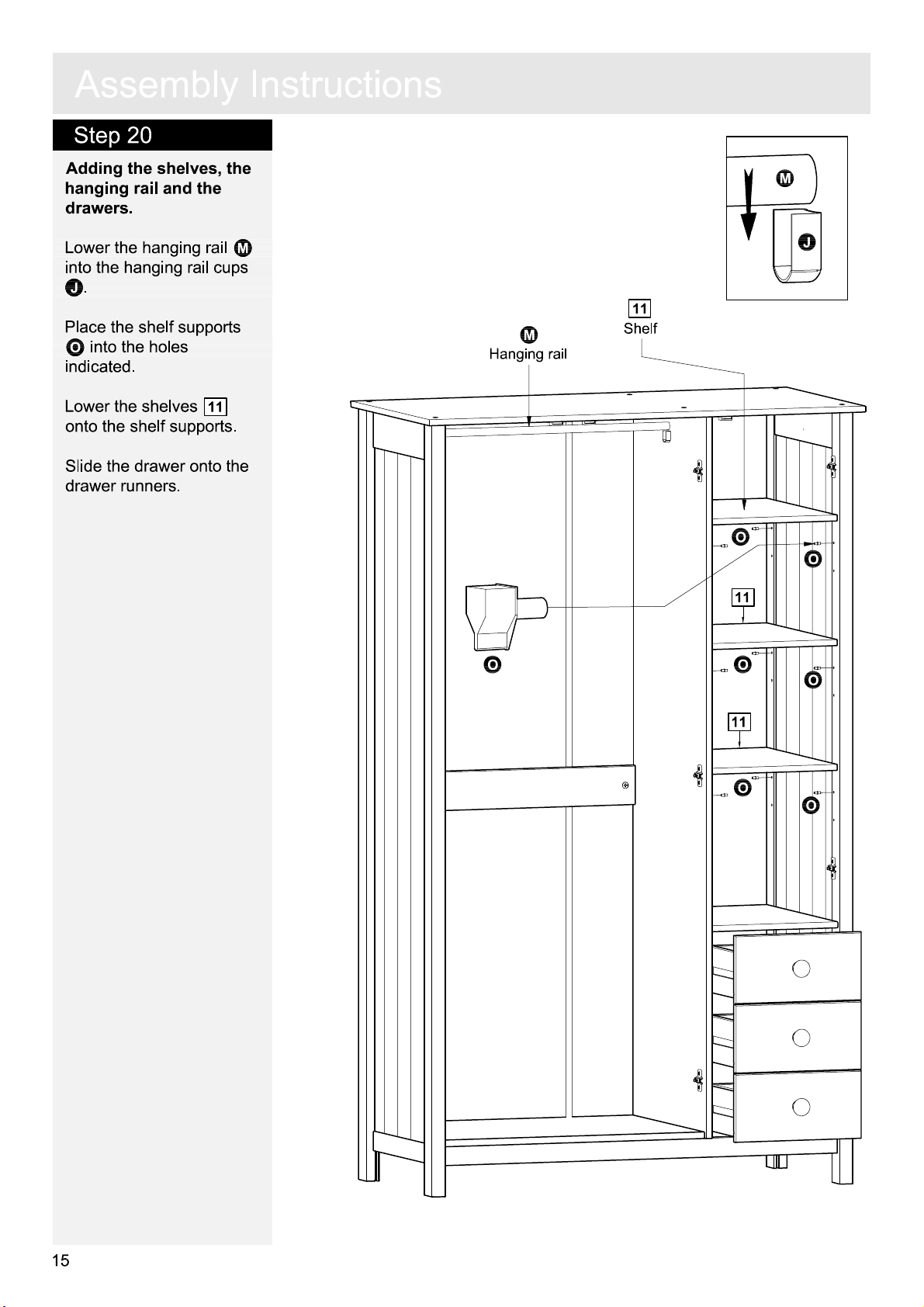
25. Adding the shelves, the hanging rail and the drawers.
Lower the hanging rail
"O" into the hanging rail
cups "L".
Place the shelf supports
"Q" into the holes
indicated.
Lower the shelves "11"
onto the shelf supports.
O
Hanging rail
11
3 Pcs.
Fig. 25.1
Shelf
Q
Q
12 Pcs.
Slide the drawers onto
the drawer runners.
11
Q
Q
11
Q
Q
Page 19 of 26
2½ door robe w. 3 drws.
Page 20
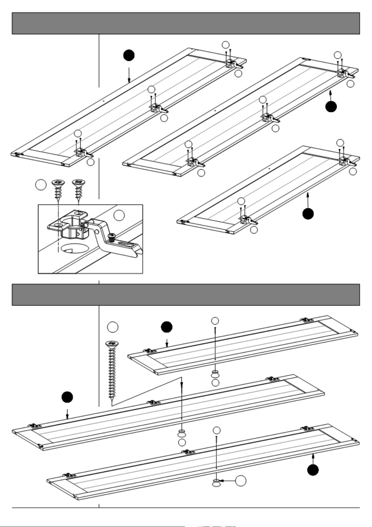
26. Mounting the cup hinges to the doors.
Lower the cup hinges
"N" into the holes
indicated on the doors
"4", "5" and "6".
Fix the hinges using
screws "D".
Fig. 26.1
D
D
16 Pcs.
D
6
Door, right
N
D
D
D
N
5
N
N
D
N
N
D
N
8 Pcs.
N
Door, small
Door, left
D
N
4
Fig. 26.1
27. Mounting the knobs to the doors.
Fasten the knobs "K" to
the doors "4", "5" and 6
using screws "F".
5
Door, left
F 4
3 Pcs.
Door, small
K
F
K
F
K
3 Pcs.
Page 20 of 26
Door, right
6
2½ door robe w. 3 drws.
Page 21
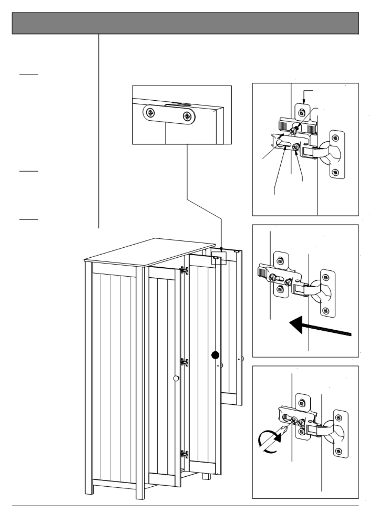
28. Mounting the doors to the carcass.
When placing the doors,
the magnet catches
MUST point upwards.
Step 1
Place the adjustment
hole of the cup hinge at
the level of the fixing
screw. Push the cup
hinge towards the cross
plate - placing the fixing
screw in the wider part
of the adjustment hole.
It is very IMPORTANT to
catch ALL of the fixing
screws.
Step 2
Push the door / cup
hinge inwards - placing
the fixing screw in the
narrow end of the
adjustment hole.
Step 3
Tighten the fixing
screws of ALL the cross
plates.
Fig. 28.1
Fig. 28.2
1
Adjustment
hole
2
Cross plate
Fixing screw
Adjusting
screw
6
3
Page 21 of 26
2½ door robe w. 3 drws.
Page 22
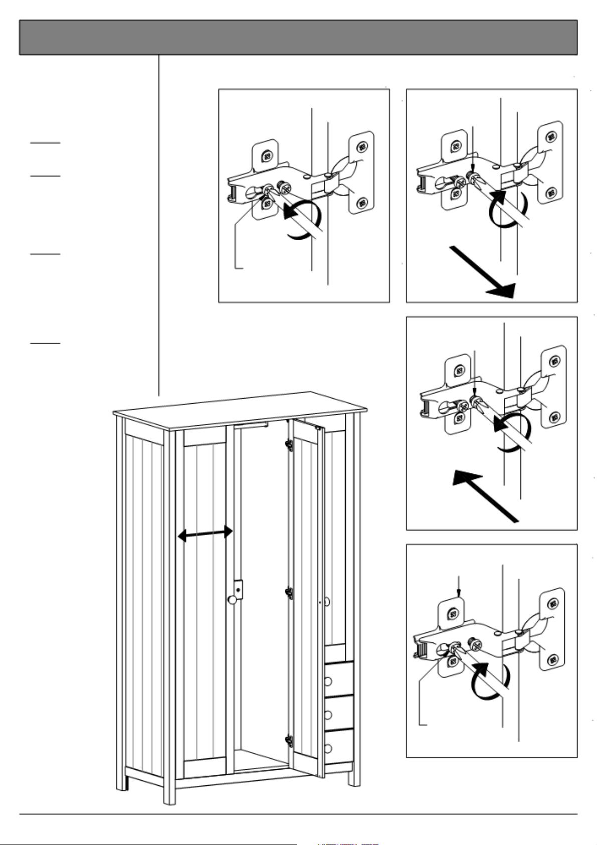
29a. Adjusting the doors from side to side.
MAKE SURE THE
WARDROBE IS PLACED
ON A PLANE SURFACE
BEFORE YOU BEGIN
ADJUSTING THE HINGES.
Step 1
Loosen the fixing screw.
Step 2
To adjust the door away
from the side (towards the
other door / the centre) turn the adjusting screw
to the right.
Step 3
To adjust the door
towards the side (away
from the other door / the
centre) - turn the
adjusting screw to the
left.
Step 4
Either continue
adjustment on page 22 step 2 - or tighten the
fixing screws of ALL the
cross plates.
Fig. 29a.1
1 2
Adjusting
screw
Fixing screw
3 Adjusting
screw
4
Cross plate
Fixing screw
Page 22 of 26
2½ door robe w. 3 drws.
Page 23
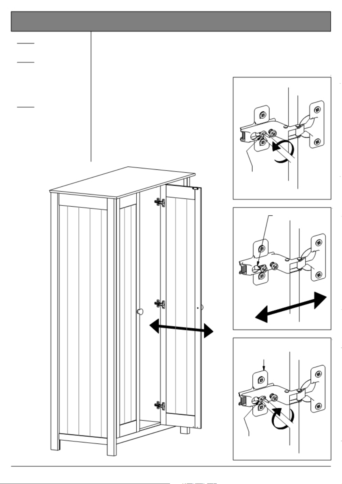
29b. Adjusting the doors forwards or backwards.
Step 1
Loosen the fixing screw.
Step 2
Push the cup hinges / the
door back OR forth to
adjust. The doors should
level with the front edge
of the sides.
Step 3
Tighten the fixing screws
of ALL the cross plates.
Fig. 29b.1
1
Fixing
screw
2
3
Cross plate
Adjustment hole
Fixing
screw
Page 23 of 26
2½ door robe w. 3 drws.
Page 24
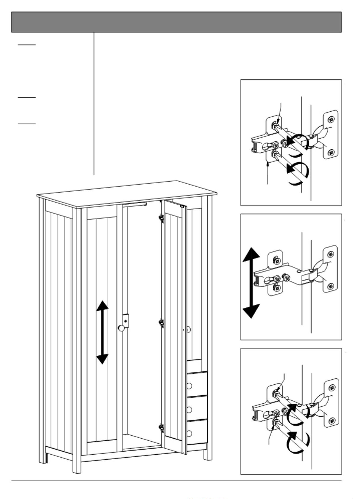
29c. Adjusting the doors up or down.
Step 1
Loosen the two screws
"E"/"D" of each cross
plate, BUT ONLY as
much as it will allow the
cross plate to move up
and down.
Step 2
Adjust the cross plate / "E"/"D"
the door.
Step 3
Tighten the screws
"E"/"D" of ALL the cross
plates.
Fig. 29c.1
1
Cross Plate
2
3
"E"/"D"
"E"/"D"
Page 24 of 26
2½ door robe w. 3 drws.
Page 25
Page 26

Dear Customer.
Please note that the product you have purchased is a
natural living timber.
Just like nature itself, wood varies in shape and colour.
Knots, vein patterns, resin pockets and colour differences
contribute to giving the piece of furniture its beauty and form a natural part of solid wood.
Although the tree has been cut down and dried, it is still
alive and therefore will react to high and low
temperatures, light, humidity, drought and time.
In cold and dry periods, the wood contracts which may
lead to small cracks in the piece of furniture. The reverse
happens in warm and humid periods where the wood
expands and this may result in slight unevenness.
The colour of the wood also changes with time,
particularly if the furniture is placed in a light place. This is a
natural process and part of owning a piece of
furniture made of solid wood.
Any flexing that has occurred during transport will
re-correct it self once this product is correctly assembled.
Tighten all joints of the furniture after six months.
Please keep these instructions in a safe place for future
use.
Page 26 of 26
2½ door robe w. 3 drws.
Page 27

Scandinavia - 3 Door Robe w
. 3 drws
.
A
ssembly Instructi
on
s
- Please k
eep for future reference
642/3784
643/8377
Dimension
Width - 107cm
Depth - 53c
Height -
Import
s
m
179.9cm
- Please r
an
t
ead these instructions
If you need help or have dam
fully before starting assembly
aged or missing parts, call the
Customer Helpline: 08456 400800
Issue 2 - 01/04/12
Page 28

!
Important
S
a
f
e
t
-
Please r
y
and
ead these instructions fully before starting assembl
C
a
r
e
A
d
v
i
c
e
y
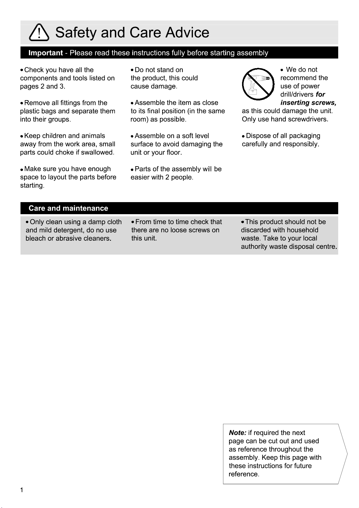
Check you have all t
com
ponents and tools listed
pages 2
Remove all fittings from t
plastic bags
into their gr
Keep children
away from the work area, small
parts could choke if swallowed
Make sure you have enough
space to layou
starting
Care
Only clean using a damp clot
and mild detergen
bleach or abrasive cl
and 3
.
and s
oups.
and animal
t the parts before
.
and maint
he
on
he
eparate the
s
enance
t, do no us
eaners
m
.
e
.
Do not stand on
the pr
oduct, this could
cause dam
Assemble the item as clos
to its final position (in the same
room) as possible.
Assemble on a soft leve
surface to avoid damaging the
un
it or your floor
Parts of the assembly will be
easier with 2
From time to time check tha
h
here are no loose screws
t
this uni
age
t.
.
.
people
.
l
e
on
t
We do no
use of powe
dr
inserting screws
as this could damage the unit.
Only use
Dispose of all packaging
carefully
This product should not be
discar
waste. Take to your loca
authority waste disposal centre
ded with
recomm
ill/drivers
hand screwdrivers
and res
ponsibly.
household
t
end the
r
for
l
,
.
.
Note:
page can be cut out and used
reference.
1
if r
equired the nex
as reference throughou
assembly. K
these instructions for future
eep this page wit
t
t t
he
h
Page 29

If you have damaged or missing components
C
o
m
ponen
t
s
-
P
ane
l
s
call the
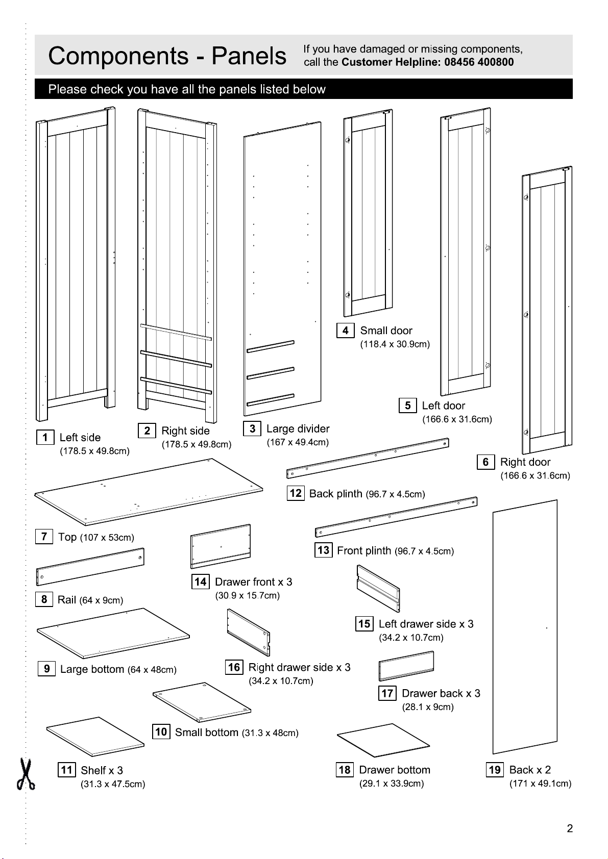
Please check you have all the panels listed below
Customer Helpline: 08456 400800
4
Small
doo
r
(
118.4 x 30.9cm
)
,
1
Left side
(
178.5 x 49.8cm
7
8
9
(
107 x 53cm
Top
Rail
(64 x 9cm)
Large bottom
2
Right side
(
)
)
(64 x 48cm)
178.5 x 49.8cm
)
14
Drawer front x
(30.9 x 15.7cm)
16
Divider
3
(
167 x 49.4cm
12
3
Right drawer side x
(34.2 x 10.7cm)
)
Back plinth
13
Front plinth
(96.7 x 4.5cm)
15
Left drawer side x 3
(34.2 x 10.7cm)
3
17
5
Left
doo
(
166.6 x 31.6cm
(96.7 x 4.5cm)
Drawer back x 3
(28.1 x 9cm)
r
)
6
Right doo
(
166.6 x 31.6cm
r
)
11
Shelf x 3
(31.3 x 47.5cm)
10
Small bottom
(31.3 x 48cm)
Drawer bottom x 3
18
(29.1 x 33.9cm)
Back x 2
19
(
171 x 49.1cm
)
2
Page 30

C
o
m
ponen
t
s
-
F
i
tt
i
ng
s
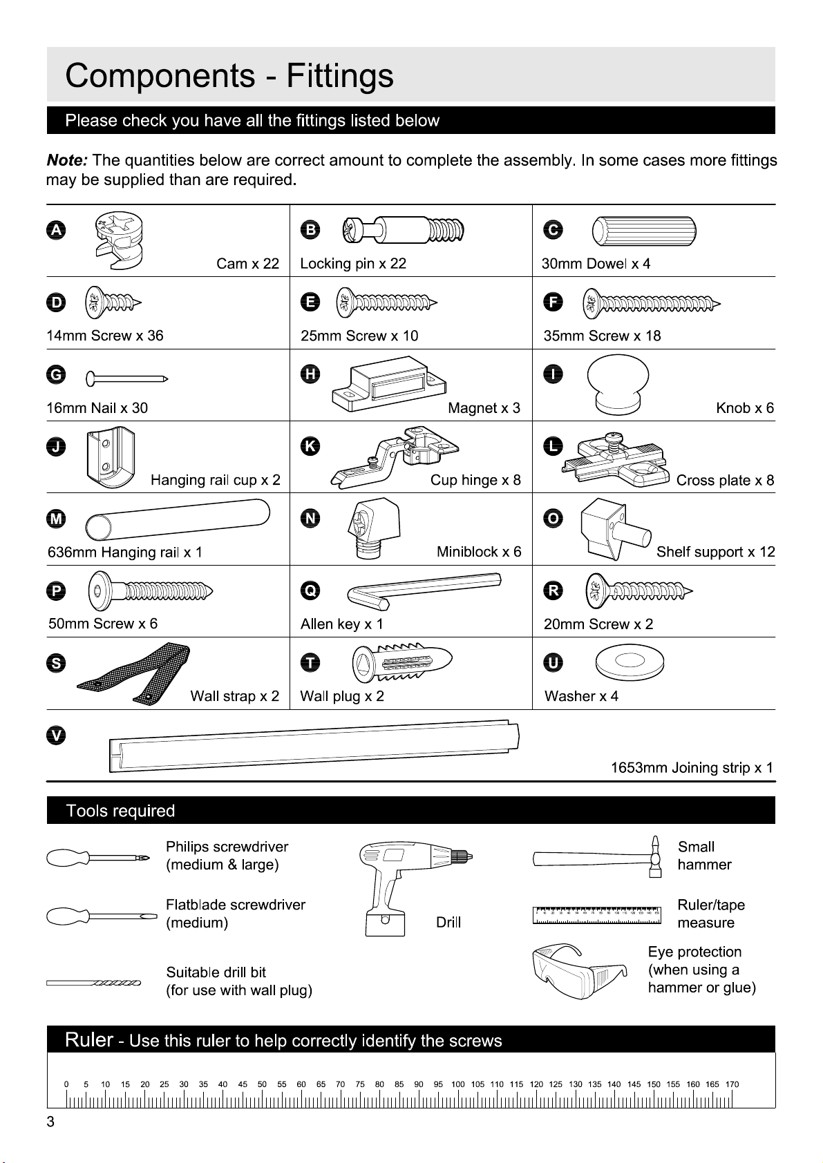
Please check you have all the fittings listed belo
Note:
The quantities below are correct am
may be s
A
D
14mm Screw x
G
16mm Nail x
J
upplied than are r
Large cam x 16
36
30
H
anging rail cup x
equired.
B
E
25mm Screw x
H
K
2
oun
t to complete the assembly
w
Small cam x
10
M
Cup hi
12
agnet x 3
nge x 8
. In some cases more fittings
C
Locking pin x
F
35mm Screw x
I
L
28
18
K
Cross plate x
nob x 6
8
M
636mm Hanging rail x 1
P
Wall strap x
S
Miniblock x
Tools requir
ed
Philips screwdrive
(medium & large
Flatblade screwdrive
(medium)
Suitable drill bit
(for use with wall plug
N
30mm Dowel x
Q
2
Wall plug x 2
T
6
r
)
r
)
4
Shelf support
Drill
x
O
20mm Screw x
R
Washer x 4
U
12
0
40
30
20
10
2
1653mm Joining strip x 1
Sma
hamme
70
50
60
8090100 110
120
150
130
140
Ruler/tape
measur
Eye protection
(when using
ha
mmer or glue)
ll
r
e
a
Ruler
0
3
- Use this ruler to help correctly identify the screws
55
35
30
5
10
25
15
20
50
45
40
65
60
75
70
9080
85 95
100
105
110
115 125
120
130
135
145 155 165
140
150
160
170
Page 31

C
o
m
ponen
U
t
s
-
K
7
e
y
D
19
i
ag
11
r
a
m
14
4
16
x 3
19
11
2
3
1
8
9
12
11
10
13
5
15
6
17
18
F
un
c
t
i
on
Step 1
:
Fix the locking pin to
the wooden panel.
1
C
o
f
C
a
m
and
Step 2
:
Push the wooden panel with
the attac
onto the other wooden panel.
hed locking pin
2
Lo
ck
i
ng
Step 3
:
Place the cam into t
hole, arrow pointing
towards the locking pin
3
P
A
i
n
he
Step 4
:
Tighten: Turn the cam to
t
he righ
t.
.
4
B
4
Page 32

A
ss
e
m
b
l
y
I
n
s
t
r
u
c
t
i
on
s
Step 1
M
ounting the cross
plates to the sides
Fix the cross plates
the sides
the screws
holes indicated.
It is important that the
cross plates are placed
exactly as shown
The short
cross plates must poin
towards the front edge of
the sides
1
&
E
end of the
.
.
L
2
using
into the
.
to
t
2
Side, righ
t
E
L
Fron
E
L
E
t
Side, lef
E
Long end
1
t
L
Short end
Fron
t
E
L
E
L
Fron
t
L
5
Page 33

A
ss
e
m
b
l
Step 2
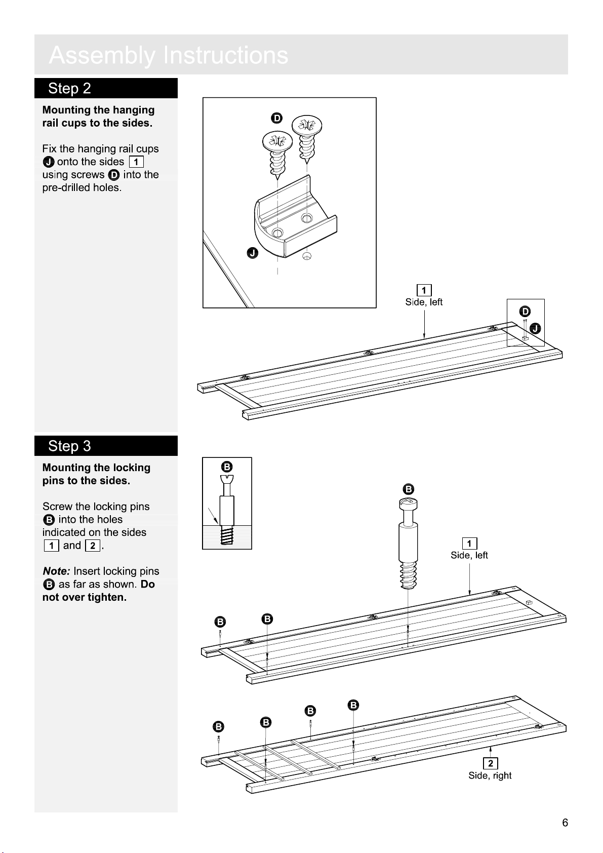
M
ounting the
rail cups to the sides.
hanging
y
I
n
s
t
r
u
c
t
i
on
s
D
Fix the hanging rail cups
J
onto the sides
2
and
using screws
into the pre-dr
1
D
illed holes
.
J
1
Side, lef
t
D
J
Step 3
M
ounting the locking
pins to the sides
Screw the locking pins
C
into the holes
indicated on the sides
1
and
Note:
Insert locking pin
C
as far as shown
not over tighten
.
2
.
.
Do
.
s
C
C
1
Side, lef
C
C
C
C
C
C
t
2
Side, righ
t
6
Page 34

A
ss
e
m
b
l
y
I
n
s
t
r
u
c
t
i
on
s
Step 4
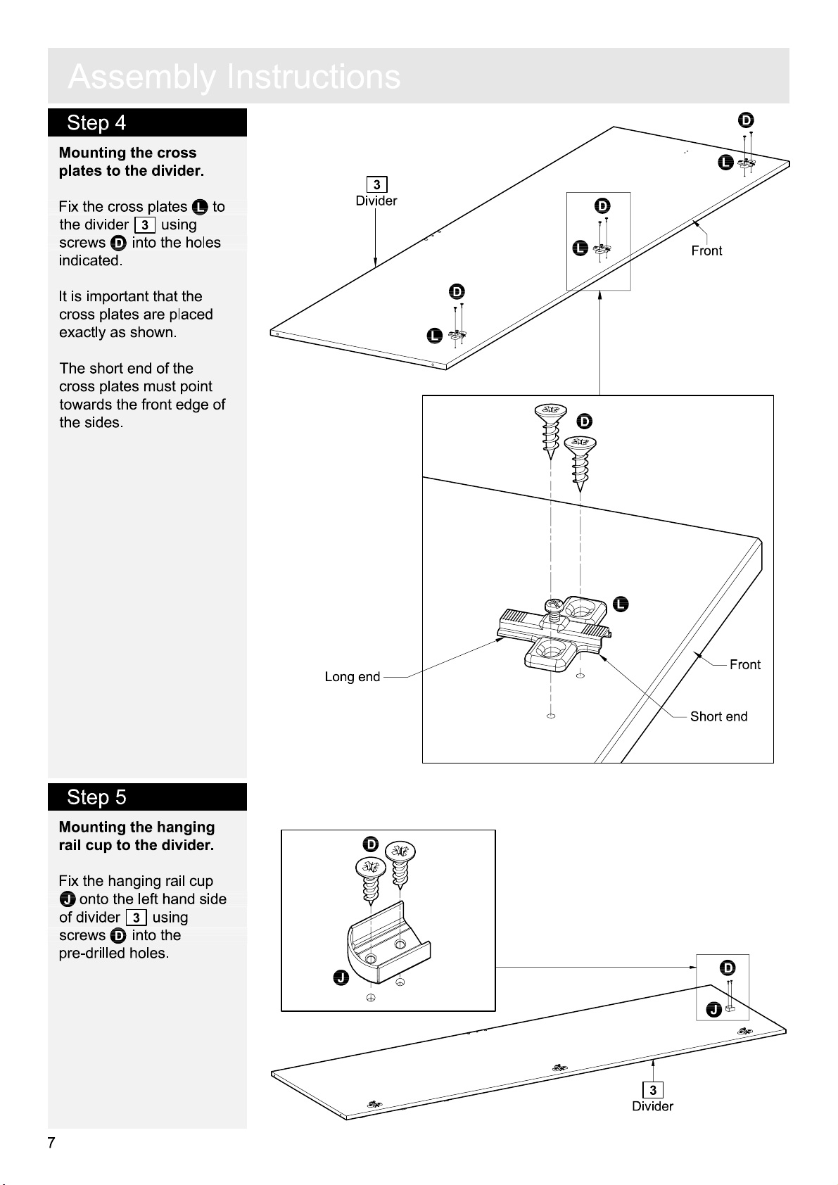
M
ounting the cross
plates to the divider
Fix the cross plates
the divider
screws
indicated
It is important that the
cross plates are placed
exactly as shown
The short
cross plates must poin
towards the front edge of
the sides
3
D
into the holes
.
end of the
.
.
using
.
L
to
t
3
Divide
D
L
r
D
L
D
L
D
Fron
t
Step 5
M
ounting the
rail cup to the divider
Fix the hanging rail cup
J
onto the left
of divider
screws
pre-drilled holes
hanging
3
using
D
into the
.
hand side
.
L
Fron
t
Long end
Short end
D
J
D
J
3
Divide
r
7
Page 35

A
ss
e
m
b
l
y
I
n
s
t
r
u
c
t
i
on
s
Step 6
M
ounting the locking
pin to the left hand side
of the divider
Screw the locking pin
into the hole indicated on
the left
divider
Note:
Insert locking pin
C
as far as shown
not over tighten
.
hand side of the
.
3
.
.
Do
C
Step 7
M
ounting the locking
pins to the right
side of the divider
hand
.
C
3
Divide
r
C
C
C
.
Do
C
s
Screw the locking pins
into the holes indicated on
the right
divider
Note:
C
as far as shown
not over tighten
hand side of the
.
3
Insert locking pin
.
Step 8
Adding the dowels to
the rail.
nsert the dowels
I
he holes indicated on
t
.
8
he rail
t
N
into
C
3
Divide
r
N
N
N
N
8
Rail
8
Page 36
A
ss
Step 9
e
m
b
l
y
I
n
s
t
r
u
c
t
i
on
s
Adding the miniblocks
to the plinths
Inser
t the miniblocks
into the holes indicated on
the plinths
12
.
and
13
S
.
S
S
Plinth, fron
S
13
12
Plinth, ba
t
S
ck
S
S
S
Step 10
M
ounting the plinths to
the bottom
Fix the plinths
to the bottom
screws in the miniblocks
.
S
The front plinth
be placed near the
chamfered edge of the
bottom.
.
12
9
13
and
using
mus
13
t
12
13
Plinth, fron
Plinth, ba
t
ck
9
Bottom, lar
ge
9
Page 37
A
ss
e
m
b
l
y
Step 11
Adding the plinths and
the rail to the left
side
.
Fit the rail
plinths
the left
See
page 4 "Function of
8
and the
12
and
hand side
cam and locking pin".
Place the large cams
into the holes indicated
arrows pointing towards
the side / locking pins
To tighten cams: Turn to
he right using a
t
screwdriver.
hand
13
onto
1
.
.
A
,
I
n
s
t
r
u
c
Chamfer = front
A
t
i
on
A
s
9
Bottom
13
Plinth, fron
t
8
Rail
1
Side, lef
t
A
Step 12
Adding the divider to
the plinths and the rail
Fit the divider
bottom
.
8
See
page 4 "Function of
9
and the rail
cam and locking pin".
Place the large cam
into the hole indicated,
arrow pointing toward the
divider / locking pin.
To tighten cams: Turn to
he right using a
t
screwdriver.
Finally fix the divider
onto the plinths
13
using the miniblo
.
S
.
3
onto the
A
3
12
and
cks
R
abbet = Back
A
8
Rail
12
Plinth, ba
ck
Bottom
3
12
9
S
13
3
Divide
12
r
10
Page 38
A
ss
e
m
b
l
y
I
Step 13
Adding the small bottom
to the divider
Fit the small bottom
onto the divider
See
page 4 "Function of
cam and locking pin".
Place the large cams
into the holes indicated
arrows pointing towards
the divider
.
10
.
3
A
,
/ locking pins
.
n
s
t
r
u
c
t
i
on
s
A
3
Divide
r
To tighten cams: Turn to
he right using a
t
screwdriver.
Step 14
Step 14
Adding the right
side to the small bottom
hand
and the plinths.
Fit the right
onto the plinths
13
and the small bottom
.
10
hand side
12
and
10
Bottom, sma
A
2
3
Divide
r
2
Side, righ
ll
t
10
Bottom, sma
Chamfer = front
A
ll
See
page 4 "Function of
cam and locking pin".
Place the large cams
into the holes indicated
arrows pointing towards
the side / locking pins
To tighten cams: Turn to
he right using a
t
screwdriver.
11
.
A
,
1
Side, lef
t
13
Plinth, fron
t
A
A
A
12
Plinth, ba
ck
Page 39

A
ss
e
m
b
l
y
I
n
s
t
r
u
c
t
i
on
s
Step 15
M
ounting the locking
pins to the top.
Screw the locking pins
C
into the holes
7
indicated on the top
Note:
Insert locking pin
C
as far as shown
not over tighten
.
.
Do
.
Step 16
s
C
C
C
C
C
7
T
C
op
C
M
ounting the magnets
to the top.
Fix the m
the top
D
into the pre-drilled
holes.
It is important that t
m
agnetic part points
towards the front edge of
the top.
agnets
7
using screws
H
to
he
T
7
op
D
D
D
H
H
D
H
H
Front edge
Front edge
12
Page 40
A
ss
e
Step 17
m
b
l
y
I
n
s
t
r
u
c
t
i
on
s
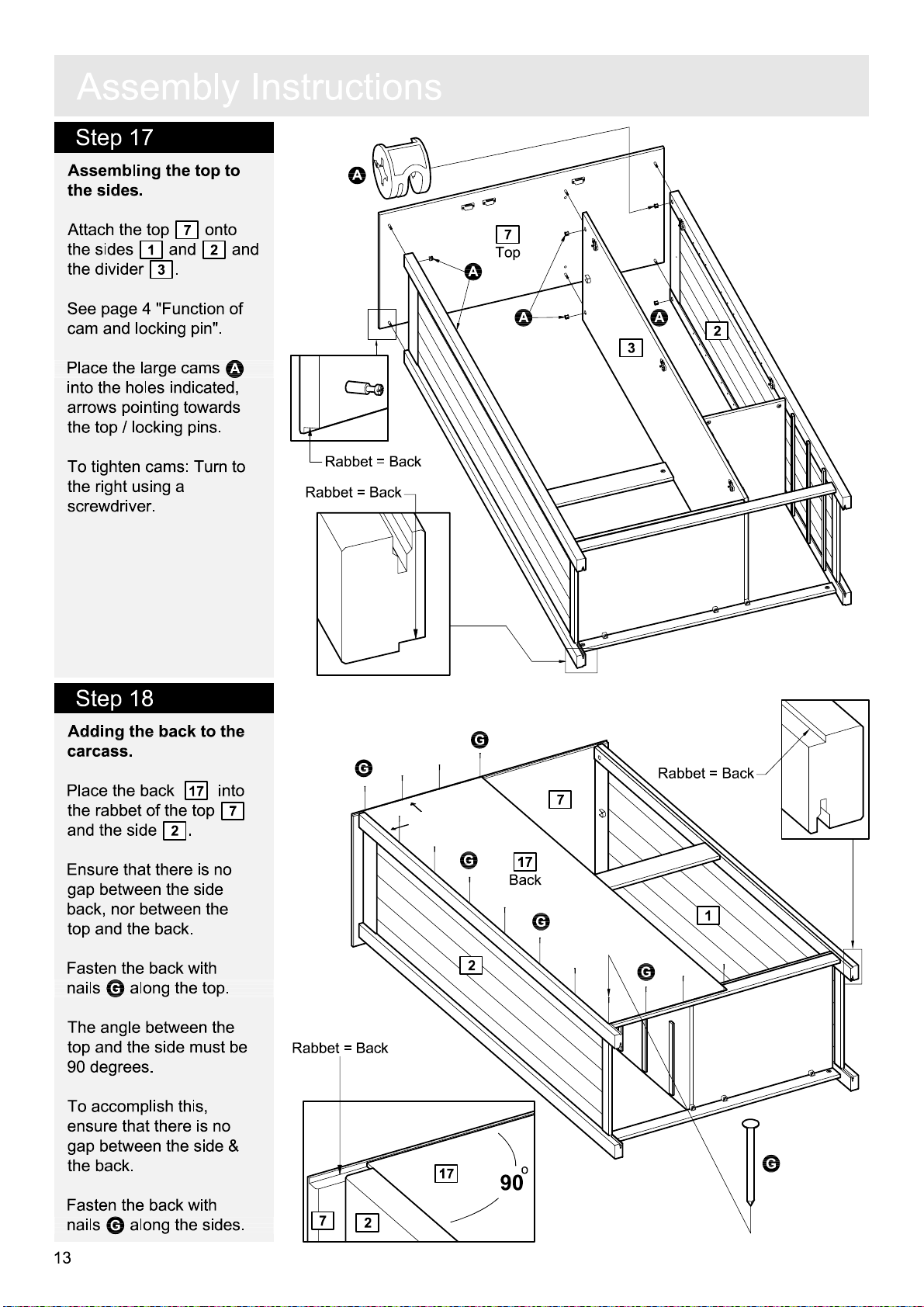
Assembling the top to
the sides
Attach the top
the sides
he divider
t
See
.
1
and
.
3
page 4 "Function of
7
onto
2
and
cam and locking pin".
A
Place the large cams
into the holes indicated
,
arrows pointing towards
the top / locking pins
.
To tighten cams: Turn to
he right using a
t
screwdriver.
A
7
R
abbet = Back
R
abbet = Back
T
op
A
A A
3
2
Step 18
Adding the back to the
carcass.
Place the back
the rabbet of the top
and the side
Ensure that there is no
gap betw
back, nor betw
top
Fasten the back with
nails
The
top
een the side
and the back.
G
al
angle betw
and the side must be
90 degrees.
To accomplish this
ensure tha
gap betw
the back
Fasten the back with
nails
een the side &
.
G
al
17
into
2
.
een the
ong the top
een the
,
t there is no
ong the sides.
.
G
7
G
R
abbet = Back
7
G
2
17
Back
G
G
1
R
abbet = Back
17
7
2
o
90
G
13
Page 41

A
ss
e
m
b
l
y
Step 19
Adding the back & the
joining strip to the
carcass.
Place the joining strip
onto the back.
I
U
n
s
t
r
u
c
t
i
on
s
D
Place the back
the rabbet of the top
and the side
Ensure that there is no
gap betw
back, nor betw
top
Fasten the back with
nails
and bottom.
Fix the back onto the
s
upport rail
screws
een the side &
and the back.
G
al
D
.
17
into
1
.
een the
ong the side
8
using
7
17
Back
D
G
G
8
G
1
G
G
G
U
Joining stri
2
p
17
17
U
17
14
Page 42

A
ss
e
m
b
Step 20
Drawer assembly.
Fix the drawer sides
a
:
15
drawer back
screws
and
F
.
16
to the
17
using
l
y
I
n
s
t
a
F
r
u
:
c
t
i
on
s
16
15
17
F
F
F
Slide the drawer
b
:
bottom
18
into the
grooves of the drawer
frame
.
c
:
Screw the locking pins
C
into the holes indicated
14
16
.
Do
.
.
B
,
on the drawer front
Note:
Insert locking pin
C
as far as shown
not over tighten
Press the drawer front
d
:
14
onto the drawer
sides
Place the small cams
into the holes indicated
15
and
.
arrows pointing towards
the drawer fron
t / locking
pins.
To tighten cams: Turn to
t
he right using a
screwdriver.
"Function of cam
and
locking pin" see page 4
s
.
b
:
18
C
c
:
B
d
:
14
C
C
14
B
B
C
C
15
C
17
16
Fix the k
e
:
drawer front
screw
R
epeat with remaining
drawer.
15
nob
14
F
.
I
to the
using
e
:
I
14
F
Page 43

A
ss
e
Step 21
m
b
l
y
I
n
s
t
r
u
c
t
i
on
s
Adding the shelves
hanging rail and the
drawers to the carcass.
Lower the
into the
.
J
Place the shelf supports
T
into the holes
indicated
Lower the shelves
onto the shelf supports.
Slide the drawer onto the
drawer runners
hanging rail
hanging rail cups
.
.
, the
11
M
M
H
anging rail
11
Shel
M
J
f
T
T
11
T
T
T
11
T
T
16
Page 44

A
A
ss
e
ss
e
m
m
b
l
b
l
y
I
y
I
n
s
n
s
t
r
t
r
u
c
u
c
t
i
on
t
i
on
s
s
Step 22
M
ounting the cup
hinges to the
Fix the cup hi
he holes indicated on the
t
doors
Attach the hinges using
screws
4
and
.
6
D
.
doors
nges
5
.
K
into
and
6
Door, righ
D
K
5
Door, lef
t
D
K
D
K
t
D
D
K
K
D
K
D
4
K
Door, sma
D
D
K
ll
Step 23
M
ounting the knobs to
the
doors
.
Fasten the k
the
doors
6
and
nobs
4
and
using screws
I
to
5
K
F
F
.
4
Door, sma
ll
F
I
5
I
F
Door, lef
t
17
I
6
Door, righ
t
Page 45

A
ss
e
m
b
l
y
I
Step 24
M
ounting the
the carcass
W
hen placing the
he m
agnetic catch plates
t
must be a
doors
.
a
:
Place the adjustmen
hole of the cup hinge a
t
he level of the fixing
screw. Push the cup
hinge towards the cross
place - placing the fixing
screw in the wider part of
the adjustment hole.
Important:
!
all three of the
fixing screws.
b
:
Push the
hinge inwards - placing
the fixing screw in the
narrow
adjustment hole
doors to
.
t the top of the
Ensure you catch
door / cup
end of the
doors
.
,
t
t
n
s
t
r
u
c
t
i
on
s
a
:
Cro
ss
plat
Adjustment
hol
b
:
e
e
Fixing scre
Adjusti
screw
w
ng
c
:
Tighten the fixing
screws of all three of the
cross plates
.
c
:
18
Page 46

A
ss
e
m
b
l
y
I
n
s
t
r
u
c
t
i
on
s
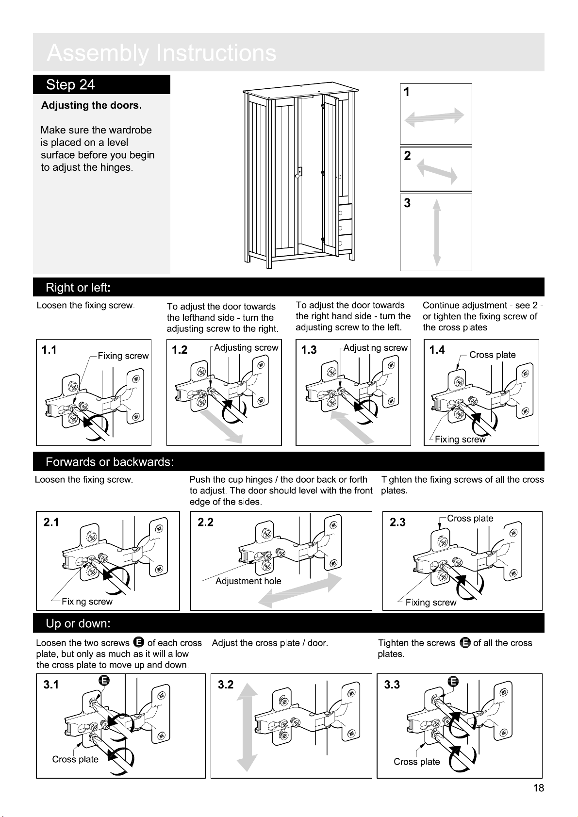
Step 25
Adjusting the
Make sure the wardr
is placed on a level
surface before you
to adjus
Right or left:
Loosen the fixing screw.
1.1
doors
t the hi
Fixing scre
.
begin
nges.
obe
w
To adjus
the left
adjusting screw to the right.
1.2
t the
door towards
hand side - turn the
Adjusting screw
To adjus
t
he right hand side - turn the
adjusting screw to the left.
1.3
t the
door towards
Adjusting screw
1
2
3
Continue adjustment - see 2
or tighten the fixing screw of
the cross plate
1.4
s
Cross plat
-
e
Forwards or backwards
Loosen the fixing screw.
Fixing scre
Up or down
Loosen the two screws of each cro
plate, but only as much as it will allow
the cross plate to move up
w
:
E
E
:
and down
.
Push the cup hinges / the
to adjus
edge of the sides
t. The door should level with the front
.
2.22.1
Adjustment hol
ss
Adjus
t the cross plate
e
door back or fort
/
door.
Fixing scre
Tighten the fixing screws of all the cro
h
plates.
2.3
Fixing scre
Tighten the screws
plates.
3.33.23.1
Cross plat
w
E
w
e
E
of all the cross
ss
19
Cross plat
e
Cross plat
e
Page 47

A
ss
e
m
b
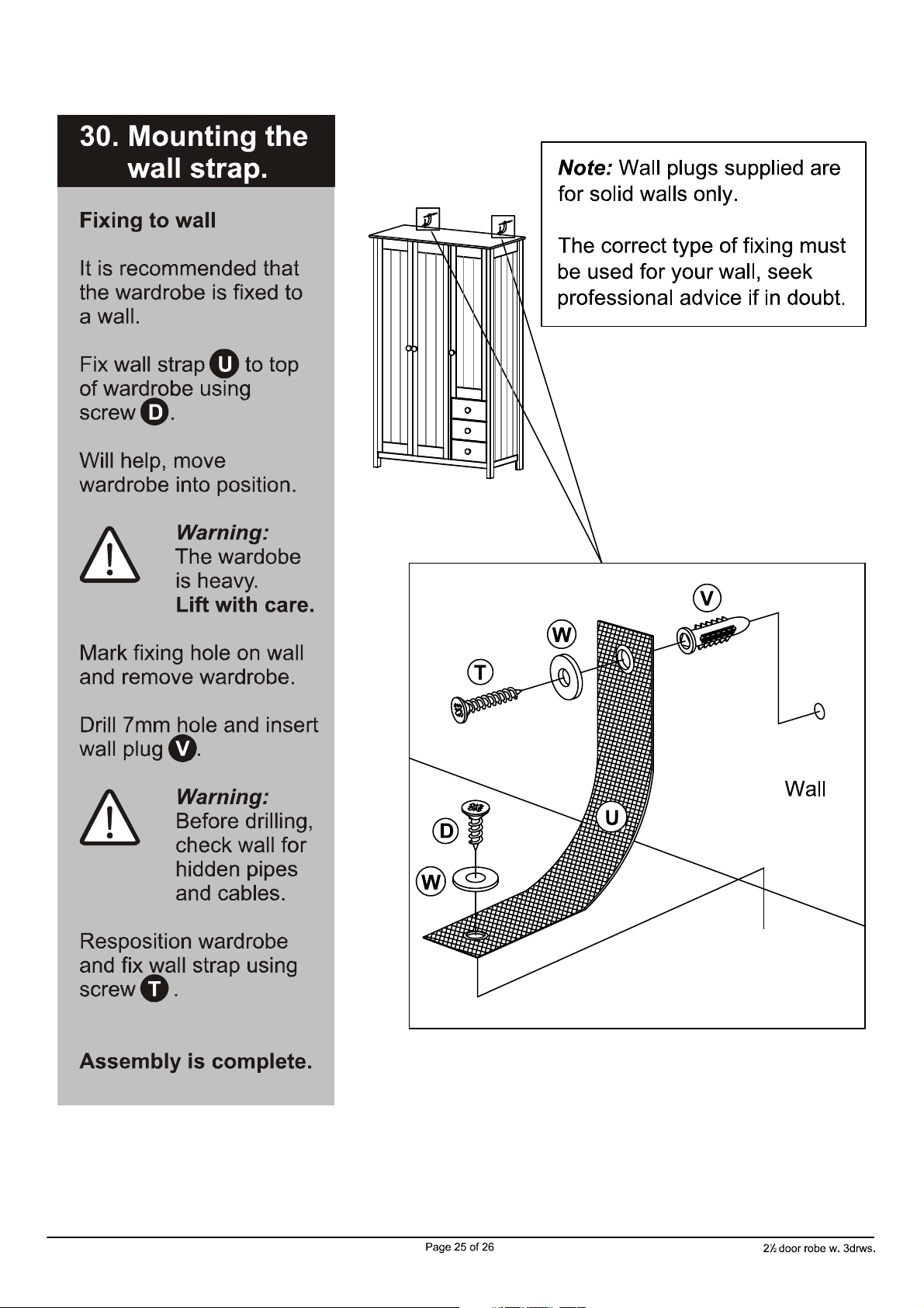
Step 26
Fixing to wall
It is recomm
the wardrobe is fixed
to a wall.
Fix wall straps
of wardrobe usi
screws
D
.
.
ended tha
P
to t
ng
l
y
t
op
I
n
s
t
r
u
c
t
i
on
s
Note:
Wall plugs s
for solid walls only
The correct type of fixing must
be used for your wall, seek
professi
onal advice if in
upplied are
.
doub
t.
With help, move
wardr
obe into position
The wardr
!
!
is heavy.
Mark fixing holes on wall
and remove wardrobe
Drill 7mm holes and inser
wall plugs
Before drilling,
!
!
check wall fo
hi
R
eposition wardrobe
and fix wall straps usi
.
screws
O
Warning:
obe
Lift with care
.
Q
Warning:
dden pipe
and cables
.
.
.
.
r
s
ng
t
Q
R
O
Assembly is complete
If you need help or have dam
.
D
R
aged or missing parts, call the
P
Customer Helpline: 08456 400800
Wall
20
Page 48

A Guide to - Wall Mounting & Fixings
Important note:
If plastic wall plugs
are supplied with
product:
your
- these are only suitable for
use in masonry walls.
If you are in any doubt about
the correct wall plugs for
your wall, seek professional
advice.
Failure of the product due to
using incorrect fixings is the
responsibility of the installer.
Types of walls
No.1
“General Purpose” wall plug
Generally aerated blocks should not
be used to support heavy loads, use
a specialist fitting in this case. For light
loads, general purpose wall plugs can
be used.
No.2
“Plasterboard” wall plug
For use when attaching light loads on
to plasterboard partitions.
Care &
Maintenance
No.3
Important
check that there are no hidden wires or pipes etc.
Make sure that the screws and wall plugs be ing used
suitable for supporting your unit. Consult a qualified
tradesperson if you are unsure.
:
When drilling into walls always
are
Hints:
1:
General rule
:
Always use a larger screw and wall plug
if you are not sure.
2: Ensure you use the recommended drill bit to match the wall
plug and hole size.
3: Ensure you drill the hole horizontally, do not force the drill or
enlarge the hole.
4: Take extra care when drilling high walls, ceilings and ceramic
tiles. Ensure wall plugs are inserted beyond the thickness of
the ceramic tiles to avoid the tiles splitting or cracking.
5: Ensure wall plugs are well fitted and are a tight fit in the
drilled hole.
You can use one of the following types of wall plug if your walls are
made of brick, breeze block, concrete, stone or wood.
“Cavity Fixing” wall plug
For use with plasterboard partitions or
hollow wooden doors.
No.4 “
Cavity Fixing-Heavy Duty”
wall plug
For use when fitting or supporting
heavy loads such as shelving, wall
cabinets and coat racks.
No.5 “Hammer Fixing”
For use with walls stuck
plasterboard. The hammer fixing allows
it to be fixed to the wall rather than the
plasterboard. Always check the fixing
is secure to the re tainin g wa ll.
No.6
For use with heavier loads such as TV
& HiFi speakers and satelite dishes etc.
“Shield Anchor” wall plug
Heavy loads
wall plug
with
Safety: Always check the fitting
and location to ensure your safety
in and around the home.
Fitting: From time to time check
the fitting to ensure the wall plugs
or screws do not become loose.
Page 49

Dear Customer
Dear Customer
Please note that the product you have purchased is a
natural living timber.
Just like nature itself, wood varies in shape and colour.
Knots, vein patterns, resin pockets and colour differences
contribute to giving the piece of furniture its beauty and
form - a natural part of solid wood.
Although the tree has been cut down and dried, it is still
alive and therefore will react to high and low
temperatures, light, humidity, drought and time.
In cold and dry periods, the wood contracts which may
lead to small cracks in the piece of furniture. The reverse
happens in warm and humid periods where the wood
expands and this may result in slight unevenness.
The colour of the wood also changes with time,
particularly if the furniture is placed in a light place. This
is a natural process and part of owning a piece of
furniture made of solid wood.
Any flexing that has occurred during transport will
re-correct it self once this product is correctly assembled.
Tighten all joints of the furniture after six months.
Please keep these instructions in a safe place for future
use.
22
Page 50

Scandinavia - 3 Door Robe w
. 3 drws
.
A
ssembly Instructi
on
s
- Please k
eep for future reference
642/3784
643/8377
Dimension
Width - 107cm
Depth - 53c
Height -
Import
s
m
179.9cm
- Please r
an
t
ead these instructions
If you need help or have dam
fully before starting assembly
aged or missing parts, call the
Customer Helpline: 08456 400800
Issue 3 - 01/10/13
Page 51
!
Important
S
a
f
e
t
-
Please r
y
and
ead these instructions fully before starting assembl
C
a
r
e
A
d
v
i
c
e
y
Check you have all t
com
ponents and tools listed
pages 2
Remove all fittings from t
plastic bags
into their gr
Keep children
away from the work area, small
parts could choke if swallowed
Make sure you have enough
space to layou
starting
Only clean using a damp clot
and mild detergen
bleach or abrasive cl
.
Care
and 3
.
and s
oups.
and animal
t the parts before
and maint
he
on
he
eparate the
s
enance
t, do no us
eaners
m
.
e
.
Do not stand on
the pr
oduct, this could
cause dam
Assemble the item as clos
to its final position (in the same
room) as possible.
Assemble on a soft leve
surface to avoid damaging the
un
it or your floor
Parts of the assembly will be
easier with 2
From time to time check tha
h
here are no loose screws
t
this uni
age
t.
.
.
people
.
l
e
on
t
We do no
use of powe
dr
inserting screws
as this could damage the unit.
Only use
Dispose of all packaging
carefully
This product should not be
discar
authority waste disposal centre
ded with
waste. Take to your loca
recomm
ill/drivers
hand screwdrivers
and res
ponsibly.
household
t
end the
r
for
l
,
.
.
Note:
if r
equired the nex
page can be cut out and used
as reference throughou
assembly. K
these instructions for future
reference.
1
eep this page wit
t
t t
he
h
Page 52
If you have damaged or missing components
C
o
m
ponen
t
s
-
P
ane
l
s
call the
Please check you have all the panels listed below
Customer Helpline: 08456 400800
4
Small
doo
r
(
118.4 x 30.9cm
)
,
1
Left side
(
178.5 x 49.8cm
7
8
9
(
107 x 53cm
Top
Rail
(64 x 9cm)
Large bottom
2
Right side
(
)
)
(64 x 48cm)
178.5 x 49.8cm
)
14
Drawer front x
(30.9 x 15.7cm)
16
3
Large divider
(
167 x 49.4cm
12
3
Right drawer side x
(34.2 x 10.7cm)
)
Back plinth
13
Front plinth
(96.7 x 4.5cm)
15
Left drawer side x 3
(34.2 x 10.7cm)
3
17
5
Left
doo
(
166.6 x 31.6cm
(96.7 x 4.5cm)
Drawer back x 3
(28.1 x 9cm)
r
)
6
Right doo
(
166.6 x 31.6cm
r
)
11
Shelf x 3
(31.3 x 47.5cm)
10
Small bottom
(31.3 x 48cm)
Drawer bottom
18
(29.1 x 33.9cm)
Back x 2
19
(
171 x 49.1cm
)
2
Page 53
C
o
m
ponen
t
s
-
F
i
tt
i
ng
s
Please check you have all the fittings listed belo
Note:
The quantities below are correct am
may be s
A
D
14mm Screw x
G
16mm Nail x
J
M
upplied than are r
Cam x 22
36
30
H
anging rail cup x
equired.
B
Locking pin x
E
25mm Screw x
H
K
2
N
oun
t to complete the assembly
22
10
w
M
agnet x 3
Cup hi
nge x 8
. In some cases more fittings
C
30mm Dowel x
F
35mm Screw x
I
L
O
4
18
Cross plate x
K
nob x 6
8
636mm Hanging rail x 1
P
50mm Screw x
S
6
Wall strap x
V
Tools requir
ed
Philips screwdrive
(medium & large
Flatblade screwdrive
(medium)
Q
Allen key x 1
T
2
Wall plug x 2
r
)
r
Miniblock x
Drill
6
R
20mm Screw x
U
Washer x 4
0
50
40
30
20
10
Shelf support
2
1653mm Joining strip x 1
Sma
ll
hamme
60
70
8090100 110
120
150
130
140
Ruler/tape
measur
x
12
r
e
Ruler
0
3
Suitable drill bit
(for use with wall plug
- Use this ruler to help correctly identify the screws
35
30
5
10
25
15
20
50
45
40
)
55
65
60
75
70
9080
85 95
100
105
110
115 125
120
130
135
145 155 165
140
Eye protection
(when using
ha
mmer or glue)
160
150
a
170
Page 54
C
o
m
ponen
V
t
s
-
K
7
e
y
D
19
i
ag
11
r
a
m
14
4
16
x 3
19
11
2
3
1
8
9
12
11
10
13
5
15
6
17
18
F
un
c
t
i
on
Step 1
:
Fix the locking pin to
the wooden panel.
1
B
o
f
C
a
m
and
Step 2
:
Push the wooden panel with
the attac
onto the other wooden panel.
hed locking pin
2
Lo
ck
Step 3
Place the cam into t
hole, arrow pointing
towards the locking pin
3
i
ng
:
P
i
n
he
Step 4
:
Tighten: Turn the cam to
he righ
t
.
A
t.
4
4
Page 55

A
ss
e
m
b
l
y
I
n
s
t
r
u
c
t
i
on
s
Step 1
M
ounting the cross
plates to the sides
Fix the cross plates
the sides
the screws
holes indicated.
It is important that the
cross plates are placed
exactly as shown
The short
cross plates must poin
towards the front edge of
the sides
1
&
E
end of the
.
.
2
using
into the
.
L
to
t
2
Side, righ
t
E
L
Fron
E
L
E
t
Side, lef
E
Long end
1
t
L
Short end
Fron
t
E
L
E
L
Fron
t
L
5
Page 56
A
ss
e
m
b
l
Step 2
M
ounting the
rail cups to the sides.
hanging
y
I
n
s
t
r
u
c
t
i
on
s
D
Fix the hanging rail cups
J
onto the sides
using screws
pre-drilled holes
1
D
into the
.
J
1
Side, lef
t
D
J
Step 3
M
ounting the locking
pins to the sides
Screw the locking pins
B
into the holes
indicated on the sides
1
and
Note:
Insert locking pin
B
as far as shown
not over tighten
.
2
.
.
Do
.
s
B
B
1
Side, lef
B
B
B
B
B
B
t
2
Side, righ
t
6
Page 57
A
ss
e
m
b
l
y
I
n
s
t
r
u
c
t
i
on
s
Step 4
M
ounting the cross
plates to the divider
Fix the cross plates
the divider
screws
indicated
It is important that the
cross plates are placed
exactly as shown
The short
cross plates must poin
towards the front edge of
the sides
3
D
into the holes
.
end of the
.
.
using
.
L
to
t
3
Divide
D
L
r
D
L
D
L
D
Fron
t
Step 5
M
ounting the
rail cup to the divider
Fix the hanging rail cup
J
onto the left
of divider
screws
pre-drilled holes
hanging
3
using
D
into the
.
hand side
.
L
Fron
t
Long end
Short end
D
J
D
J
3
Divide
r
7
Page 58

A
ss
e
m
b
l
y
I
n
s
t
r
u
c
t
i
on
s
Step 6
M
ounting the locking
pin to the left hand side
of the divider
Screw the locking pin
into the hole indicated on
the left
divider
Note:
Insert locking pin
B
as far as shown
not over tighten
.
hand side of the
.
3
.
.
Do
B
Step 7
M
ounting the locking
pins to the right
side of the divider
hand
.
B
3
Divide
r
B
B
B
.
Do
B
s
Screw the locking pins
into the holes indicated on
the right
divider
Note:
B
as far as shown
not over tighten
hand side of the
.
3
Insert locking pin
.
Step 8
Adding the dowels to
the rail.
nsert the dowels
I
he holes indicated on
t
.
8
he rail
t
C
into
B
3
Divide
r
C
C
C
C
8
Rail
8
Page 59

A
ss
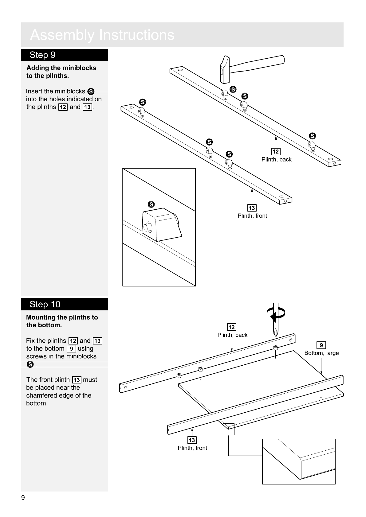
Step 9
e
m
b
l
y
I
n
s
t
r
u
c
t
i
on
s
Adding the miniblocks
to the plinths
Inser
t the miniblocks
into the holes indicated on
the plinths
12
.
and
13
N
.
N
N
Plinth, fron
N
N
12
Plinth, ba
13
t
ck
N
N
N
Step 10
M
ounting the plinths to
the bottom
Fix the plinths
to the bottom
screws in the miniblocks
N
.
The front plinth
be placed near the
chamfered edge of the
bottom.
.
12
9
13
and
using
mus
13
t
12
13
Plinth, fron
Plinth, ba
t
ck
9
Bottom, lar
ge
9
Page 60

A
ss
e
m
b
l
y
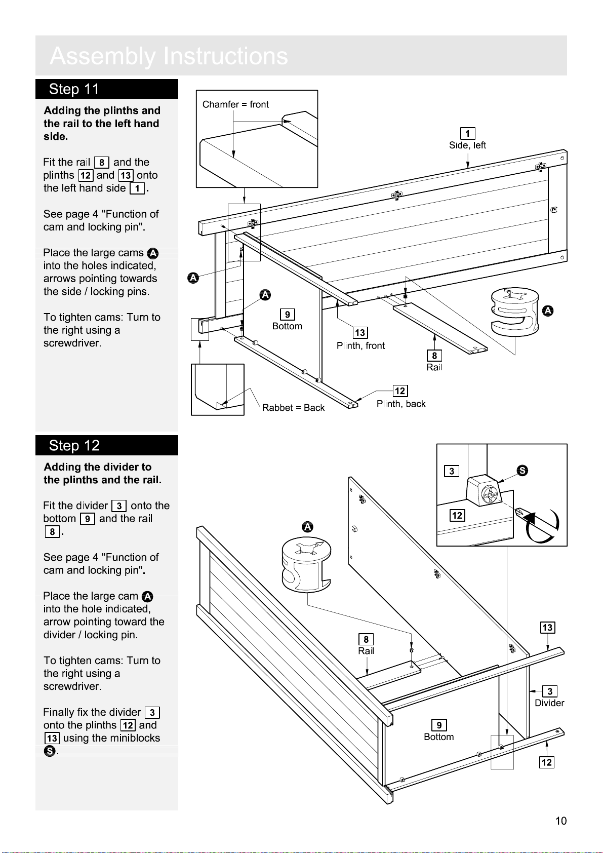
Step 11
Adding the plinths and
the rail to the left
side
.
Fit the rail
12
plinths
the left
See
hand side
page 4 "Function of
cam and locking pin".
8
and
hand
and the
13
onto
1
.
I
n
s
t
r
u
c
t
i
on
Chamfer = front
s
1
Side, lef
t
Place the cams
the holes indicated
A
into
,
arrows pointing towards
the side / locking pins
.
To tighten cams: Turn to
he right using a
t
screwdriver.
Step 12
Adding the divider to
the plinths and the rail
Fit the divider
bottom
.
8
9
and the rail
.
3
onto the
A
A
9
Bottom
R
abbet = Back
A
13
Plinth, fron
Plinth, ba
t
8
Rail
12
ck
3
12
A
N
See
page 4 "Function of
cam and locking pin".
Place the cam
hole indicated, arrow
A
into the
pointing toward the locking
pin
.
To tighten cams: Turn to
he right using a
t
screwdriver.
Finally fix the divider
onto the plinths
13
using the miniblo
.
N
12
and
3
cks
8
Rail
9
Bottom
13
3
Divide
12
10
r
Page 61

A
ss
e
m
b
l
y
I
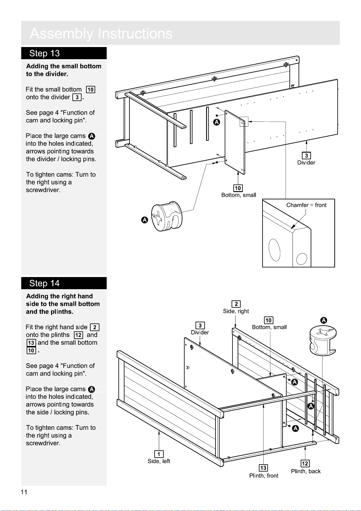
Step 13
Adding the small bottom
to the divider
Fit the small bottom
onto the divider
See
page 4 "Function of
cam and locking pin".
Place the large cams
into the holes indicated
arrows pointing towards
the locking pins
.
10
.
3
A
,
.
n
s
t
r
u
c
t
i
on
s
A
3
Divide
r
To tighten cams: Turn to
he right using a
t
screwdriver.
Step 14
Step 14
Adding the right
side to the small bottom
hand
and the plinths.
Fit the right
onto the plinths
13
and the small bottom
.
10
hand side
12
and
10
Bottom, sma
A
2
3
Divide
r
2
Side, righ
ll
t
10
Bottom, sma
Chamfer = front
A
ll
See
page 4 "Function of
cam and locking pin".
Place the large cams
into the holes indicated
arrows pointing towards
the locking pins
.
To tighten cams: Turn to
he right using a
t
screwdriver.
11
A
,
1
Side, lef
t
13
Plinth, fron
t
A
A
A
12
Plinth, ba
ck
Page 62

A
ss
e
m
b
Step 15
M
ounting the magnets
to the top.
Fix the m
the top
D
into the pre-drilled
holes.
agnets
7
using screws
H
l
y
to
I
n
s
t
r
u
c
t
i
on
s
7
T
op
D
D
D
H
H
H
Front edge
It is important that t
m
agnetic part points
towards the front edge of
the top.
he
Step 16
M
ounting the top onto
the sides and divider.
7
Press the top
sides
divider
1
&
.
3
onto the
2
and the
D
H
Front edge
1
Side, lef
t
Fix the top using screws
P
and allen key
thr
ough the holes
indicated
.
Q
2
Side, righ
t
3
Divide
r
P
P
P
P
P
Q
T
7
op
P
12
Page 63

A
ss
e
Step 17
m
b
l
y
I
n
s
t
r
u
c
t
i
on
s
Adding the back to the
carcass.
Place the back
19
into
the rabbet of the top
2
and the side
Ensure that there is no
gap betw
back, nor betw
top
and the back.
Fasten the back with
G
nails
al
The
angle betw
top
and the side must be
.
een the side
een the
ong the top
een the
90 degrees.
To accomplish this
ensure tha
gap betw
the back
Fasten the back with
nails
t there is no
een the side &
.
G
al
ong the sides.
,
7
.
G
G
G
Back
2
7
T
op
R
abbet = Back
7
2
17
90
7
17
G
o
R
abbet = Back
G
1
G
Step 18
Adding the back & the
joining strip to the
carcass.
Place the joining strip
onto the back.
Place the back
the rabbet of the top
1
and the side
Ensure that there is no
gap betw
back, nor betw
top
and the back.
Fasten the back with
G
nails
al
and bottom.
Fix the back onto the
s
upport rail
screws
D
.
een the side &
een the
ong the side
8
using
into the
pre-drilled holes
19
.
into
7
V
D
G
G
17
V
7
T
op
V
17
Joining stri
2
17
p
17
Back
D
G
G
8
G
1
G
13
Page 64

A
ss
e
m
b
Step 19
Drawer assembly.
Fix the drawer sides
a
:
15
drawer back
screws
and
F
.
16
to the
17
using
l
y
I
n
s
t
a
F
r
u
:
c
t
i
on
s
16
15
17
F
F
F
Slide the drawer
b
:
bottom
18
into the
grooves of the drawer
frame
.
c
:
Screw the locking pins
B
into the holes indicated
14
.
.
16
into
,
.
Do
on the drawer front
Note:
Insert locking pin
B
as far as shown
not over tighten
Press the drawer front
d
:
14
onto the drawer
sides
Place the cams
the holes indicated
15
and
.
A
arrows pointing towards
the drawer fron
t / locking
pins.
To tighten cams: Turn to
he right using a
t
screwdriver.
"Function of cam
locking pin" see page 4
and
.
s
b
c
d
:
:
:
B
14
18
B
B
B
B
A
16
14
A
15
A
17
B
Fix the k
e
:
drawer front
F
screw
R
epeat with remaining
drawer.
.
nob
I
to the
14
using
e
:
I
14
F
14
Page 65
A
ss
e
Step 20
m
b
l
y
I
n
s
t
r
u
c
t
i
on
s
Adding the shelves
hanging rail and the
drawers
Lower the
into the
.
J
Place the shelf supports
O
indicated
Lower the shelves
onto the shelf supports.
Slide the drawer onto the
drawer runners
.
hanging rail
hanging rail cups
into the holes
.
.
, the
11
M
M
H
anging rail
11
Shel
M
J
f
O
O
11
O
O
O
11
O
O
15
Page 66

A
ss
e
m
b
l
y
A
ss
e
m
b
l
y
I
I
Step 21
M
ounting the cup
hinges to the
Fix the cup hi
he holes indicated on the
t
doors
Attach the hinges using
screws
indicated
4
and
.
6
D
into the holes
.
doors
nges
5
.
K
into
and
n
n
s
t
s
t
r
u
r
u
c
t
c
t
i
on
i
on
D
s
s
K
6
Door, righ
t
D
D
K
D
D
K
K
D
K
D
K
K
Step 22
M
ounting the knobs to
the
doors
.
5
Door, lef
F
t
4
Door, sma
ll
F
D
4
K
Door, sma
DD
ll
K
Fasten the k
the
doors
6
and
using screws
nobs
4
and
I
to
5
F
.
I
5
I
F
I
Door, righ
Door, lef
6
t
t
16
Page 67

A
ss
e
m
b
l
y
I
Step 23
M
ounting the
the carcass
W
hen placing the
he m
agnetic catch plates
t
must be a
doors
.
a
:
Place the adjustmen
hole of the cup hinge a
t
he level of the fixing
screw. Push the cup
hinge towards the cross
place - placing the fixing
screw in the wider part of
the adjustment hole.
Important:
!
all three of the
fixing screws.
b
:
Push the
hinge inwards - placing
the fixing screw in the
narrow
adjustment hole
doors to
.
t the top of the
Ensure you catch
door / cup
end of the
doors
.
,
t
t
n
s
t
r
u
c
t
i
on
s
a
:
Cro
ss
plat
Adjustment
hol
b
:
e
e
Fixing scre
Adjusti
screw
w
ng
c
:
Tighten the fixing
screws of all three of the
cross plates
.
c
:
17
Page 68
A
ss
e
m
b
l
y
I
n
s
t
r
u
c
t
i
on
s
Step 24
Adjusting the
Make sure the wardr
is placed on a level
surface before you
to adjus
Right or left:
Loosen the fixing screw.
1.1
doors
t the hi
Fixing scre
.
begin
nges.
obe
w
To adjus
the left
adjusting screw to the right.
1.2
t the
door towards
hand side - turn the
Adjusting screw
To adjus
he right hand side - turn the
t
adjusting screw to the left.
1.3
t the
door towards
Adjusting screw
1
2
3
Continue adjustment - see 2
or tighten the fixing screw of
the cross plate
1.4
s
Cross plat
-
e
Forwards or backwards
Loosen the fixing screw.
Fixing scre
Up or down
Loosen the two screws of each cro
plate, but only as much as it will allow
the cross plate to move up
w
:
E
E
:
and down
.
Push the cup hinges / the
to adjus
edge of the sides
t. The door should level with the front
.
2.22.1
Adjustment hol
ss
Adjus
t the cross plate
e
door back or fort
/
door.
Fixing scre
Tighten the fixing screws of all the cro
h
plates.
2.3
Fixing scre
Tighten the screws
plates.
3.33.23.1
Cross plat
w
e
w
E
of all the cross
E
ss
Cross plat
e
Cross plat
e
18
Page 69
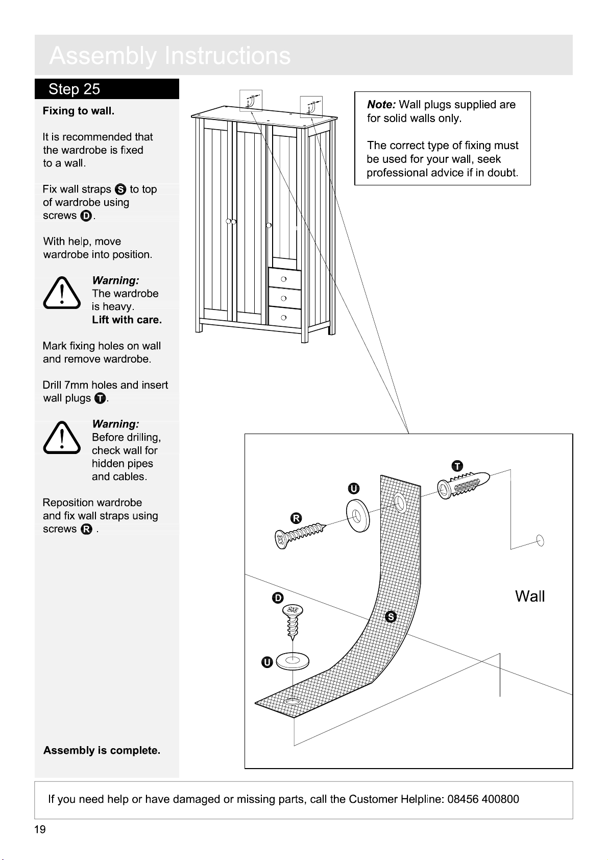
A
ss
e
m
b
Step 25
Fixing to wall
It is recomm
the wardrobe is fixed
to a wall.
Fix wall straps
of wardrobe usi
screws
D
.
.
ended tha
S
to t
ng
l
y
t
op
I
n
s
t
r
u
c
t
i
on
s
Note:
Wall plugs s
for solid walls only
The correct type of fixing must
be used for your wall, seek
professi
onal advice if in
upplied are
.
doub
t.
With help, move
wardr
obe into position
The wardr
!
!
is heavy.
Mark fixing holes on wall
and remove wardrobe
Drill 7mm holes and inser
wall plugs
Before drilling,
!
!
check wall fo
hi
R
eposition wardrobe
and fix wall straps usi
R
screws
.
Warning:
obe
Lift with care
T
.
Warning:
dden pipe
and cables
.
ng
.
.
.
r
s
t
T
U
R
Assembly is complete
If you need help or have dam
19
.
D
S
U
aged or missing parts, call the Customer Helpline: 08456 400800
Wall
Page 70

General Purpo
se” wall plug
“
Cavity
Fixing” wall plug
“ Hammer Fixing” wall plug
Care &
in and around the home. or screws do not become loose.
A Guide to
Important note:
If plastic wall plugs
are supplied with your
product:
- these are only suitable for
use in masonry walls.
If you are in ant double about
the correct wall plugs for
your wall, seek professional
advice.
Failure of the product due to
using incorrect fixings is the
responsibility of the installer.
-
Wall Mouting & Fixings
Check that there are no hidden wires or pipe etc
Important
: When drilling into walls always
Make sure that the screws and wall plugs being used
are suitable for supporting your unit. Consult a qualified
tradesperson if you are unsure.
Hints:
1: General rule: Always use a larger screwand wall plug
if you are not sure.
2: Ensure you use the recommended drill bit to match the wall
plug and hole size..
3: Ensure you drill the hole horizontally, do not force the drill or
enlarge the hole.
4: Take extra care when drilling high walls, ceilings and ceramic
tiles. Ensure wall plus are inserted beyond the thickness of
the ceramic tiles to avoid the tiles splitting or cracking.
5: Ensure wall plugs are well fitted and are a tight fit in the
drilled hole.
Types of walls
No 1“
Generally aerated blocks should not
be used to support heavy loads, use
a specialist fitting in this case. For light
loads, general purpose wall plugs can
be used.
No 2 “ Plasterboard” wall plug
For use when attaching light loads on
to plasterboard partitions.
You can use one of the following types of wall plug if your walls are ma
of brick, breeze block, concrete, stone or wood.
No 3
For use with plasterboard partitions or
hollow wooden doors.
No 4” Cavity Fixing – Heavy duty”
wall plug
For use when fitting or supporting
heavy loads such as shelving, wall
cabinets and coat racks.
No 5
For use with walls stuck with
plasterboard.The hammer fixing allows
it to be fixed to the wall rather than the
plasterboard. Always check the fixing
is secure to the retaining wall.
No 6 “ Shield Anchor” wall plug
Heavy Loads
For use with heavier loads such as TV
& HiFi speakers and satelite dishes etc
Safety: Always check the fitting Fitting: From time to time check
Maintenance
and location to ensure your safety the fitting to ensure the wall plugs
Page 71
D
ear Customer
.
Please note tha
t the pr
oduct you have purchased is a
natural living timber.
Just like nature itself, wood varies in s
Knots, vein patterns, resin pockets
contribute to giving the piece of furniture its beauty and
form - a natural part of solid wood
Alt
hough the tree has been cut down
alive
temperatures, light, humidity, dr
I
l
happens in warm
expands
The colour of the w
and therefore w
ill reac
t to high
ought and time
n cold
and dry periods
, the wood contracts which may
ead to small cracks in the piece of furniture. The reverse
and humid periods where the w
and this may result in slight
ood also changes with time
hape and colour
and colour differences
.
and dried, it is still
and low
.
ood
unevenness.
,
.
particularly if the furniture is place in a light place. This
is a natural process
furniture m
ade of solid w
and part of owning a piece o
ood
.
f
21
Any flexing that has occurred during transport will
re-correct it self once this product is correctly assembled.
Tighten all joints of the furniture after six months.
Please k
use
eep these instructions in a safe place for future
.
 Loading...