

Page 1
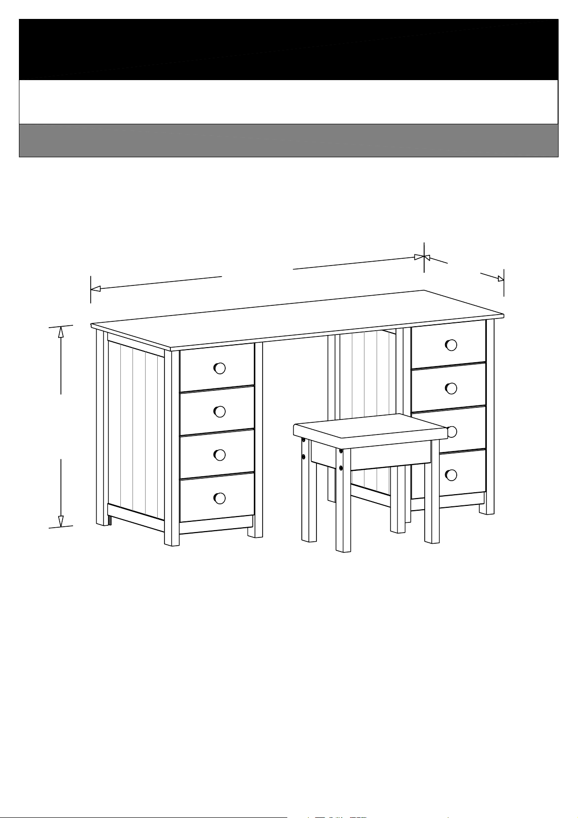
Scandinavia
Dressing table w. 8 drawers + stool
740mm
1400mm
580mm
Page 1 of 12
Scandinavia dressing table w. 8 drawers + stool
Page 2
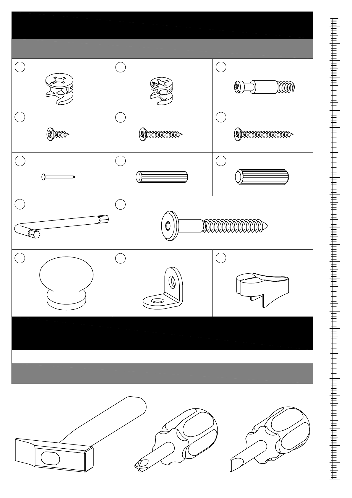
Please sort out all parts before you begin to assemble the item.
This to make sure you always use the correct part.
Fittings contained in the box.
A
D
20 pcs.
8 pcs.
Cam - ø15 x 12mm
Screw - ø3,5 x 12mm
B
E
32 pcs.
32 pcs.
Cam - ø12 x 10,5mm
Screw - ø3,5 x 25mm
C
F
52 pcs.
40 pcs.
Bolt - ø6,5 x 24/11mm
Screw - ø3,5 x 35mm
MM
270
260
250
240
230
220
210
200
30 pcs.
G
1 pcs.
K
8 pcs.
M
Knob
ø40 x 30mm
Nail - 1,2 x 20mm
Allen key - 4mm
H
L
N
4 pcs.
8 pcs.
4 pcs.
Dowel - ø6 x 30mm
Screw - ø7 x 60mm
Angle - 16x20x20mm
Hazard Warning !
J
P
4 pcs.
1 pcs.
Dowel - ø8 x 30mm
Nail guide
190
180
170
160
150
140
130
120
110
100
90
Keep small components out of the reach of children.
Fittings A, B, C, D, E, F, G, H, J, L and N are shown in their a ctual dimensions.
Tools needed.
Page 2 of 12
Scandinavia dressing table w. 8 drawers + stool
80
70
60
50
40
30
20
10
0
Page 3
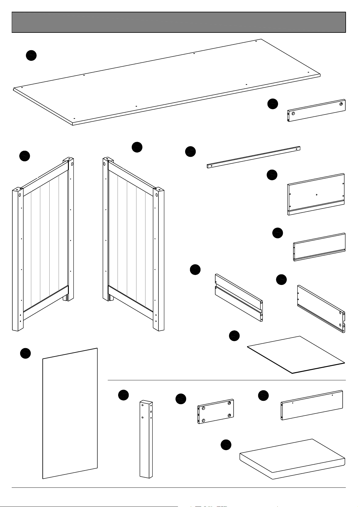
Wooden parts contained in the box.
Top
1
1 pcs.
1400 x 580mm
Side, right
2
2 pcs.
Side, left
3
2 pcs.
16 pcs.
Drawer runner
4
521 x 16mm
5
2 pcs.
6
8 pcs.
Plinth
318 x 55mm
Drawer front
11
2 pcs.
Back
m
m
0
5
5
x
6
2
7
m
m
0
5
5
x
6
2
7
Drawer side, left
8
8 pcs.
442 x 107mm
Drawer bottom
10
8 pcs.
Drawer back
7
8 pcs.
9
8 pcs.
439 x 297mm
314 x 157mm
286 x 92mm
Drawer side, right
442 x 107mm
m
m
6
3
3
x
0
8
6
12
4 pcs.
Stool leg
m
m
5
5
x
6
8
3
13
2 pcs.
Page 3 of 12
End rail
194 x 90mm
15
1 pcs.
Side rail
14
2 pcs.
340 x 90mm
Seat
450 x 350mm
Scandinavia dressing table w. 8 drawers + stool
Page 4
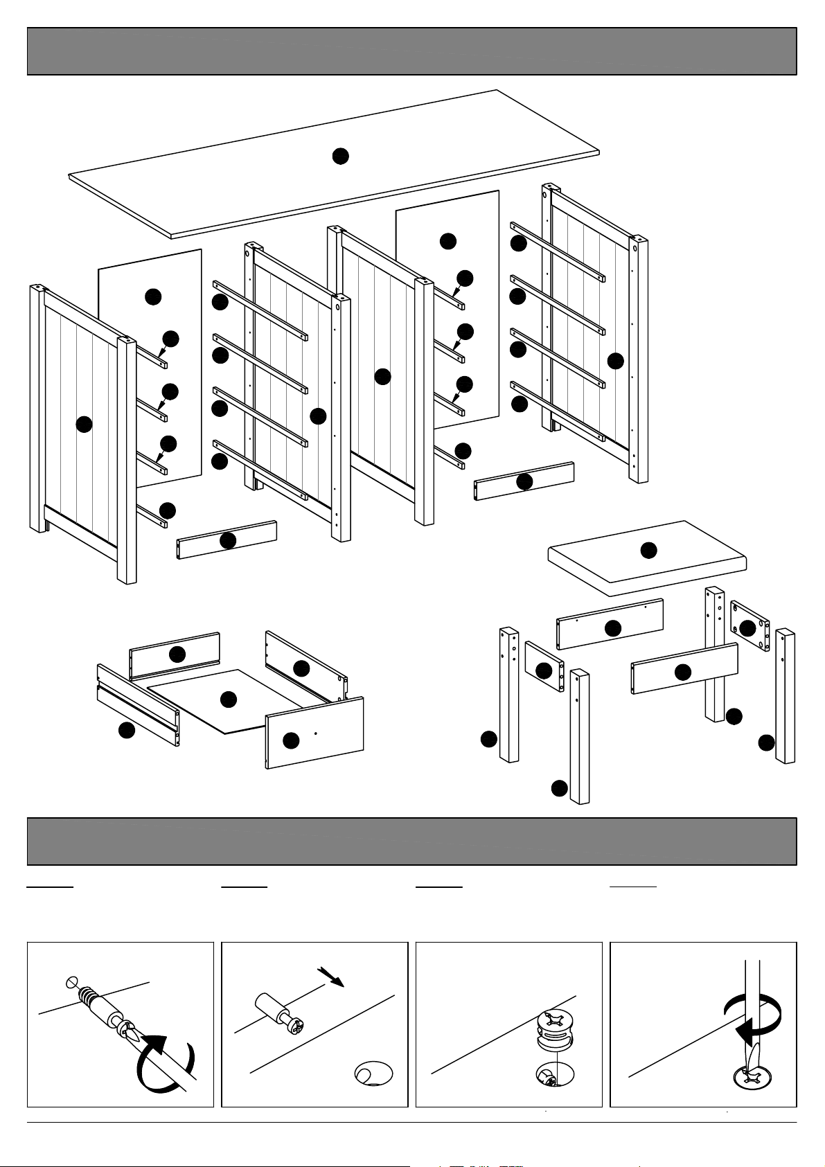
Key diagram.
1
11
4
11
4
4
2
4
4
4
4
4
2
4
4
5
3
4
4
4
4
4
4
5
14
3
15
13
7
9
10
8
6
Function of cam & bolt.
Step 1:
Fix the bolt to the
wooden panel.
1
Step 2:
Push the wooden panel
with the attached bolt onto
the other wooden panel.
2
x 8
13
12
12
Step 3:
Place the cam into the
hole, arrow pointing
towards the bolt.
Step 4:
Tighten: Turn the cam to
the right.
14
12
12
34
Page 4 of 12
Scandinavia dressing table w. 8 drawers + stool
Page 5
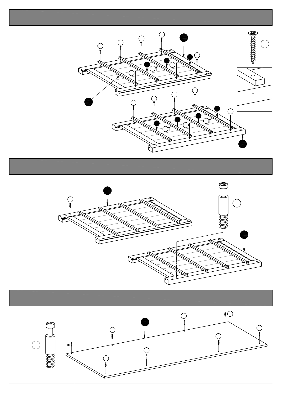
1. Fixing the drawer runners to the sides.
Fix the drawer runners
"4" to the sides "2" and
"3", using screws "E".
Screw the screw in until
the screw head is sunk
and flush with the wood.
4
16 Pcs.
E
Drawer runner
E
E
4
E
E
E
E
E
4
2. Mounting the bolts to the sides.
Side, left
2
2 Pcs.
E
4
E
E
E
4
E
4
4
4
E
E
E
3
2 Pcs.
E
32 Pcs.
Fig. 1.1
Side, right
Screw the bolts "C" into
the holes indicated on
the sides "2" and "3".
C
2
2 Pcs.
Side, left
3. Mounting the bolts to the top.
Screw the bolts "C" into
the holes indicated on
the top "1".
C
1
Top
C
4 Pcs.
Side, right
3
2 Pcs.
C
C
C
C
C
8 Pcs.
C
C
Page 5 of 12
Scandinavia dressing table w. 8 drawers + stool
Page 6
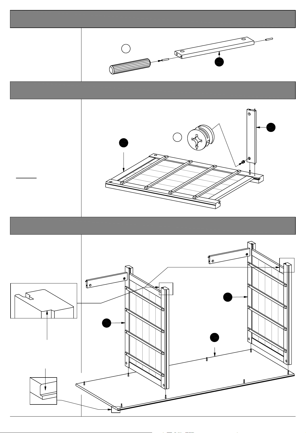
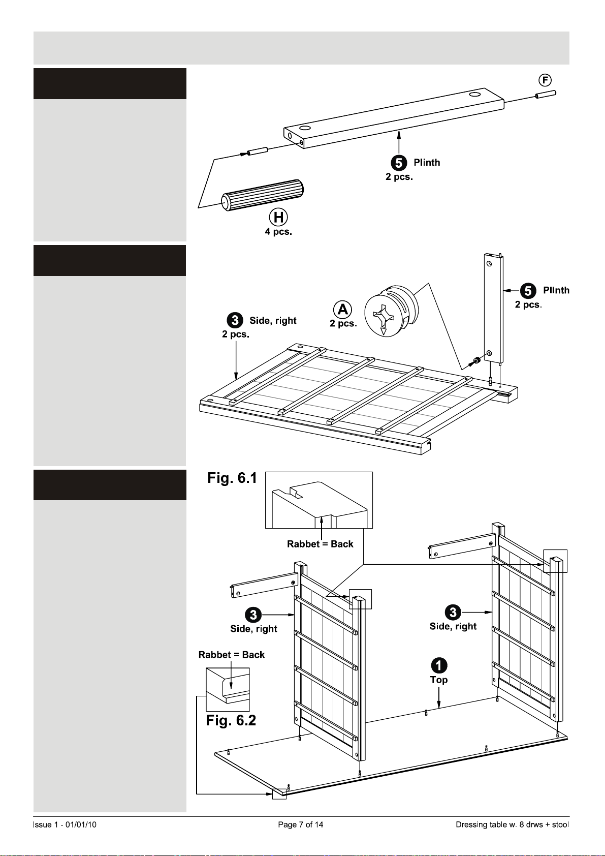
4. Inserting the dowels to the plinth.
Knock the dowels "H"
into the holes indicated
on the plinths "5".
H
4 Pcs.
5
2 Pcs.
Plinth
5. Mounting the plinth to the right hand side.
Press the plinths "5"
onto the right hand
sides "3".
See page 4 "Function of
cam & bolt".
Place the cam "A" into
the hole indicated, arrow
pointing towards the
side / bolt.
3
2 Pcs.
Side, right
A
2 Pcs.
5
2 Pcs.
Plinth
Tighten:
Turn the cam to the
right.
6. Adding the right hand side to the top.
Lower the right hand
sides "3" onto the top "1".
DONT fix the sides to the
top until fig. 8. See page 7.
Fig. 6.1
Rabbet = Back
3
Side, right
3
Side, right
1
Top
Rabbet = Back
Fig. 6.2
Page 6 of 12
Scandinavia dressing table w. 8 drawers + stool
Page 7
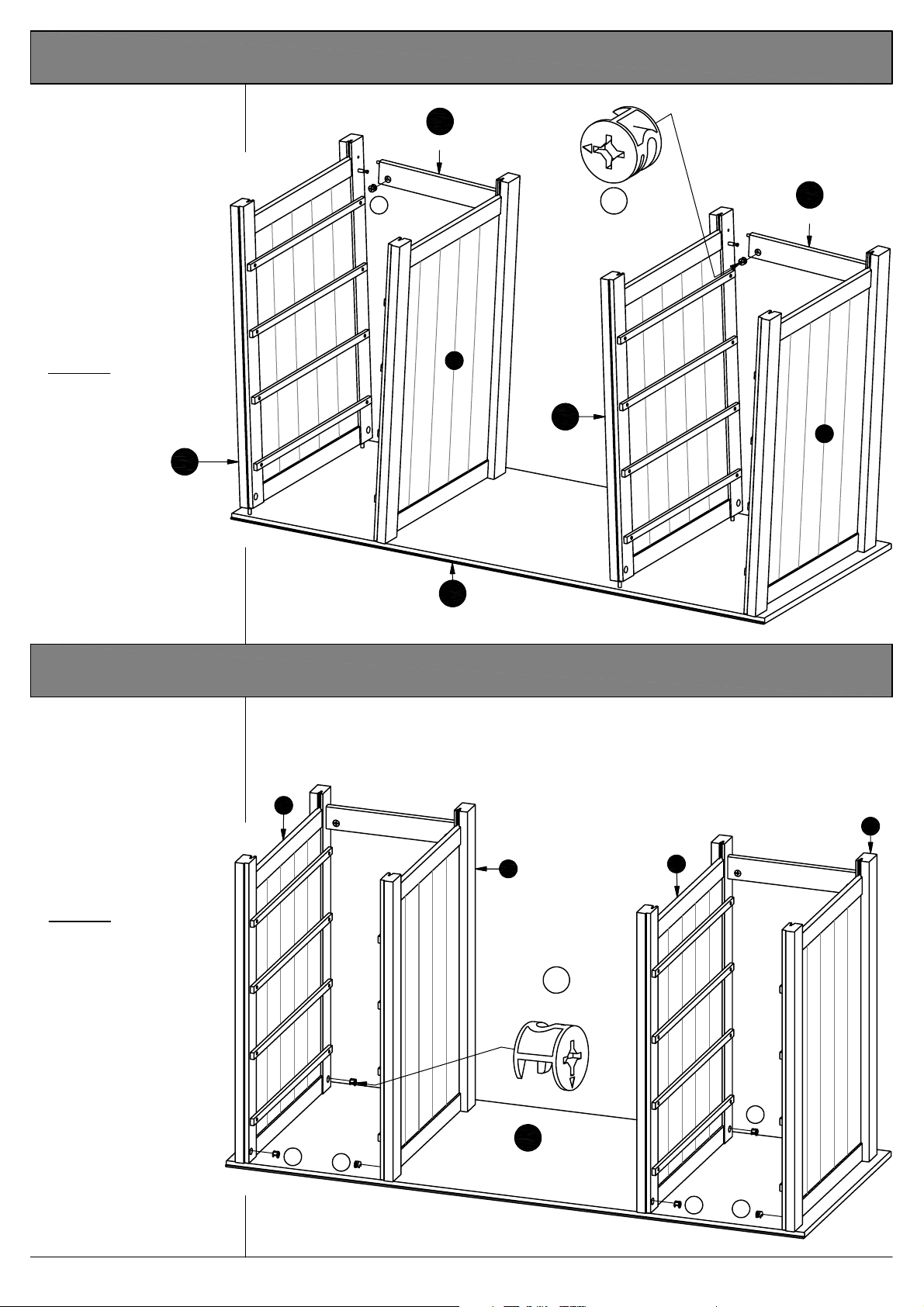
7. Mounting the left hand side to the plinth.
Lower the left hand
sides "2" onto the top
"1".
Press the sides onto
the plinths "5".
See page 4 "Function
of cam & bolt".
Place the cam "A" into
the hole indicated,
arrow pointing
towards the side / bolt.
A
5
Plinth
A
2 Pcs.
5
Plinth
Tighten:
Turn the cam to the
right.
3
2
Side, left
1
Top
8. Fixing the sides to the top.
Fix the sides "2" and
"3" onto the top "1".
See page 4 "Function
of cam & bolt".
Place the cam "A" into
the hole indicated,
arrow pointing
towards the bolt.
2
3
2
Side, left
3
3
2
Tighten:
Turn the cam to the
right.
A
8 Pcs.
A
1
A
A
Page 7 of 12
Top
A
Scandinavia dressing table w. 8 drawers + stool
A
Page 8
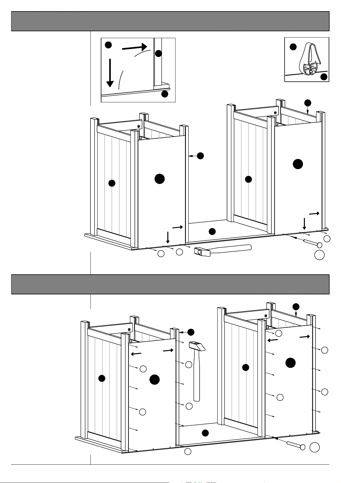
9. Adding the back to the table - 1.
Place the back "11"
into the rabbet of
the top "1" and the
side "3".
See fig. 9.1
Ensure that there is
NO GAP between
the right hand side
"3" and the back
"11" , NOR between
the top and the
back.
Fasten the back with
nails "G" along the
Top. Use the nail
guide "P" as shown.
Fig. 9.2
11
Fig. 9.1
11
3
90a
1
Fig. 9.2
1
3
3
11
Back
2
11
Back
2
G
G
10. Adding the back to the table - 2.
The angle between
the top and the
side must be 90
degrees. Fig. 9.1
To accomplish
this, ensure that
there is NO GAP
between the right
hand side "3" and
the back "11".
Fasten the back
with nails "G"
along the sides.
Use the nail guide.
G
2
11
Back
G
3
G
G
1
G
G
6 Pcs.
3
G
G
2
11
Back
G
G
Page 8 of 12
1
G
Scandinavia dressing table w. 8 drawers + stool
G
24 Pcs.
Page 9
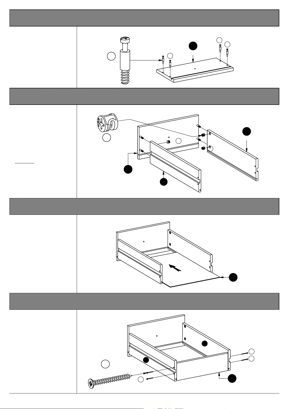
11. Mounting the bolts to the drawer front.
Screw the bolts "C" into
the holes indicated on the
drawer front "6".
C
32 Pcs.
6
C
8 Pcs.
C
C
12. Mounting the drawer sides to the drawer front.
Press the drawer sides
"9" and "8" onto the
drawer front "6".
Place the cams "B" into
the holes indicated,
arrows pointing towards
the drawer front / bolts.
Tighten:
Turn the cam to the
right.
"Function of cam & bolt"
see page 4.
B
32 Pcs.
B
B
6
8 Pcs.
9
8 Pcs.
8
8 Pcs.
13. Sliding the drawer bottom into the drawer frame.
Slide the drawer bottom
"10" into the grooves of
the drawer frame.
10
8 Pcs.
14. Mounting the drawer back to the drawer frame.
Place the drawer
back "7" in between
the drawer sides "8"
and "9".
Fix the drawer back
using screws "F" into
the holes indicated.
9
F
32 Pcs.
F
Page 9 of 12
8
7
8 Pcs.
Scandinavia dressing table w. 8 drawers + stool
F
F
Page 10
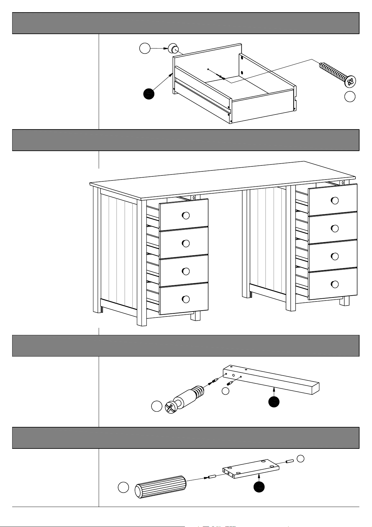
15. Mounting the knobs to the drawer front.
Fix the knobs "M" to the
drawer front using
screws "F".
M
8 Pcs
6
Drawer front
16. Adding the drawers to the table.
Slide the drawers onto
the drawer runners.
F
8 Pcs.
17. Mounting the bolts to the stool legs.
Screw the bolts "C"
into the holes indicated
on the stool legs "12".
C
C
8 Pcs.
18. Inserting the dowels to the end rail.
Knock the dowels "J"
into the holes indicated
on the end rails "13".
J
4 Pcs.
Page 10 of 12
Stool leg
12
4 Pcs.
J
End rail
13
2 Pcs.
Scandinavia dressing table w. 8 drawers + stool
Page 11
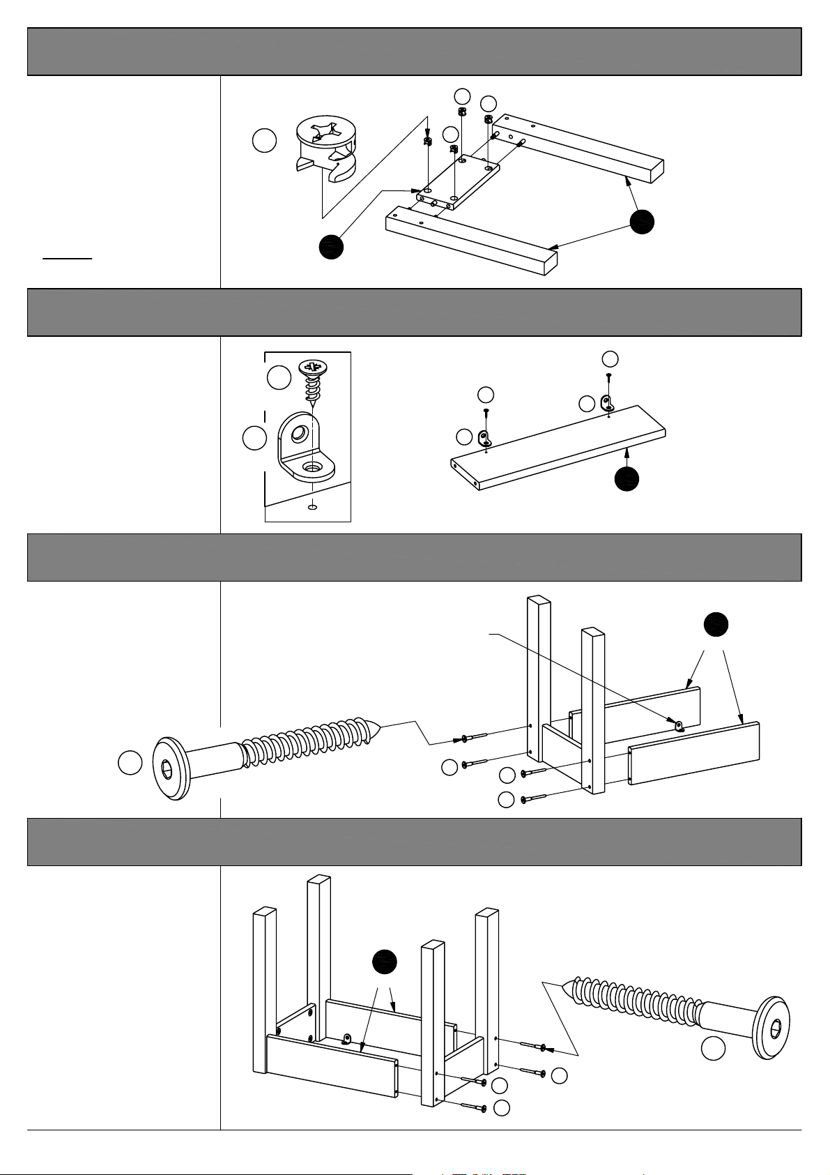
19. Mounting the stool legs to the end rails.
Press the stool legs "12"
onto the end rail "13".
See page 4 "Function of cam
& bolt".
Place the cam "A" into the
hole indicated, arrow
pointing towards the bolt.
Tighten:
Turn the cam to the right.
A
8 Pcs.
13
2 Pcs.
End rail
A
A
A
20. Fixing the angles onto the side rails.
Fix the angles "N" onto the
side rails "14" using screws
"D" into the pre-drilled
holes.
The angles must be turned
exactly as shown.
4 Pcs.
N
4 Pcs.
D
D
N
Fig. 16.1
N
12
4 Pcs.
D
14
2 Pcs.
Stool leg
Side rail
21. Mounting the side rails onto the stool legs - 1.
Press the side rails "14"
onto the stool legs "12".
Note the angles.
Fix the siderails using
screws "L" and allen key
"K" through the holes
indicated.
L
4 Pcs.
Note the angles.
L
L
L
22. Mounting the side rails onto the stool legs - 2.
Press the stool legs "12"
onto the side rails "14".
Fix the siderails using
screws "L" and allen key
"K" through the holes
indicated.
14
Side rail
14
2 Pcs.
Side rail
Page 11 of 12
L
L
L
L
Scandinavia dressing table w. 8 drawers + stool
4 Pcs.
Page 12
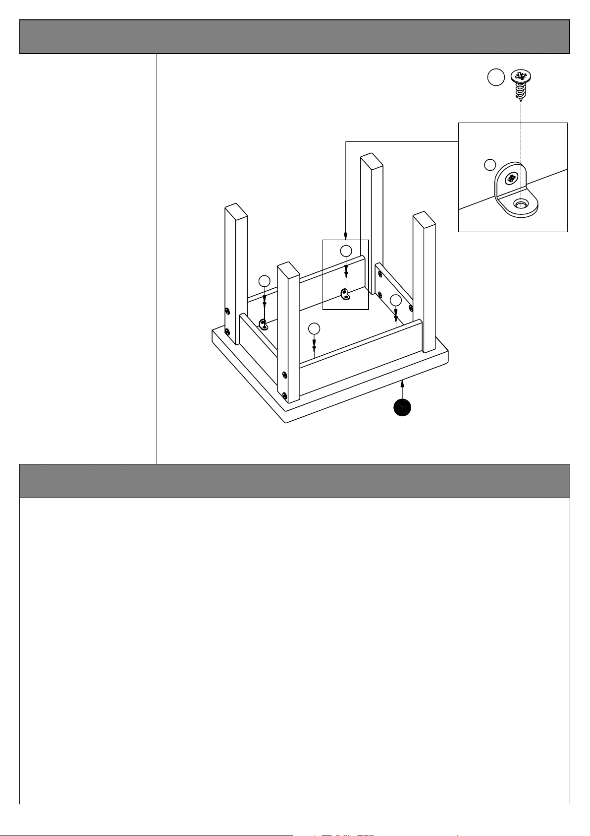
23. Adding the seat to the stool.
Fix the side rails "14"
onto the seat "15"
using screws "D"
through the angles.
See fig. 23.1
D
4 Pcs.
N
D
D
D
D
15
Seat
Dear Customer.
Please note that the product you have purchased is a natural living timber.
Fig. 23.1
Just like nature itself, wood varies in shape and colour. Knots, vein patterns, resin pockets
and colour differences contribute to giving the piece of furniture its beauty and form - a
natural part of solid wood.
Although the tree has been cut down and dried, it is still alive and therefore will react to high
and low temperatures, light, humidity, drought and time.
In cold and dry periods, the wood contracts which may lead to small cracks in the piece of
furniture. The reverse happens in warm and humid periods where the wood expands and this
may result in slight unevenness.
The colour of the wood also changes with time, particularly if the furniture is placed in a light
place. This is a natural process and part of owning a piece of furniture made of solid wood.
Any flexing that has occurred during transport will re-correct it self once this product is
correctly assembled.
Tighten all joints of the furniture after six months. Please keep these instructions in a safe
place for future use.
Page 12 of 12
Scandinavia dressing table w. 8 drawers + stool
Page 13

Scandinavia
- Dressing table w. 8 Drws + stool
Assembly Instruction - Please keep for future reference 642/3746
Dimensions
Important
If you need help or have damaged or missing parts, call the Customer Helpline: 08456 400800
Issue 1 - 01/01/10
- Please read these instr uc tions fully before star ting assembl y
P
age 1 of
14
Dressing table w. 8 drws + stoo
l
Page 14

Safety and Care Advice
Important
Check you have all t
com
ponents and tools listed
pages 2
Remove all fittings from t
plastic bags
into their gr
Keep children
and 3
- Please read these instructions fully before starting assembly
he
on
.
he
and s
eparate the
oups.
and animal
m
s
away from the work area, small
parts could choke if swallowed
.
Make sure you have enough
space to layou
starting
.
t the parts before
Care and m aintenance
Only clean using a damp cloth
and mild detergent, do no use
bleach or abrasive cleaners.
Do not stand on the product,
this could cause dam
Assemble the item as clos
age
.
e
to its final position (in the same
room) as possible.
Assemble on a soft leve
l
surface to avoid damaging the
unit or your floor.
Parts of the assembly w
easier with 2
From time to time check that
people
ill be
.
there are no loose screws on
this unit.
We do no
recommend the
use of powe
dr
ill/drivers
inserting screws
t
r
for
,
as this could damage the unit.
Only use
hand screwdrivers
.
Dispose of all packaging
carefully
This product should not be
and res
ponsibly.
discarded with household
waste. Take to your local
authority waste disposal centre.
Issue 1 - 01/01/10
P
age 2 of
14
Note:
if r
equired the nex
t
page can be cut out and used
as reference throughou
assembly. K
these instructions for future
reference.
eep this page wit
Dressing table w. 8 drws + stoo
t t
he
h
l
Page 15

Component s - Panels
Please check you have all the fittings listed below
T
op
1 pcs.
1400 x 580
mm
2 pcs.
Plinth
318 x 55
mm
2 pcs.
Side, lef
t
2 pcs.
Side, righ
t
Drawer runne
16 pcs.
r
Drawer front
512 x 16
mm
8 pcs.
314 x 157
Drawer back
mm
8 pcs.
mm
550
x
726
mm
550
x
726
8 pcs.
Drawer side, left
442 x 107
mm
Drawer side, right
8 pcs.
442 x 107
286 x 90
mm
mm
Back
2 pcs.
mm
336
x
680
Issue 1 - 01/01/10
4 pcs.
Stool leg
mm
55
x
386
2 pcs.
P
age 3 of
End ra
14
Drawer bottom
8 pcs.
il
194 x 90
1 pcs.
mm
Seat
439 x 297
2 pcs.
mm
Side rail
340 x 90
450 x 350
Dressing table w. 8 drws + stoo
mm
mm
l
Page 16

If you have damaged or missing components,
Components - Fitting s
call the
Please check you have all the fittings listed below
Note:
The quantities below are correct am
fittings may be supplied than are r
equired.
oun
t to complete the assembly
Customer Helpline : 08 456 40 0800
. In some cases mor
e
A
20 pcs.
Cam -
D
8 pcs.
G
30 pcs.
J
1 pcs.
15 x 12
∅
mm
Screw -
∅
3,5 x 12
Nail - 1,2 x 20
Allen key - 4
mm
mm
mm
B
32 pcs.
Cam -
E
32 pcs.
H
K
8 pcs.
∅
12 x 10,5
4 pcs.
mm
Screw -
Dowel -
4 x 20
∅
6 x 30
∅
mm
mm
C
52 pcs.
∅
6,5 x 24/9
F
40 pcs.
I
4 pcs.
L
4 pcs.
Locking pi
mm
Screw -
Dowel -
n
∅
3,5 x 35
8 x 30
∅
mm
mm
M
8 pcs.
Screw -
To o ls re qu ir ed
Philips screwdrive
(medium & large
Flatblade screwdrive
(medium)
7mm Suitable dr
(for use with wall plug
7 x 60
∅
mm
K
nob
40 x 30
∅
r
)
ill bit
r
)
Angl
mm
Drill
e
16x20x20
0
50
60
40
30
20
10
mm
Sma
ll
hamme
70
90
120
110
80
100
150
130
140
Ruler/tape
measur
r
e
Eye protection
(when using
ha
mmer or glue)
a
Ruler
0
Issue 1 - 01/01/10
- Use this ruler to hel p correctly identi fy the screws
10
5
15
50
55
35
30
25
20
45
40
65
60
70
75
85 95
P
age 4 of
9080
100
105
110
115 125
14
120
130
135
145 155 165
140
Dressing table w. 8 drws + stoo
150
160
170
l
Page 17

Key Diagram.
Key Diagram.
x 8
Function of cam & locking pin.
Step 2
Step 1
:
Fix the locking pin to
the wooden panel.
1
:
Push the wooden panel with
the attac
onto the other wooden panel.
hed locking pin
2
Step 3
:
Place the cam into t
hole, arrow pointing
towards the locking pin
he
3
Step 4
:
Tighten: Turn the cam to
the right.
.
4
Issue 1 - 01/01/10
P
age 5 of
14
Dressing table w. 8 drws + stoo
l
Page 18

Assembly instructions
Assembly of
dressing table
1. Fixing the drawer
runners to the sides.
Fix th e w ood runners "4 " t o
the sides "2" and "3", using
screws "E".
Screw the screw in until the
screw head is sunk and
flush with the wood.
2. Mounting the locking
pins to the sides.
16 pcs.
E
Drawer runne
E
r
E
E
E
E
E
E
E
2 pcs.
E
Side, lef
E
t
E
32 pcs.
E
2 pcs.
Fig. 1.1
Side, righ
C
t
Screw t he loc king pins "C"
into the holes indicated on
the sides "2" and "3".
3. Mounting the locking
pins to the top.
Screw t he locking pins "C"
into the holes indicated on
the top "1".
C
C
4 pcs.
C
8 pcs.
2 pcs.
Side, lef
t
Side, righ
2 pcs.
C
C
t
C
Issue 1 - 01/01/10
P
age 6 of
T
C
C
14
op
C
C
Dressing table w. 8 drws + stoo
C
l
Page 19
Assembly instructions
4. Insert ing th e dowe ls
to the plinth.
Knock the dowels "H" into
the holes indicated on the
plinths "5".
5. Mounting the plinth
to the right hand side.
Press the plinths "5" onto
the right hand side "3".
See page 5 "Function of
cam an d locki ng pi n".
Place the cams "A" into
the hole indicated, arrow
pointing towards the side
/ locking pins.
2 pcs.
H
4 pcs.
Side, righ
t
A
2 pcs.
F
Plinth
2 pcs.
Plinth
2 pcs.
Tighten:
Turn the cam to the right.
6. Adding the right hand
side to the top.
After fixing 5 to , lower
"" "3"
the right hand sides "3"
onto the top "1".
DON’T fix the sides to the
until fig. 8. See page 8.
top
Fig. 6.1
Side, righ
R
abbet = Back
R
abbet = Back
t
Side, righ
T
op
t
Issue 1 - 01/01/10
Fig. 6.2
P
age 7 of
14
Dressing table w. 8 drws + stoo
l
Page 20

Assembly instructions
7. Mounting the left
hand side to the plinth.
Lower the left h and sides
"2" onto th e top "1".
Press the sides onto the
plinths "5".
See page 5 " Functi on of
cam and locking pin".
Place the cams "A" into
the hole indicat ed , ar ro w
pointing towar ds the side
/ locki ng pins.
Tighten:
Turn the cam to the right.
Side, lef
t
Plinth
A
Side, lef
A
2 pcs.
t
Plinth
8. Attach sides to the
top.
Fix the side "2" and "3"
onto the top "1".
See page 5 "Function of
cam and locking pin".
Place the cams "A" into the
hole indicated, arrows
pointing towards the
side / locking pins.
Tighten:
Turn the cams to the right.
T
op
A
8 pcs.
A
Issue 1 - 01/01/10
A
A
P
age 8 of
14
T
op
A
A
Dressing table w. 8 drws + stoo
l
Page 21

Assembly instructions
9. Nailing the back to the
top and sides.
Place the back into the
rabbet of the top "1" and
the side "3". See fig. 9.1
Ensure that there is NO
GAP between th e right
hand side "3" and the
back "11", NOR betw een
the top and the back.
Fasten t he b ack wi t h nails
"G" along the top.
The angle between the top
and the side must be 90
degrees.
Fig. 9.1
To accomplish this, ensure
that t here is NO GAP
between the righ t hand
side "3" and the back "11".
Fasten t he b ack wi t h nails
"G" along the sides.
G
R
abbet = Back
G
30 pcs.
G
Back
Fig. 9.1
G
G
T
op
R
abbet = Back
G
G
G
Back
10. Mounting the locking
pins to the drawer front.
Screw the locking pins "C"
into the ho les indica ted on
the drawer front "6".
o
90
Fig. 9.2
C
C
32 pcs.
C
C
8 pcs.
C
Issue 1 - 01/01/10
P
age 9 of
14
Dressing table w. 8 drws + stoo
l
Page 22

Assembly instructions
A
ssembly instruction
11. Mounting the drawer
sides to the drawer front.
Press the drawer sides "8"
and "9" onto the drawer
front "6".
Place the cams "B" into
the holes indicated,
arrows pointing towards
the drawer front / locking
pins.
32 pcs.
B
s
B
B
8 pcs.
Tighten:
Turn the cam to the right.
"Function of cam and
locking pin" see page 5.
12. Sliding the drawer
bottom into the dra we r
front.
Slid e t he drawer bo ttom
"13" into the grooves of the
drawer frame.
8 pcs.
8 pcs.
13. Mounting the drawer
back to the drawer frame.
Place the drawer back "7" in
between the drawer sides
"8" and "9".
Fix the drawer back us i ng
screw "F" into the holes
indicated.
Issue 1 - 01/01/10
F
32 pcs.
8 pcs.
F
F
F
8 pcs.
P
age 10 of
14
Dressing table w. 8 drws + stoo
l
Page 23

Assembly instructions
14. Mounting the knobs
to the drawer front.
Fix the knob "K" to the
drawer front using screws
"F".
Drawer front
15. Adding the drawers
to the table.
Slide the drawers onto the
drawer runn ers.
K
8 pcs.
F
8 pcs.
Assembly of
dressing stool
16. Mounting the locking
pin to the stool legs.
Screw the locking pins "C"
into the ho les indicated on
the stool legs "12 " .
17. Inserting the dowels
to the end rail.
Knock the dowels "I" into
the holes indicated on the
end rails "13".
C
I
4 pcs.
C
8 pcs.
C
Stool leg
4 pcs.
I
End ra
il
2 pcs.
Issue 1 - 01/01/10
P
age 11 of
14
Dressing table w. 8 drws + stoo
l
Page 24

Assembly instructions
18. Mounting t he st o ol
legs to the end rails.
Press the stool legs "12"
onto the end rail "13".
See page 5 "Function of
cam and locking pin".
Place the cams "B" into the
holes indicat e d, ar ro ws
pointing towards the locking
pins.
Tighten:
Turn the cam to the right.
19. Fixing the angles
onto the side rails.
Fix the angle "L" onto the
side rails "14" using
screws "D" into the
pre-drilled holes.
The angels must be turn
exactly as shown.
L
4 pcs.
A
8 pcs.
2 pcs.
D
4 pcs.
End ra
il
A
A
Stool leg
4 pcs.
D
D
L
L
Side rail
2 pcs.
20. Mounting the side
rails onto the stool
legs - 1.
Press the side rails "14"
onto the stoo l le gs "12 ".
Note the angles.
Fix the side rails using
screws "M" and all en key
"J" through the holes
indicated.
Note the
M
M
angles.
Fig. 19.1
Side rail
2 pcs.
M
Issue 1 - 01/01/10
M
4 pcs.
P
age 12 of
14
Dressing table w. 8 drws + stoo
l
Page 25

Assembly instructions
21. Mounting the side
rails onto the stool
legs - 2.
Press the stool legs "12"
onto the side rails "14".
Fix the side rails using
screws "M" and allen key
"J" through the holes
indicated.
M
4 pcs.
Side rail
2 pcs.
22. Adding the seat to
the stool.
Fix the side rails "14" onto
the seat "15" using screws
"D" through the angles.
See fig. 22.1
M
M
M
D
4 pcs.
N
D
If you need help or have dam
Issue 1 - 01/01/10
D
D
D
Seat
Fig. 22.1
aged or missing parts, call the Customer Helpline: 08456 400800
P
age 13 of
14
Dressing table w. 8 drws + stoo
l
Page 26

Please note tha
t the pr
natural living timber.
oduct you have purchased is a
Just like nature itself, wood varies in s
Knots, vein patterns, resin pockets
contribute to giving the piece of furniture its beauty and
form - a natural part of solid wood
Alt
hough the tree has been cut down
alive
and therefore w
temperatures, light, humidity, dr
n cold
I
l
ead to small cracks in the piece of furniture. The reverse
and dry periods
happens in warm
expands
and this may result in slight
The colour of the w
ill reac
t to high
ought and time
, the wood contracts which may
and humid periods where the w
ood also changes with time
hape and colour
.
and colour differences
.
and dried, it is still
and low
.
ood
unevenness.
,
particularly if the furniture is place in a light place. This
is a natural process
furniture m
ade of solid w
and part of owning a piece o
ood
.
f
Issue 1 - 01/01/10
Any flexing that has occurred during transport will
re-correct it self once this product is correctly assembled.
Tighten all joints of the furniture after six months.
Please k
use
eep these instructions in a safe place for future
.
P
age 14 of
14
Dressing table w. 8 drws + stoo
l
Page 27

S
c
and
i
na
v
i
a
-
D
r
e
ss
i
ng
T
ab
l
e
w
.
8
D
r
w
s
+
S
t
oo
l
A
ssembly Instructi
on
s
- Please k
eep for future reference
642/3746
643/6908
Dimension
Width - 140cm
Depth - 58c
Height - 74c
Import
If you need help or have dam
s
m
m
- Please r
an
t
ead these instructions
fully before starting assembly
aged or missing parts, call the
Customer Helpline: 08456 400800
Issue 2 - 01/04/12
Page 28

!
S
Important
a
f
e
t
-
Please r
y
and
C
a
r
e
A
d
v
i
c
e
ead these instructions fully before starting assembl
y
Check you have all t
com
ponents and tools listed
pages 2
Remove all fittings from t
plastic bags
into their gr
Keep children
away from the work area, small
parts could choke if swallowed
Make sure you have enough
space to layou
starting
Only clean using a damp clot
and mild detergen
bleach or abrasive cl
.
Care
and 3
.
and s
oups.
and animal
t the parts before
and maint
he
on
he
eparate the
s
enance
t, do no us
eaners
m
.
e
.
Do not stand on
the pr
oduct, this could
cause dam
Assemble the item as clos
to its final position (in the same
room) as possible.
Assemble on a soft leve
surface to avoid damaging the
un
it or your floor
Parts of the assembly will be
easier with 2
From time to time check tha
h
here are no loose screws
t
this uni
age
t.
.
.
people
.
l
e
on
t
We do no
use of powe
dr
inserting screws
as this could damage the unit.
Only use
Dispose of all packaging
carefully
The maximum safe weight of
user:
110kg
This product should not be
discar
ded with
waste. Take to your loca
authority waste disposal centre
recomm
ill/drivers
hand screwdrivers
and res
ponsibly.
.
household
t
end the
r
for
l
,
.
.
Note:
if r
equired the nex
page can be cut out and used
as reference throughou
assembly. K
these instructions for future
reference.
1
eep this page wit
t
t t
he
h
Page 29

If you have damaged or missing components
C
o
m
ponen
t
s
-
P
ane
l
s
call the
Please check you have all the panels listed below
Customer Helpline: 08456 400800
,
2
Left side x
(72.6 x 55cm)
1
2
3
Right side x 2
(72.6 x 55cm)
Top
(
140 x 58cm
7
)
5
Drawer front x 8
(31.4 x 15.7cm)
Left drawer side x 8
(44.2 x 10.7cm)
Drawer bottom x 8
9
(43.9 x 29.7cm)
4
Plinth x 2
(31.8 x 5.5cm)
Drawer back x 8
6
(28.6 x 9cm)
8
Right drawer side x 8
(44.2 x 10.7cm)
Back x 2
10
(68 x 33.6cm)
11
Stool leg x 4
(38.6 x 5.5cm)
12
End rail x
(19.4 x 9cm)
13
Side rail x 2
(34 x 9cm)
2
14
Seat
(45 x 35cm)
2
Page 30

C
o
m
ponen
t
s
-
F
i
tt
i
ng
s
Please check you have all the fittings listed belo
Note:
may be s
The quantities below are correct am
upplied than are r
A
D
12mm Screw x
G
Large cam x 20
8
equired.
oun
t to complete the assembly
B
E
H
w
Small cam x
32
C
32
Locking pin x
F
35mm Screw x
I
. In some cases more fittings
52
4020mm Screw x
16mm Nail x
J
30
Allen key x 1
M
60mm Screw x
Tools requir
8
ed
Philips screwdrive
(medium & large
Flatblade screwdrive
(medium)
30mm Dowel x
K
N
r
)
r
4
K
nob x 8
Drill
30mm Dowel x
L
521mm Wooden r
0
10
70
50
60
40
30
20
8090100 110
120
4
150
130
140
Angle x
unner x
Sma
ll
hamme
r
Ruler/tape
measur
e
4
16
Ruler
0
3
Suitable drill bit
(for use with wall plug
- Use this ruler to help correctly identify the screws
35
30
5
10
25
15
20
50
45
40
)
55
65
60
75
70
9080
85 95
100
105
110
115 125
120
130
135
145 155 165
140
Eye protection
(when using
ha
mmer or glue)
160
150
a
170
Page 31

C
o
m
ponen
t
s
-
K
e
y
D
1
i
ag
r
a
m
10
10
3
2
4
6
9
7
8
5
2
4
x 8
11
12
3
14
12
13
13
11
11
F
un
c
t
i
on
Step 1
:
Fix the locking pin to
the wooden panel.
1
C
o
f
C
a
m
and
Step 2
:
Push the wooden panel with
the attac
onto the other wooden panel.
hed locking pin
2
Lo
ck
i
ng
Step 3
:
Place the cam into t
hole, arrow pointing
towards the locking pin
3
11
P
A
i
n
he
Step 4
:
Tighten: Turn the cam to
t
he righ
t.
.
4
B
4
Page 32

A
ss
e
m
b
l
y
I
n
s
t
r
u
c
t
i
on
s
A
ssembly of
dre
ssing table
Step 1
Attaching the w
r
unners to the sides.
Fix the w
to the sides
using screws
the holes indicated
ooden r
ooden
unners
2
and
E
thr
.
ough
.
E
E
N
3
,
N
Side, lef
E
E
E
2
t
E
Side, lef
E
E
E
2
t
N
E
N
Side, righ
E
E
3
t
Step 2
M
ounting the locking
pins to the sides
Screw the locking pins
C
into the holes
indicated on the side
2
Note:
C
as far as shown
not over tighten
3
and
Insert locking pin
.
s
.
.
Do
.
s
E E
N
3
Side, righ
C
C
t
2
Side, lef
t
N
C
C
2
Side, lef
t
Side, righ
3
t
5
3
Side, righ
C
t
Page 33

A
ss
e
m
b
l
y
I
n
s
t
r
u
c
t
i
on
s
Step 3
M
ounting the locking
pins to the top.
Screw the locking pins
into the holes indicated
1
on the top
Note:
Insert locking pin
C
as far as shown
not over tighten
.
.
.
Do
s
Step 4
Inserting the dowels to
the plinths
Inser
he holes indicated on
t
the plinths
.
t the dowels
4
.
H
into
C
C
C
C
C
C
4
Plinth
H
T
1
op
C
C
C
C
H
H
Step 5
M
ounting the plinths to
t
he right hand sides.
4
Fit the plinths
the right
See
cam and locking pin".
Place the large cams
into the holes indicated
arrows pointing towards
the side / locking pins
To tighten cams: Turn to
he right using a
t
screwdriver.
hand sides
page 4 "Function o
ont
o
3
.
.
A
,
f
H
3
Side, righ
t
3
Side, righ
4
Plinth
t
A
A
4
Plinth
4
Plinth
6
Page 34

A
ss
e
m
b
l
y
I
n
s
t
r
u
c
t
i
on
s
Step 6
M
ounting the left
sides to the plinths
Fit the left
onto the plinths
See
of cam
Place the large cams
into the holes indicated
arrows pointing towards
the side / locking pins
To tighten cams: Turn to
he right using a
t
screwdriver.
hand sides
page 4 "Function
and locking pin".
hand
.
4
.
.
A
2
,
3
Side, righ
t
4
Plinth
A
2
Side, lef
t
2
Side, lef
A
t
Step 7
Assembling the top to
the sides
Attach the top
the sides
See
cam and locking pin".
Place the large cams
into the holes indicated
arrows pointing towards
the top / locking pins
To tighten cams: Turn to
he right using a
t
screwdriver.
.
2
and
page 4 "Function of
1
onto
.
3
.
A
,
3
Side, righ
A
A
A
T
1
op
t
4
Plinth
A
7
2
Side, lef
t
3
Side, righ
t
2
Side, lef
t
3
Side, righ
t
Page 35
A
ss
Step 8
e
m
b
l
y
I
n
s
t
r
u
c
t
i
on
s
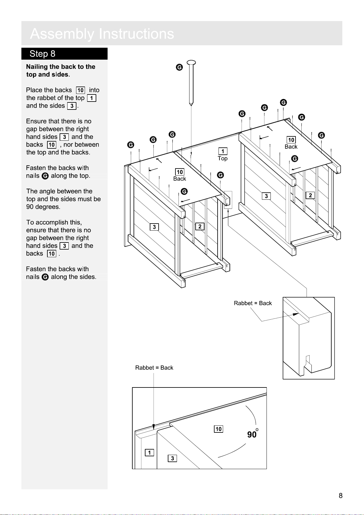
Nailing the back to the
top
and sides.
Place the ba
the rabbet of the top
and the sides
Ensure that there is no
gap betw
hand sides
ba
cks
the top
Fasten the ba
nails
The
top
een the righ
10
, nor betw
and the ba
G
al
ong the top
angle betw
and the sides must be
10
cks
.
3
3
and the
cks
cks with
een the
into
t
een
.
.
90 degrees.
To accomplish this
ensure tha
gap betw
hand sides
ba
cks
t there is no
een the righ
.
10
3
and the
,
t
1
G
G
G
G
G
1
T
op
10
Back
G
3
2
G
G
G
G
10
Back
G
3
G
2
Fasten the ba
G
nails
al
ong the sides.
cks with
R
abbet = Back
10
R
abbet = Back
o
90
1
3
8
Page 36

A
ss
e
m
b
Step 9
Drawer assembly.
Fix the drawer sides
a
:
7
back
F
.
8
and
to the drawer
6
using screws
l
y
I
n
s
t
a
r
u
:
c
F
t
i
on
s
8
F
7
F
F
6
Slide the drawer
b
:
bottom
9
into the
grooves of the drawer
frame
.
c
:
Screw the locking pins
C
into the holes indicated
.
.
5
.
Do
B
,
on the drawer front
Note:
Insert locking pin
C
as far as shown
not over tighten
Press the drawer front
d
:
5
onto the drawer sides
7
and
Place the small cams
into the holes indicated
.
8
arrows pointing towards
the drawer fron
t / locking
pins.
To tighten cams: Turn to
t
he right using a
screwdriver.
"Function of cam
locking pin" see page 4
and
.
s
b
:
9
C
c
:
d
:
B
5
C
C
5
B
C
B
C
7
C
8
6
Fix the knob
e
:
drawer front
screw
R
drawers
9
F
epeat with remaining
.
5
.
K
to the
using
e
:
K
5
F
Page 37

A
ss
e
m
b
l
y
Step 10
Adding the drawers to
the table.
I
n
s
t
r
u
c
t
i
on
s
Slide the drawers onto the
w
ooden r
A
dre
unners
ssembly of
.
ssing stool.
Step 11
M
ounting the locking
pins to the stool legs
Screw the locking pins
into the holes indicated
on the stool legs
Note:
Insert locking pin
C
as far as shown
not over tighten
.
11
.
.
C
.
s
Do
C
11
Stool leg
C
C
C
C
11
Stool leg
Step 12
Inserting the dowels to
the
end rails.
12
.
I
into
nsert the dowels
I
he holes indicated on
t
he end rails
t
C
C
C
I
C
11
Stool leg
12
End ra
I
il
11
Stool leg
12
End ra
I
I
il
10
Page 38

A
ss
e
m
b
l
y
I
n
s
t
r
u
c
t
i
on
s
Step 13
M
ounting the stool legs
to the
end rails.
Press the stool legs
onto the end rails
See
page 4 "Function of
12
11
.
cam and locking pin".
A
Place the large cams
into the holes indicated
arrows pointing towards
,
the stool leg / locking pins
To tighten cams: Turn to
he right using a
t
screwdriver.
Step 14
Fixing the angles onto
the side rails
.
.
A
A
A
11
Stool leg
D
A
12
End ra
il
11
Stool leg
A
D
11
Stool leg
A
A
12
End ra
L
A
il
11
Stool leg
D
L
13
using
onto the
.
.
Fix the angles
side rails
screws
D
into the
pre-drilled holes
The
angels must be turn
exactly as shown
Step 15
M
ounting the side rails
onto the stool legs.
Press the side rails
onto the stool legs
Note the
angles.
Fix the side rails using
screws
J
thr
indicated
M
and allen key
ough the holes
.
13
11
L
D
D
13
Side rail
L
L
Note the
.
angles.
M
M
M
L
13
Side rail
11
Stool leg
13
Side rail
13
Side rail
11
M
Page 39

A
ss
e
m
b
l
y
I
n
s
t
r
u
c
t
i
on
s
Step 16
M
ounting the stool legs
onto the side rails.
Press the stool legs
onto the side rails
Fix the side rails using
screws
J
thr
indicated
M
and allen key
ough the holes
.
13
11
.
M
11
Stool leg
13
Side rail
M
M
M
Step 17
Adding the sea
stool.
Fix the side rails
the sea
screws
angles.
t
D
14
using
thr
t to the
ough the
13
onto
D
L
D
D
D
D
Assembly is complete
If you need help or have dam
.
aged or missing parts, call the
14
Seat
Customer Helpline: 08456 400800
12
Page 40

Dear Customer
Dear Customer
Please note that the product you have purchased is a
natural living timber.
Just like nature itself, wood varies in shape and colour.
Knots, vein patterns, resin pockets and colour differences
contribute to giving the piece of furniture its beauty and
form - a natural part of solid wood.
Although the tree has been cut down and dried, it is still
alive and therefore will react to high and low
temperatures, light, humidity, drought and time.
In cold and dry periods, the wood contracts which may
lead to small cracks in the piece of furniture. The reverse
happens in warm and humid periods where the wood
expands and this may result in slight unevenness.
The colour of the wood also changes with time,
particularly if the furniture is placed in a light place. This
is a natural process and part of owning a piece of
furniture made of solid wood.
Any flexing that has occurred during transport will
re-correct it self once this product is correctly assembled.
Tighten all joints of the furniture after six months.
Please keep these instructions in a safe place for future
use.
 Loading...