

Page 1

Matrix Black Large Sideboard
Simplified Assembly Instructions - Please keep for future reference
614/2151
Dimensions
Width - 120cm
Depth - 40cm
Height - 80cm
Important - Please read these instruction fully before starting assembly
If you need help or have damaged or missing parts, call the Customer Helpline: 08456 400800
Issue 1 - 05/01/10
Page 2

Safety and Care Advice
Important - Please read these instru ctions fully before starting assembly
Check you have all the
components and tools listed on
pages 2.
Remove all fittings from the
plastic bags and separate them
into their groups.
Keep children and animals
away from the work area, small
parts could choke if swallowed.
Make sure you have enough
space to layout the parts before
starting.
Care and maintenance
Only clean using a damp cloth
and mild detergent, do not use
bleach or abrasive cleaners.
Do not stand on the product,
this could cause damage.
Assemble the item as close
to its final position (in the same
room) as possible.
Assemble on a soft level
surface to avoid damaging the
unit or your floor
Parts of the assembly will be
easier with 2 people.
From time to time check that
there are no loose screws on
this unit.
We do not
recommend the
use of power
drill/drivers for
inserting screws,
as this could damage the unit.
Only use hand screwdrivers.
Dispose of all packaging
carefully and responsibly.
This product should not be
discarded with household
waste. Take to your local
authority waste disposal centre.
Keep These Instructions For Future Reference
This product complies with
BS EN14749:2005
Argos plc
489-499 Avebury Boulevard
Central Milton Keynes
MK9 2NW
Warning
Do not place very hot or very
cold items against or in close
proximity to glass surfaces
unless an adequately thick
insulating material is used to
prevent such items from coming
into contact with the glass.
Do not sit or stand upon the
glass surface(s).
If a glass component is
chipped or broken, stop using
the product and consult the
manufacturer or supplier.
Batch No./Date of manufacture:
Do not
chopping surface. Do not strike
the glass with hard or pointed
items.
Note:
if required the next
page can be cut out and used
as reference throughout the
assembly. Keep this page with
these instructions for future
reference.
use the glass as a
1
Page 3

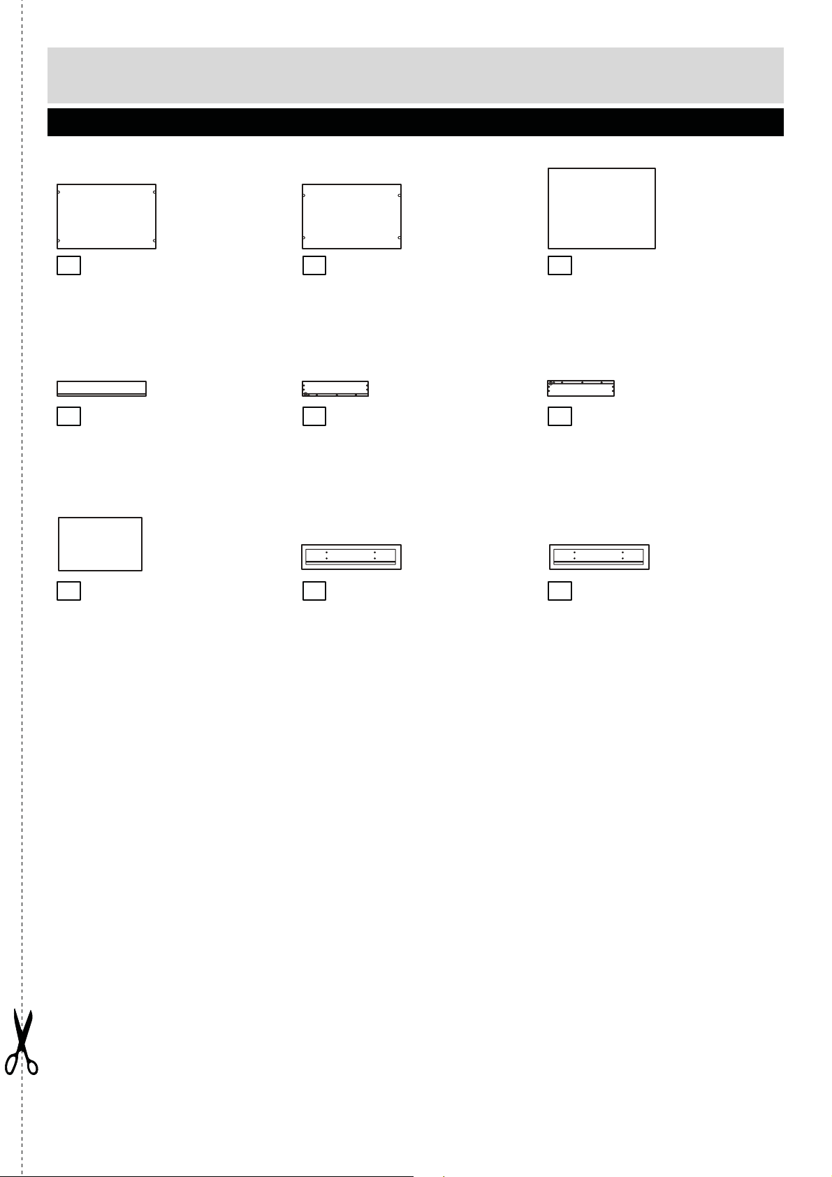
Components - Panels
Please check you have all the pan els listed below
Top right side panel x 1
1
(40 x 15cm)
Top back panel x 1
4
(106.5 x 15cm)
Glass To p x 1
7
(120 x 40cm)
Top left side panel x 1
2
(40 x 15cm)
Top panel x 1
5
(120 x 40cm)
Metal tube x 4
8
(14 x 3.8cm)
Top middle panel x 1
3
(36.8 x 15cm)
Supporting panel x 2
6
(52.5 x 3.5cm)
Metal tube x 4
9
(58 x 3.8cm)
(58 x 34cm)
Bottom panel x 1
(120 x 40cm)
Lower left side panel x 1
(58 x 40cm)
Feet x 5
(3.8 x 3.2cm)
Lower right side panel
121110
(58 x 40cm)
Back Panel x 1
151413
(109 x 60.5cm)
x 1Divider x 1
2
Page 4
Components - Panels
Please check you have all the pan els listed below
Shelf x 1
(52.4 x 34cm)
Drawer back panel x 2
(47.5 x 8cm)
Drawer bottom x 2
(48.5 x 33.5cm)
Shelf x 1
(52.4 x 34cm)
Drawer left side panel x 2
(35 x 8cm)
Left drawer front panel x 1
2322
(53 x 12.7cm)
Glass door x 1
181716
(57 x 52.7cm)
Drawer right side panel x 2
212019
(35 x 8cm)
Right drawer front panel x 1
24
(53 x 12.7cm)
3
Page 5
If you have damaged or missing components,
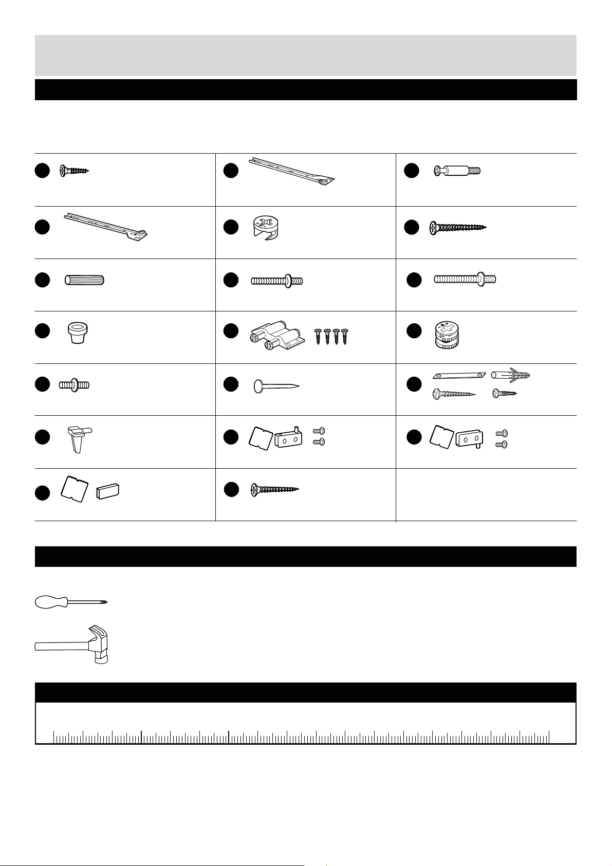
Components - Fittings
call the Customer Helpline: 08456 400800
Please check you have all the fittings listed below
Note: The quantities below are the correct amount to complete the assembly. In some cases more
fittings may be supplied than are required.
A
12mm Screw x 8
D
Left side runner x 2
G
25mm Plastic dowel x 24
Easy door assembly spring x 4
M O
25mm Screw x 1
P
Supporter x 8
B
E
9.5mm Cam x 6
H
32mm Screw x 4 55mm Screw x 8
KJ
Door catch set x 1
N
Nail x 20
Q
Left hinge set x 2
C
37mm cam pillar x 12Right side runner x 2
F
38mm Screw x 18
I
L
12.5mm Cam x 6
Wall mounting strap x 2
R
Right hinge set x 2
S
Counterplate set x 2
T
30mm Screw x 16
Tools required
Crosshead screwdriver
(not included)
Hammer
(not included)
Ruler - Use this ruler to help correctly identify the screws
0 5 10 15 20 25 30 35 40 45 50 55 60 65 70 75 80 85 90 95 100 110 120105 115 125 130 135 140 145 150 155 160 165 170
4
Page 6

Assembly Instructions
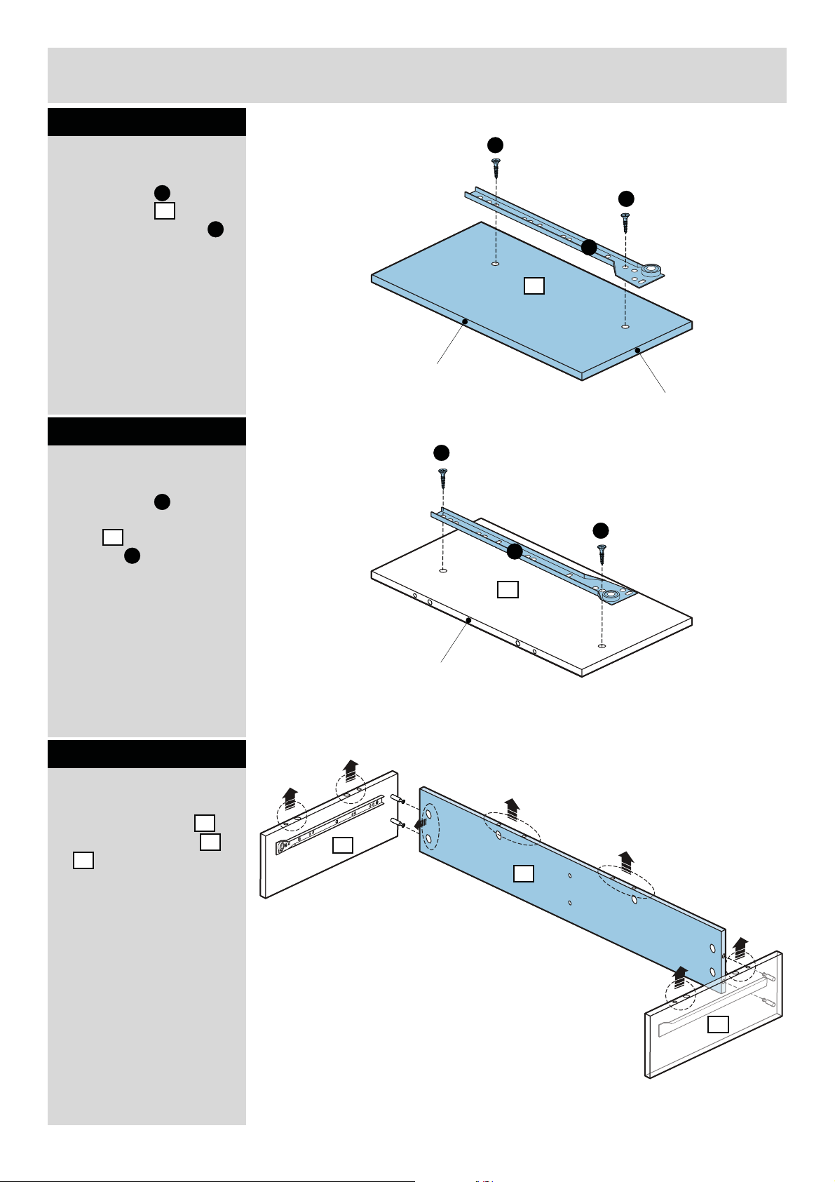
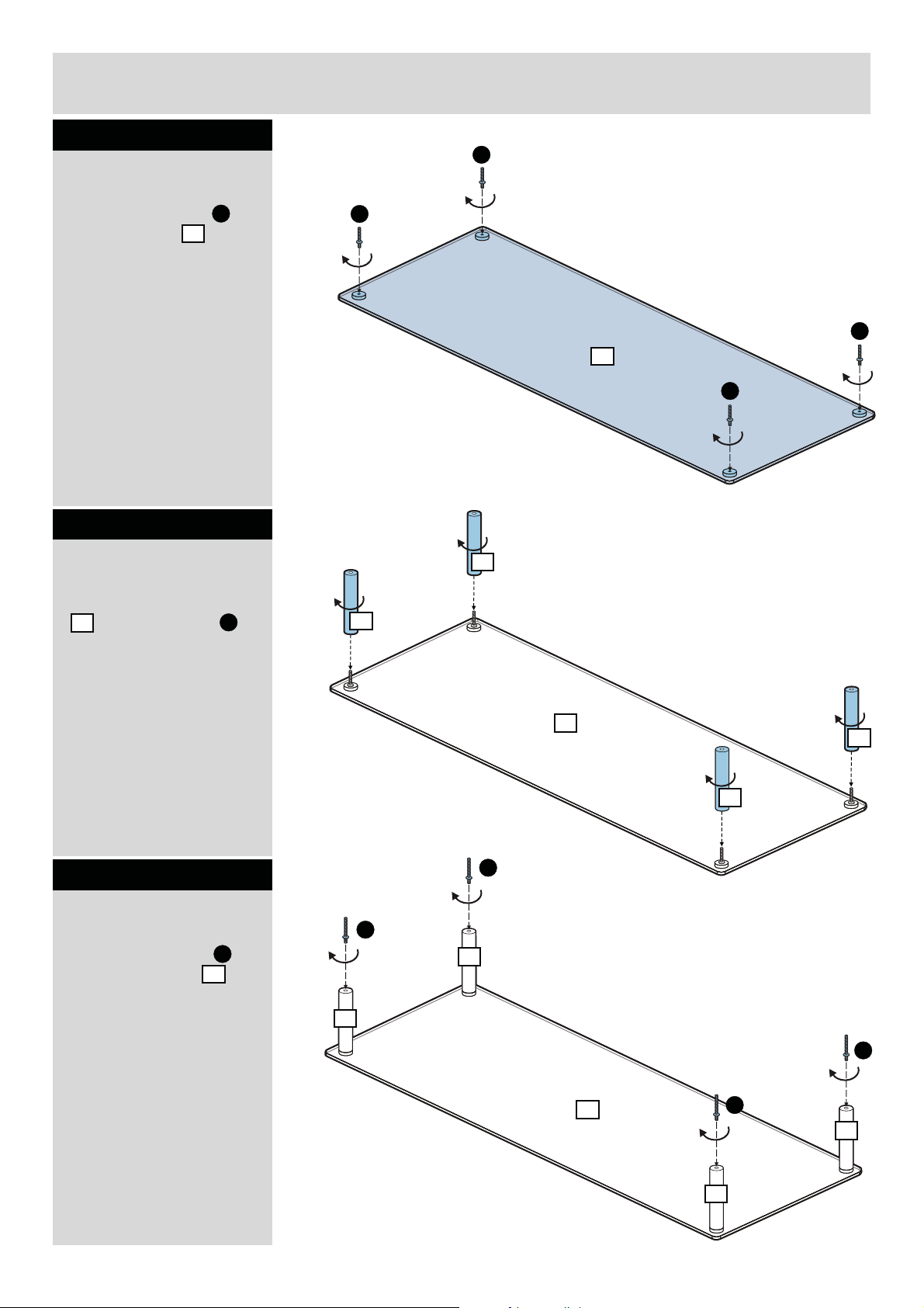
Step 1
Attaching runner
Place runner onto
right side panel by
using 2 pcs of screw .
B
1
A
Note: If panels
have any
transparent
protection film,
remove from ALL
panels before
starting.
Step 2
Attaching cam pillar
Fix 2 pcs of cam pillars
C
onto right side panel
.
1
A
A
B
1
Unfinished edge
C
C
1
Step 3
Attaching runner
Place runner onto left
side panel by using 2
pcs of screw to fix as
D
2
A
shown.
Step 4
Attaching cam pillar
Fix 2 pcs of cam pillars
C
onto left side panel
2
.
A
A
D
2
Finished edge
C
C
2
5
Page 7
Assembly Instructions
Step 5
Attaching runner
A
Place runner onto top
middle panel by
using 2 pcs of screw .
D
3
A
Step 6
Attaching runner
Place runner onto the
other side of top middle
panel by using 2 pcs
3
of screw .
B
A
A
D
3
Finished edge
Finished edge
A
A
B
3
Step 7
Attaching panel
Fix top back panel
between side panel
2
& .
4
1
Unfinished edge
1
4
2
6
Page 8
Assembly Instructions
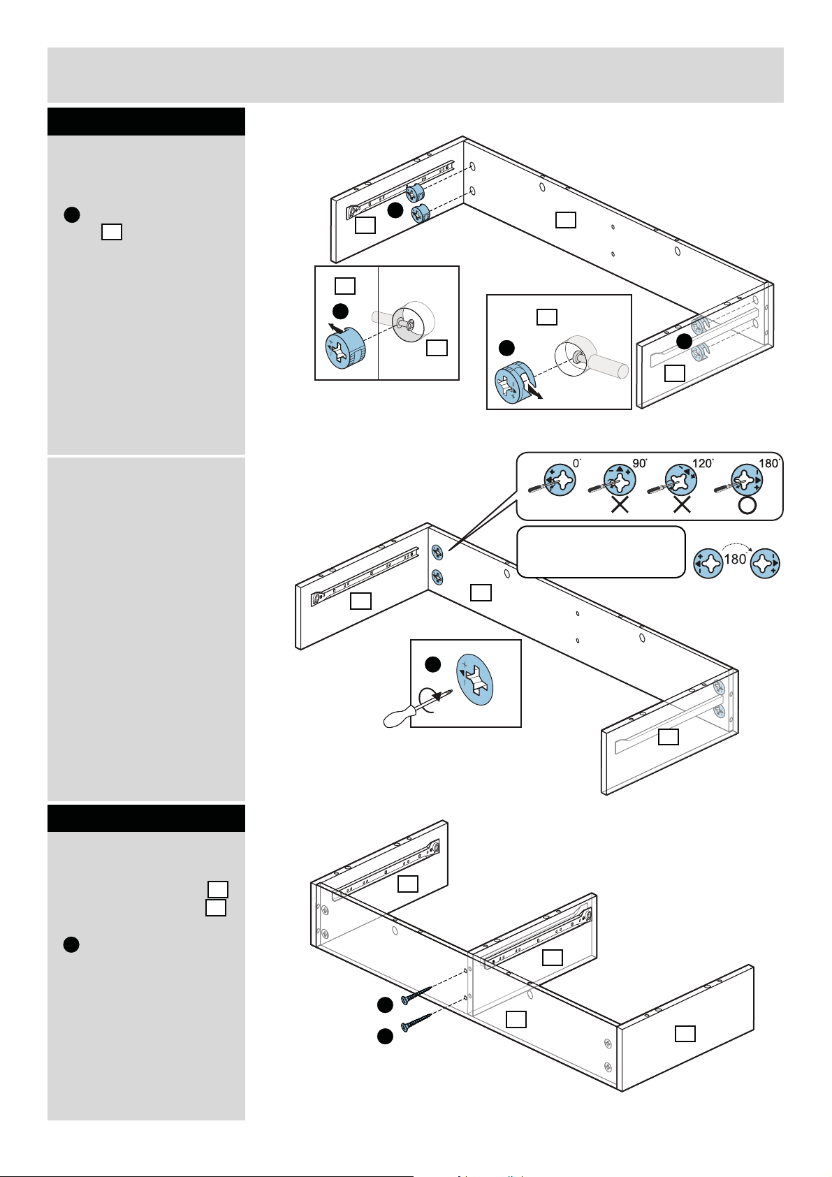
Step 8
Attaching cam
a: Insert 4 pcs of cam
E
onto the top back
panel .
b: adjust the
arrow on cam to the
correct position as
shown.
4
Please
a:
b:
E
1
1
E
4
E
4
4
Caution:
Tur n 180 Degree clockwise
to fasten the cams.
E
2
TURN
Step 9
Attaching panel
Fix top middle panel
onto top back panel
by using 2 pcs of screw
.
F
3
4
1
E
2
4
2
3
F
4
F
1
7
Page 9

Assembly Instructions
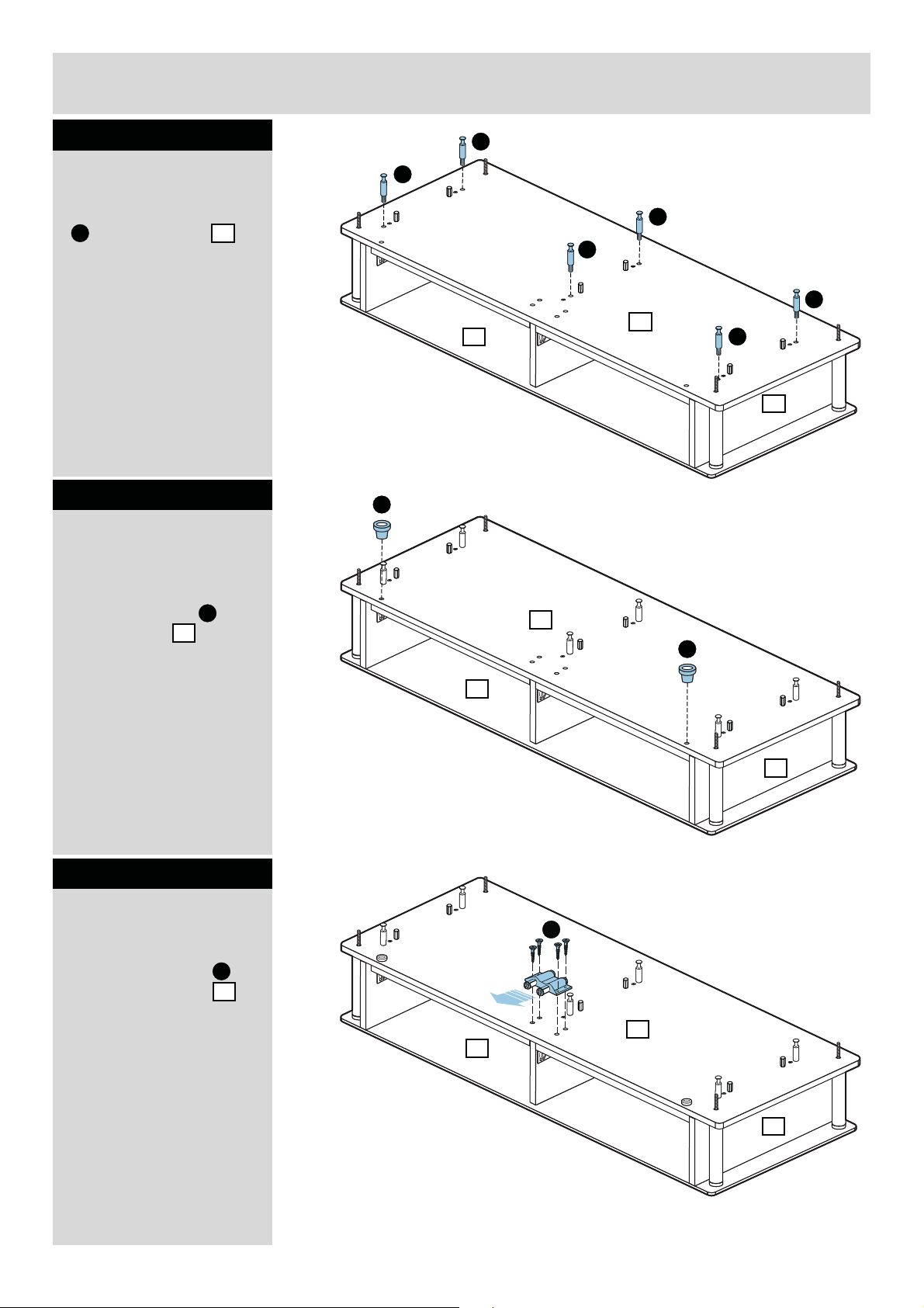
Step 10
Fitting dowels
Insert 12 pcs of plastic
dowels into top panel
.
5
G
Step 11
Attaching cam pillar
Fix 2 pcs of cam pillars
C
onto top panel .
5
G
G
5
G
G
G
G
C
C
Step 12
Attaching panel
Fix 2 pcs of supporting
panel onto top panel
by using 4 pcs of
screw .
6
5
F
5
F
F
F
6
F
6
5
8
Page 10

Assembly Instructions
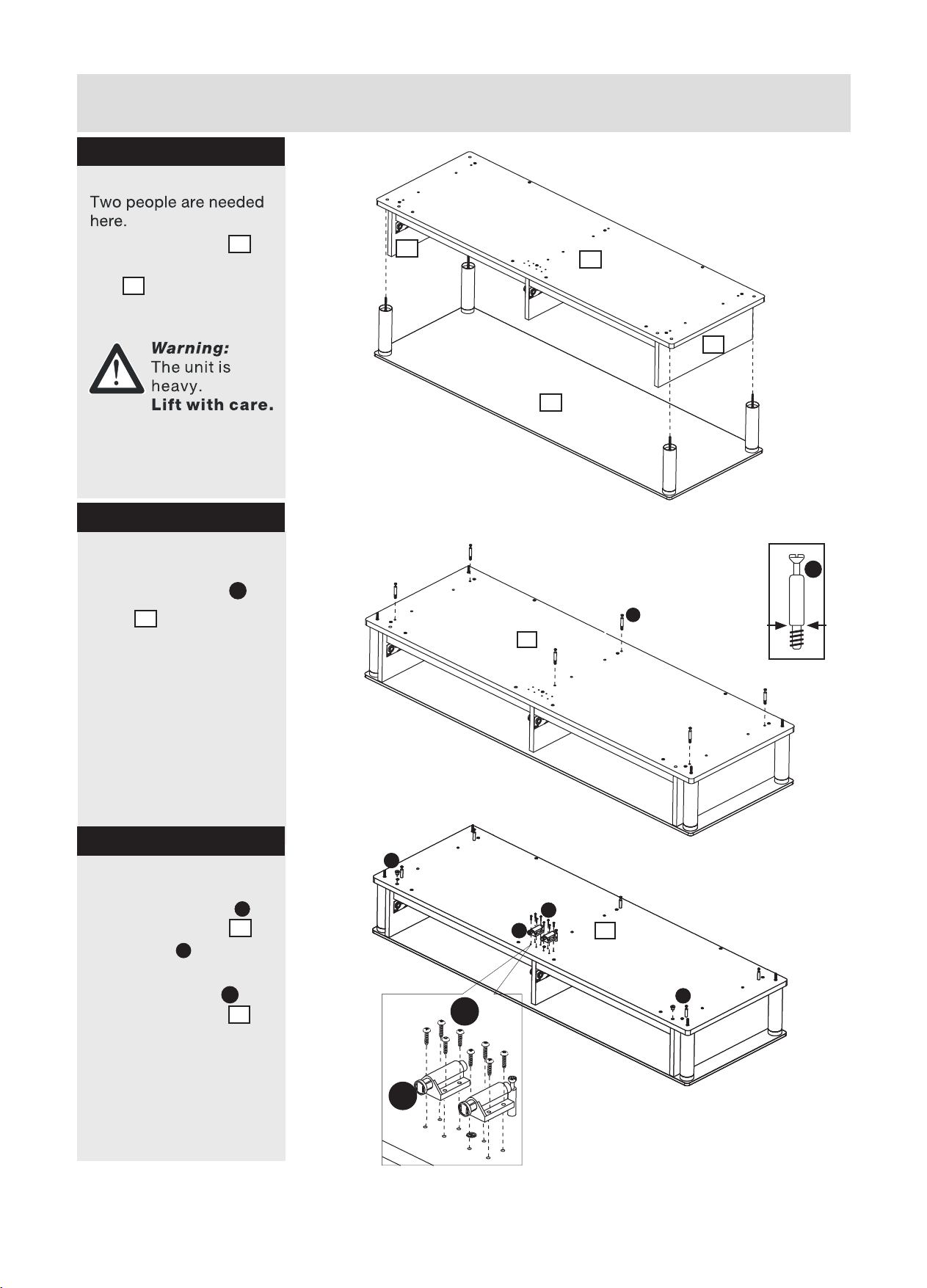
Step 13
Attaching panel
Two people are needed
here.
Fix panel 5 onto panels
1 2 3 4
by using
6 pcs of screw .
F
F
F
Warning:
The unit is
heavy.
Lift with care.
Step 14
a:
Attaching cam
a: Insert 2 pcs of cam
E
onto the top back
panel .
4
2
3
F
5
1
4
F
F
F
E
2
4
5
E
E
4
1
b: adjust the
Please
b:
2
arrow on cam to the
correct position as
shown.
5
TURN
4
4
Caution:
Tur n 180 Degree clockwise
to fasten the cams.
E
1
9
Page 11
Assembly Instructions
Step 15
Attaching screws
H
Fix 4 pcs of screw
onto glass top .
H
7
Step 16
Attaching metal tube
Fix 4 pcs of metal tube
onto the screw .
8
H
H
H
7
H
8
8
Step 17
Attaching screw
Fix 4 pcs of screw
onto metal tubes .
I
8
7
8
I
I
8
8
7
I
8
I
8
8
10
Page 12

Assembly Instructions
Step 18
Attaching panel
Two people are required
here.
Fix the top panel
5
onto the 4 pcs of metal
tube .
8
Warning:
The unit is
heavy.
Lift with care.
1
8
5
8
7
2
8
8
Step 19
Fitting dowels
Insert 6 pcs of plastic
dowel into panel .
G
5
G
G
G
5
7
G
G
G
2
11
Page 13
Assembly Instructions
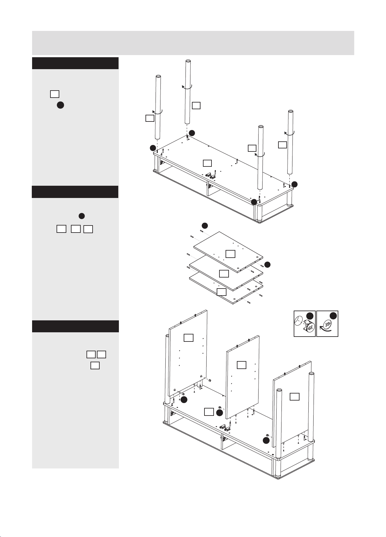
Step 20
Attaching cam pillar
Fix 6 pcs of cam pillars
C
onto top panel .
5
Step 21
Inserting door
assembly spring
C
C
C
C
C
7
5
J
C
2
Insert 2 pcs of door
assembly spring onto
the top panel .
J
5
Step 22
Attaching door catch
set
Fix door catch set
onto the top panel
as shown.
K
5
5
J
7
2
K
5
7
2
12
Page 14

Assembly Instructions
Step 23
Attaching metal tube
Attach 4 pcs of metal
tube onto 4 pcs of
screw .
9
I
9
9
9
I
9
I
5
I
7
I
Step 24
Attaching divider
panel
Attach divider panel
onto panel .
5
2
10
10
2
5
13
1
Page 15

Assembly Instructions
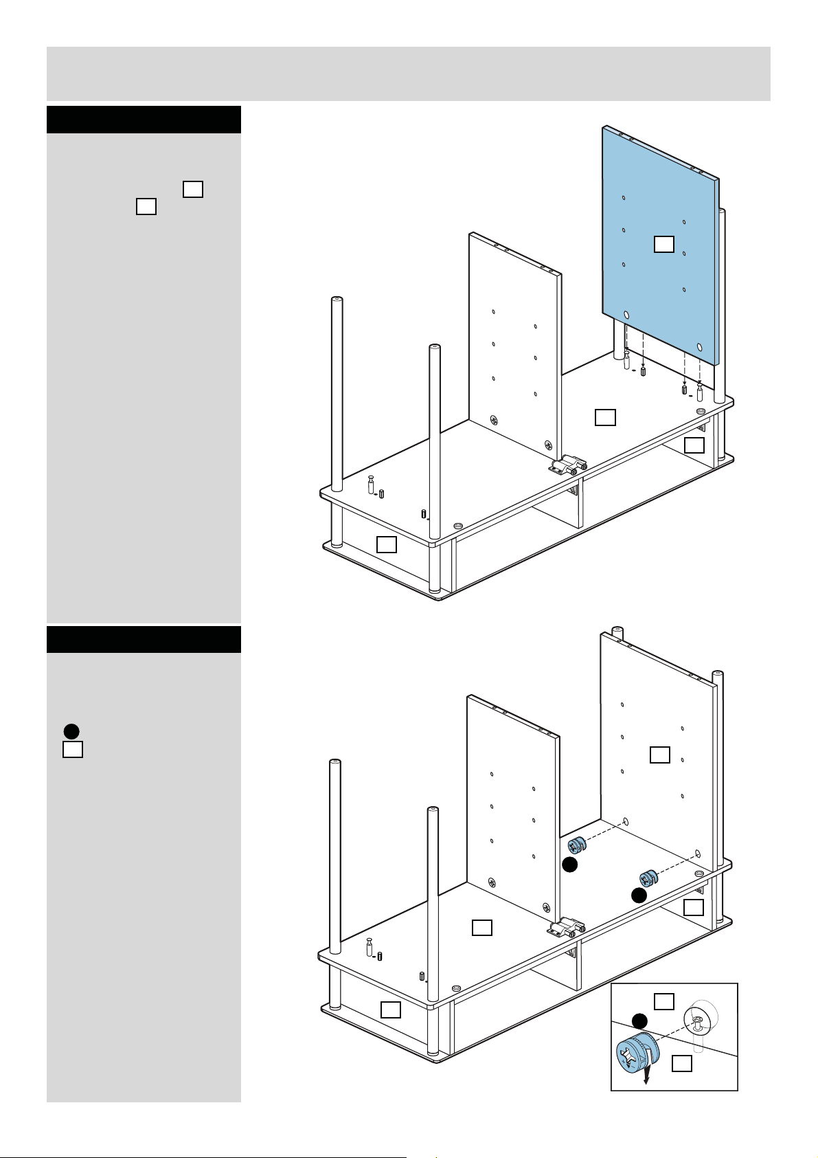
Step 25
a:
Attaching cams
a: Insert 2 pcs of cam
L
onto divider .
10
10
5
L
L
b: Please adjust the
arrow on cam to the
correct position as
shown.
b:
10
1
10
5
L
5
L
1
TURN
Caution:
Tur n 180 Degree clockwise
to fasten the cams.
14
Page 16
Assembly Instructions
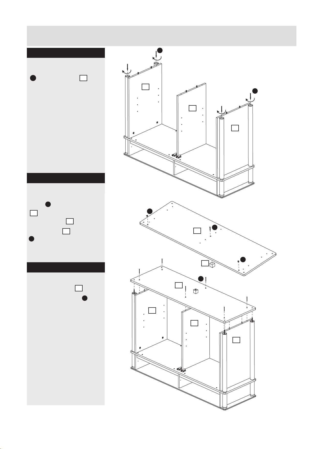
Step 26
Attaching side panel
Attach side panel
onto panel as
5
shown.
11
11
5
2
1
Step 27
Attaching cams
a: Insert 2 pcs of cam
onto the side panel
L
11
.
a:
11
L
L
5
1
L
2
11
Continued on next page.
15
5
Page 17

Assembly Instructions
Step 27 - continued
b: Please adjust the
arrow on cam to the
correct position as
shown.
b:
11
L
2
5
TURN
1
Caution:
Tur n 180 Degree clockwise
to fasten the cams.
Step 28
Attaching side panel
Attach side panel
onto panel as
shown.
5
12
12
11
5
1
2
16
Page 18

Assembly Instructions
Step 29
Attaching cam
a: Insert 2 pcs of cam
L
onto the side panel
12
.
a:
12
L
1
L
5
12
L
11
2
b: Please adjust the
arrow on cam to the
correct position as
shown.
b:
L
TURN
5
12
11
1
5
17
Caution:
Tur n 180 Degree clockwise
to fasten the cams.
2
Page 19

Assembly Instructions
Step 30
Fitting dowels
Insert 6 pcs of plastic
dowel into panel
11
.
G
12
10
G
G
G
G
G
12
10
G
11
Step 31
Insert door assembly
spring
Insert 2 pcs of door
assembly spring onto
the bottom panel .
J
13
J
13
J
Finished side
18
Page 20
Assembly Instructions
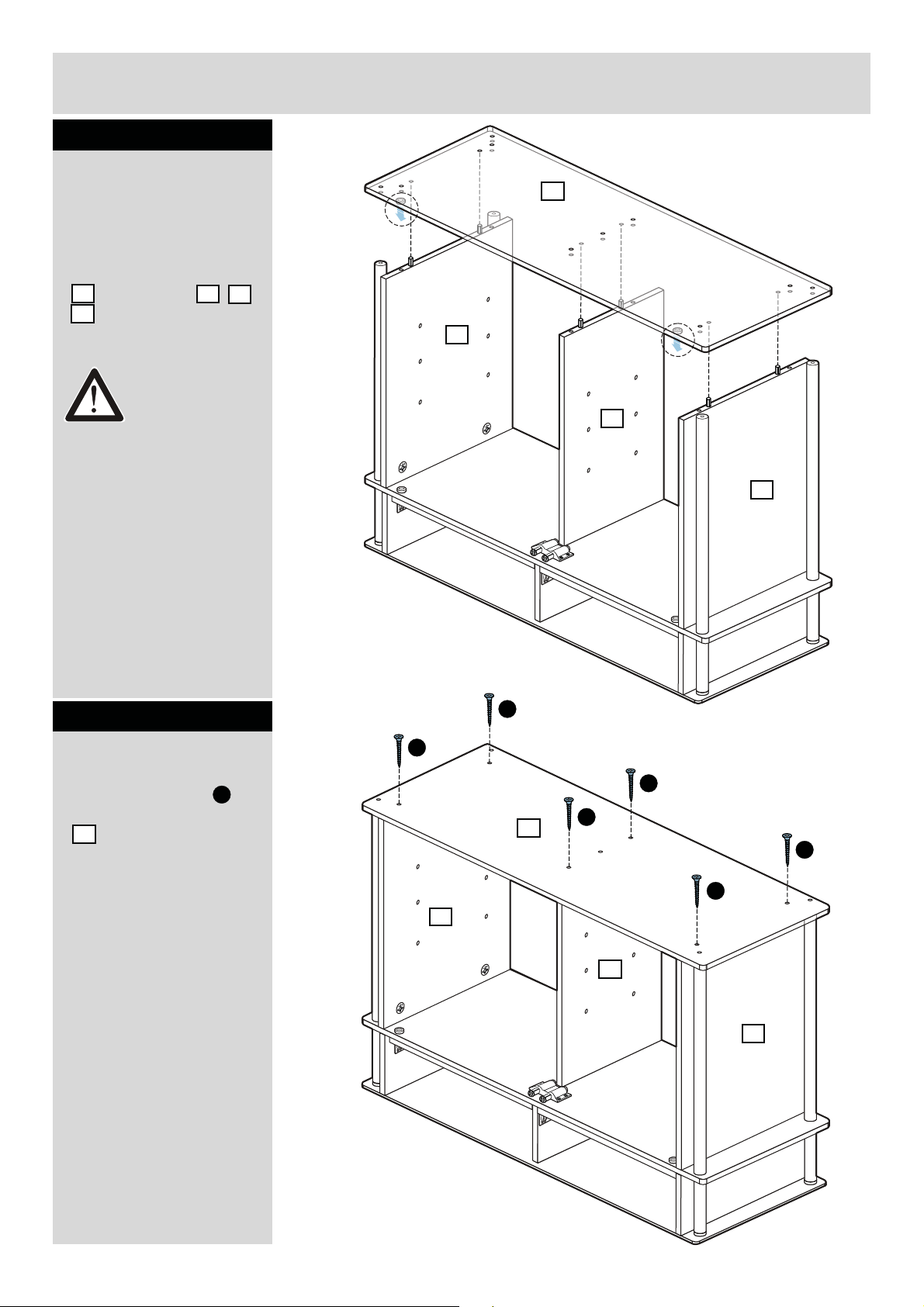
Step 32
Attaching panel
Two people are required
here.
Attach the bottom panel
13
onto panels
12
.
Warning:
The unit is
heavy.
Lift with care.
10
11
13
12
10
11
Step 33
Attaching screws
Fix 6 pcs of screw
onto the bottom panel
13
.
F
F
F
F
13
12
F
F
F
10
11
19
Page 21

Assembly Instructions
Step 34
Attaching screw
Fix 4 pcs of screw
and 1 pc of screw
onto panel as
shown.
13
M
I
I
I
13
9
12
M
13
I
9
9
I
I
9
11
Step 35
Attaching foot
Fix 5 pcs of stand feet
14
onto screws &
on panel .
13
I
M
14
I
14
I
14
13
12
M
14
I
14
I
11
20
Page 22

Assembly Instructions
Step 36
Attaching back panel
Place back panel
15
onto the by using 20 pcs
of nails with hammer
N
as shown.
N
N
N
15
4
N
12
Step 37
Attaching wall
mounting strap
Attach 2 pcs of wall
mounting strap onto
back panel by using
the screws supplied.
Warning:
The unit is heavy.
Turn with care.
O
4
O
4
O
4
O
12
21
Page 23

Assembly Instructions
Step 38
Fitting shelf support
Insert 8 pcs of shelf
12
P
11
10
11
support at the proper
position of panel
and .
13
P
P
10
12
Step 39
Attaching shelf
Place the shelf &
onto the unit.
16 17
16
11
10
17
12
22
Page 24

Assembly Instructions
1
2
3
4
5
1
2
3
4
5
Step 40
Door assembly
Please ensure you are
facing the frosted side
of the glass as
shown.
Incorrect assembly will
result failure on
assembly step 43.
18
18
18
a: Peel off the cover
layer and attach parts
as shown.
Q
b: Peel off the cover
layer and attach parts
as shown.
R
Step 41
a:
Frosted side
Q
a:
52. cm7
18
10
b:
Frosted side
Unfrosted side
57cm
R
b:
Attaching door hinge
Please make sure the
parts as shown is the
correct one for
assembly at this stage.
CAUTION:
Before tighten the glass
with the parts ,
please ensure the parts
align to the
the glass door.
23
Q
Q
Q
edge of
Q
Q
18
18
Frosted side
Page 25

Assembly Instructions
Step 42
Attaching door hinge
Attach parts onto the
bottom panel .
R
13
11
R
13
12
Step 43
Attaching door
Two people are required
here.
a: Insert part
underneath panel .
b: Slide glass door into
parts onto bottom
panel .
R
13
Q
5
Frosted side
18
5
a:
b:
Q
11
13
R
12
24
Page 26

Assembly Instructions
1
2
3
4
5
1
2
3
4
5
Step 44
Attaching door
Two people are required
here.
Before tighten the glass
with parts , please
ensure the parts align
to the glass door .
R
R
18
18
Step 45
Door assembly
Please ensure you are
facing the frosted side
of the glass as
shown.
18
a:
R
18
13
R
13
R
a:
52. cm7
12
a: Peel off the cover
layer and attach parts
as shown.
R
57cm
18
b: Peel off the cover
layer and attach parts
as shown.
25
Q
Q
b:
Unfrosted side
b:
Page 27

Assembly Instructions
Step 46
Attaching door hinge
Please make sure the
parts as shown is the
R
correct one for
assembly at this stage.
CAUTION:
Before tighten the glass
with the parts ,
R
please ensure the parts
R
align to the edge
of
the glass door.
Step 47
Attaching door hinge
Attach parts onto the
bottom panel .
Q
13
R
R
18
18
Unfrosted side
Step 48
Attaching door
Two people are required
here.
a: Insert part
underneath panel .
b: Slide glass door into
parts onto bottom
panel .
Q
13
R
5
18
Frosted side
18
13
18
a:
12
Q
5
R
12
13
Unfrosted side
b:
Q
26
Page 28

Assembly Instructions
1
2
3
4
5
Step 49
Attaching door
Two people are required
here.
Before tighten the glass
with parts , please
ensure the parts align
to the glass door .
Q
Q
18
Step 50
Attaching
counterplate set
Remove the underlying
layer of the sticker
and attach to the glass
door at the position as
shown.
S
18
13
18
Q
S
12
18
S
12
18
Frosted side
Unfrosted side
27
Page 29

Assembly Instructions
Step 51
Attaching drawer
panels
Attach drawer side
panel to drawer back
panel by using 2 pcs
of screw
Attaching drawer
panels
Attach drawer side
panel to drawer back
panel by using 2 pcs
of screw .
20
19
.
Step 52
21
19
T
T
T
T
19
20
T
T
21
Step 53
Attaching drawer
panels
Slide drawer bottom
panel into the
drawer unit as shown.
22
19
20
Finished side
22
21
20
19
28
Page 30

Assembly Instructions
Step 54
Attaching drawer
front panel
Attach drawer front
panel onto the
drawer unit.
23
23
21
22
20
19
Step 55
Fixing drawer front
panel
a: Fixing drawer front
panel by using 4 pcs of
screw .
b: Repeat step 51 to
step 55 for right hand
side drawer as shown.
T
a:
b:
T
T
23
21
T
T
20
T
T
29
24
21
T
T
20
Page 31

Assembly Instructions
Step 56
Fixing drawers
Slide 2 x drawers into
the unit as shown.
23
24
12
Step 57
Prepare wall mount
strap
Pull the wall mount strap
O
upward as shown.
O
7
12
O
30
Page 32

Assembly Instructions
Step 58
Fixing to wall
It is recommended that
the unit is fixed to a wall
for safety concern.
Please ensure the wall
strap fix on top of the
O
unit by using screws.
With help, move the unit
into position.
Warning:
The unit is
heavy.
Lift with care.
Marking the fixing holes
position on wall and then
remove the unit.
Drill 6mm hole and insert
wall plug.
Note: Wall plug supplied are
for solid wall only.
The correct type of fixing
must be used for your wall,
seek professional advice if in
wall
O
doubt.
MIN
23.mm5
BRICK
22.mm5
Ø
6
mm
Warning:
Before drilling,
check wall for
hidden pipes
and cables.
Reposition the unit and
fix wall strap to the wall
plug by using screws.
If you need help or have damaged or missing parts, call the Customer Helpline: 08456 400800
31
Page 33

Page 34

Matrix Large Sideboard
Assembly Instructions - Please keep for future reference 6142151
haygena
Dimensions
Width - 120cm
Depth - 40cm
Height - 80cm
Important - Please read these instructions fully before starting assembly
If you need help or have damaged or missing parts, call the Customer Helpline : 08456 400800
issue 1 04/02/10
Page 35

Safety and Care Advice
Important - Please read these instructions fully before starting assembly
Check you have all the
components and tools listed on
pages 2 and 3.
Remove all fittings from the
plastic bags and separate them
into their groups.
Keep children and animals
away from the work area, small
parts could choke if swallowed.
Make sure you have enough
space to layout the parts before
starting.
Care and maintenance
Only clean using a damp cloth
and mild detergent, do no use
bleach or abrasive cleaners.
Do not stand on the panels, this
could cause damage.
Assemble the unit as close to its
final position (in the same room)
as possible.
Assemble on a soft level
surface to avoid damaging the unit
or your floor.
Parts of the assembly will be
easier with 2 people.
From time to time check that
there are no loose screws on this
unit.
We do not
recommend the use
of power drill/ drivers
for inserting screws,
as this could damage
the unit. Only use hand
screwdrivers.
Dispose of all packaging carefully
and responsibly.
Warning: The unit weighs
approximately 53.5kgs.
Please lift with care.
This product should not be
discarded with household waste.
Take to your local authority waste
disposal centre.
Note: If required the next page
can be cut out and used as a
reference throughout the
assembly. Keep this page with
these instructions for future
reference.
1
Page 36

Components - Panels
If you have damaged or missing components,
call the Customer Helpline : 08456 400800
Please check you have all the panels listed below
1
Top right side panel
(39.9 x 15.1 cm)
4
Glass Top (120 x 40cm)
6
Bottom panel (120 x 40cm)
2
Top left side panel
(39.9 x 15.1cm)
3
Top middle panel
(36.7 x 15.1cm)
5
Top panel (120 x 40cm)
7
Top back panel (106.5 x 15.1cm)
8
Lower right side panel
(58 x 39.9cm)
11
Back panel (109.4 x 61cm)
9
Lower left side panel
(58 x 39.9cm)
12
Supporting panel x 2
(52.4 x 3.5cm)
13
Shelf x 2
(52.5 x 33.9cm)
10
Lower middle panel
(58 x 34cm)
14
Metal tube x 4
(58 x 3.8cm)
15
Metal tube x 4
(14 x 3.8cm)
16
Metal tube x 4
(3.2 x 3.8cm)
2
Page 37

Components - Panels
If you have damaged or missing components,
call the Customer Helpline : 08456 400800
Please check you have all the panels listed below
17
Left drawer front panel
(52.8 x 13cm)
19
Left drawer side panel x 2
(34 x 8cm)
Drawer back panel x 2
21
(47.6 x 8cm)
18
Right drawer front panel
(52.8 x 13cm)
20
Right drawer side panel x 2
(34 x 8cm)
Drawer bottom x 2
22
(48.6 x 33.8cm)
Glass door x 2
23
(57.2 x 52.8cm)
3
Foot
24
(3.2 x 3cm)
Page 38

Components - Fittings
Please check you have all the fittings listed below
Note: The quantities below are the correct amount to complete the assembly. In some cases more fittings
may be supplied than are required.
A
Locking Pin x 18
D E F
Dowel 30mm x 24 38mm Screw x 9
G
15mm Screw x 32
J
Right drawer runner x 2
M
45mm Screw x 20
P
15mm Screw x 2
S
B
15mm Locking nut x 10
12mm Screw x 8
H
Left drawer runner x 2
K
Right side runner x 2
N
Wall plug x 2
Q
25mm Screw x 2
T
C
12mm Locking nut x 8
I
Left side runner x 2
L
Shelf support x 8
O
Wall strap x 2
R
Right hinge set x 2
U
Left hinge set x 2
V
S
Door catch set screw x 8
Y
S
Pad x 2
Counterplate x 2
W
S
Ease door assembly spring x 4
Tools required
Phillips screwdriver
(medium & large)
Flatblade screwdriver
(medium)
7mm Masonary drill bit
(for use with wall plug)
Small
hammer
Drill
(Drill holes
for wall plug)
Ruler - Use this ruler to help correctly identify the screws
Door catch set x 2
X
S
55mm Screw x 12
Eye protection
(when using a
hammer or glue)
Ruler/tape
measure
0 5 10 15 20 25 30 35 40 45 50 55 60 65 70 75 80 85 90 95 100
105
110 115 120 125 130 135 140 145 150 155 160 165 170
4
Page 39

Assembly Instructions
Step 1
Step 1
Attaching runner
Fix runner onto
Top left side panel
I
2
by using 3 pcs of
Screw .
G
Step 2
Attaching Locking pin
Fix 2 pcs of Locking pin
A
and Dowel into
Top left side panel
D
2
.
G
I
A
G
I
2
D
A
Step 3
Step 3
Attaching runner
Fix runner onto
Top right side panel
Top right side panel
by using 3 pcs of
by using 3 pcs of
Screw to fix as shown.
K
1
1
G
Step 4
Attaching Locking pin
Fix 2 pcs of Locking pin
A
and Dowel into Top
right side panel
D
1
.
G
K
A
D
G
K
1
5
Page 40

Assembly Instructions
Assembly Instructions
Step 5
Attaching runner
Fix runner onto
Top middle panel
b y using 3 pcs
of Screw .
K
3
G
Step 5Step 6
Attaching runner
Fix runner onto
Top middle panel
by using 3 pcs of Screw
E
G
. Insert Dowel into
Top middle panel .
I
3
D
3
Step 5Step 7
Stick Pad
G
K
Y
G
K
3
G
I
D
Fix Stick Pad onto
Top middle panel .
Y
3
Step 5Step 8
Attaching panel
Fix Top back panel
with side panel
Insert Dowel into Top
back panel .
1
&
.
D
7
G
I
B
2
B
1
B
D
7
B
2
6
Page 41

Assembly Instructions
Assembly Instructions
Step 3
Step 9
Attaching panel
Fitting sides & middle
Fix Top middle panel
onto the unit by using
3
2 pcs of Screw .
Step 3
Step 10
M
Attaching panel
1
7
3
M
2
Fix top onto panels
1
8 pcs of Screw .
Step 3
Step 11
5
3 7
b y using
M
2
Attaching panel
Insert 2 pcs of dowel
onto the Supporting
.
12
Fix Supporting panel
onto the unit with
F
.
Screw
D
panel
12
M
5
1
3
2
D
12
5
F
12
12
7
Page 42

Assembly Instructions
Assembly Instructions
Step 4
Step 12
Attaching Screws
Fitting top & back
Fix 4 pcs of Screw
onto glass top .
X
4
X
c into Top .A
Step 4
Step 13
1
Attaching Metal tube
Fix 4 pcs of metal tube
15
onto the Screw .
X
15
4
4
4
4
4
Step 4
Step 14
Attaching Screw
Fix 4 pcs of screw
onto glass top .
4
X
X
c:
15
4
4
4
8
Page 43
Assembly Instructions
Assembly Instructions
Step 15
Attaching panel
Fix the top panel
5
o nto the 4 pcs of metal
15
tube .
Step 16
Attaching locking pin
Insert Locking pin into
panel .
5
A
4
1
4
5
4
5
4
2
4
4
A
A
D
Step 17
Attaching door catch
set
Fix door catch set
onto the Top panel
with Screw as shown.
V
Insert 2 pcs of Door
assembly spring
onto the Top panel .
9
5
W
5
W
W
UU
V
V
U
U
4
4
5
5
W
W
V
U
Page 44
Assembly Instructions
Assembly Instructions
Step 18
Attaching Metal tube
Fix attach 4 pcs of metal
14
tube onto 4 pcs of
Screw .
X
4
14
X
Step 19
Attaching Dowel
Insert Dowel into
4
panel .
8
D
4
9
10
4
4
14
X
4
4
14
4
5
X
D
14
X
Step 20
Attaching side panel
Attaching side panel
Fix side panel
and middle panel .
and middle panel .
8 9
8 9
10
10
10
4
D
4
9
4
8
B
4
8
10
4
4
B
4
5
B
9
B
B
10
Page 45
Assembly Instructions
Assembly Instructions
Step 21
Attaching Screws
Fix 4 pcs of screw
X
o nto metal tubes .
14
Step 22
Attaching Panel
Fix Insert Door assembly
s pring onto Bottom panel
Attaching Foot onto
Bottom panel with Screw
F
4
6
.
.
WW
4
24
4
6
X
4
4
8
10
4
4
9
W
W
4
6
F
X
Step 23
Attaching Panel
Fix Bottom panel
the unit with Screw
onto
4
24
M
4
4
6
M
.
4
8
6
10
4
W
4
9
11
Page 46

Assembly Instructions
Assembly Instructions
Step 24
Attaching Metal tube
Attaching Metal tube
Screwing Meta tube
4
4
16
16
onto panel
4
4
6 .
6 .
16
4
4
6
Step 25
Attaching back panel
Fix back panel
this unit by using
Screw .
G
onto
11
20 pcs
11
4
G
12
Page 47

Assembly Instructions
Assembly Instructions
Step 26
Attaching wall
Attaching
mounting strap
Fix Wall strap onto
Top back panel by
using the Screw .
O
7
P
Step 27
Attaching shelf
Insert 8 pcs of shelf
support at the proper
position of panel
L
8 9 10
P
O
7
O
P
Place the shelf onto
the unit.
13
13
9
L
10
L
13
L
8
L
13
Page 48

Assembly Instructions
Assembly Instructions
Step 28
Attaching door hinge
Make sure the
S
R
p arts as shown is
the correct one for
assembly at this stage.
CAUTION:
Before tighten the glass
S
with the parts ,
Please ensure the parts,
align to the edge of
the glass door .
R
23
23
R
S
R
S
Step 29
Attaching door
Two people are required
h ere.
a:Attach glass door
onto the unit.
b:Fix by tools as shown.
23
23
23
23
a:
b:
5
23
14
Page 49

Assembly Instructions
Assembly Instructions
Step 30
Attaching door
Attaching
Two people are required
h ere.
a:Before tighten the
glassl with parts
alight to the glass door .
S
23
23
a:
5
23
S
a:
23
23
b:
Step 31
Door assembly
Two people are required
h ere.
b:Make ensure you are
facing the frosted side
of the glass door as
shown.
Peel off the cover layer
and attach parts as
shown.
23
23
T
b:
T
23
23
T
b:
15
Page 50

Assembly Instructions
Step 32
Fitting drawers
a: Use Screws to fix
Left drawer runner
onto the Drawer left .
b: Use Screws to fix
Right drawer runner
onto the Drawer right .
c: Use Screws to fix
Drawer left Drawer
right onto Drawer
20
back .
21
E
H
19
E
J
20
F
19
c:
b:
E
H
a:
H20H
E
19
J
J
F
19
E
E
21
d: Screwing Locking pins
c into Drawer front .
A
18
17
e: Slide Drawer bottom
c into the unit.
17
Use Locking nuts to
fix Drawer front onto
the unit.
Use Screws to fix
Drawer knob onto the
unit.
C
23
G
U
e:
A
20
F
d:
A
A
18
17
A
18
C
A
C
C
C
17
23
C
23
C
16
Page 51

Assembly Instructions
Step 33
Fitting drawers
18
Sliding 2 drawers
into the unit as shown.
17
17
18
17
Page 52

Assembly InstructionsAssembly Instructions
Step 9
Fixing to wall
Note: It would be useful to
ask someone to help you
at this stage.
It is strongly recommended
that the unit is attached to
the wall using Wall strap
Q
C .
a:
Important: When drilling
into walls always check
that there are no hidden
wires or pipes etc. Make
sure that the screws and
wall plugs supplied are
suitable for supporting
the unit. Consult a
qualified tradesperson if
you are not sure.
a: With help, place the
unit in the intend position.
b: Drill a hole in the wall
at an appropriate position
and insert Wall plug
(Masonry walls only).
To secure the unit, fix
Wall strap to the wall
using Screw (Masonry
walls only).
Assembly is complete.
O
Q
N
b:
Q
O
N
If you need help or have damaged or missing parts, call the
Customer Helpline : 08456 400800
18
Page 53

 Loading...