

Page 1

Gold
Gold
Gold
Gold Magnetic
Assembly
Assembly
Assembly
Assembly &
Magnetic
Magnetic
Magnetic Bike
&
User
&
& User
Instruction
User
Instruction
User Instruction
Instruction –
–
Please
–
Please
– Please
Please keep
Bike
Bike
Bike
keep
keep
keep for
for
future
for
future
for future
future reference
reference
reference
reference
901
901
901
901 /
/
7609
/
7609
/ 7609
7609
Important
Important
Important
Important –
These Instructions contain important information which will help you get best from your
equipment and ensure safe and correct assembly, use and maintenance.
If you need help or have damaged or missing parts, call the Customer
–
Please
–
Please
– Please
Please read
read
these
read
these
read these
these instructions
instructions
instructions
instructions fully
fully
fully
fully before
before
before
before assembly
1
assembly
assembly
assembly or
Customer
Customer
Customer Helpline
or
using
or
using
or using
using
Helpline
Helpline
Helpline : 0845
0845
0845
0845 600
600
0464
600
0464
600 0464
0464
Page 2

Contents
Contents
Contents
Contents
Safety
Safety
Safety
Safety Information
Components
Components
Components
Components -
Components
Components
Components
Components –
Assembly
Assembly
Assembly
Assembly Instruction
Computer
Computer
Computer
Computer Operation
Exercising
Exercising
Exercising
Exercising Information
Information
Information
Information 3
-
Parts
-
Parts
- Parts
Parts 4
–
Fixing
–
Fixing
– Fixing
Fixing 5
Instruction
Instruction
Instruction 6
Operation
Operation
Operation 12--
Information
Information
Information 22
*
Before
*
Before
*
* Before
Before Starting
*
Muscle
*
Muscle
*
* Muscle
Muscle Chart
Starting
Starting
Starting to
Chart
Chart
Chart 24
to
to
to exercise
exercise
exercise
exercise 22
6
6
6 -
12--
12--
12-- 21
22
22
22 --
-
-
- 11
--
--
-- 23
3
3
3
4
4
4
5
5
5
11
11
11
21
21
21
22
22
22
23
23
23
24
24
24
*
Warming
*
Warming
*
* Warming
Warming up
Care
and
Care
and
Care
Care and
and Maintenance
Exploded
Exploded
Exploded
Exploded Parts
Exploded
Exploded
Exploded
Exploded Parts
Guarantee
Guarantee
Guarantee
Guarantee 3
up
and
up
up and
Maintenance
Maintenance
Maintenance 27
Parts
Parts
Parts Diagram
Parts
Parts
Parts List
Cooling
and
Cooling
and Cooling
Cooling down
Diagram
Diagram
Diagram 28
List
List
List 29--30
down
down
down 25
25
25
25 --
29--30
29--30
29--30
--
--
-- 26
26
26
26
27
27
27
28
28
28
3
1
3
1
3 1
1
2
Page 3

Safety
Safety
Safety
Safety Information
Information
Information
Information
Important
Important
Important
Important –
T
o reduce the risk of serious injury, read the entire manual before you assemble or operate the Roger Black
Gold Magnetic Bike. In particular, note the following safety precautions:
Assembly
Assembly
Assembly
Assembly
• Check you have all the components and tools
listed on pages 4 and 5 , bearing in mind that, for
ease of assembly, some components are
pre-assembled.
• Keep children and animals away from the work
area, small parts could choke if swallowed.
• Make sure you have enough space to layout the
parts before starting.
• Assemble the item as close to its final position
(in the same room) as possible.
• Position the equipment on a clear, level surface.
• Dispose of all packaging carefully and responsibly.
Using
Using
Using
Using
• It is the responsibility of the owner to ensure that
all users of this product are properly informed as to
how to use this product safely.
• This product is intended for domestic use only.
Do
not
Do
not
Do
Do not
not use in any commercial, rental, or institutional
setting.
• Before using the equipment to exercise, always do
stretching exercises to properly warm up.
• If the user experiences dizziness, nausea, chest
pain, or other abnormal symptoms stop
workout
workout
workout
workout and
• Only one person at a time should use the
equipment.
–
Please
–
Please
– Please
Please read
and
seek
and
seek
and seek
seek immediate
read
fully
read
read fully
immediate
immediate
immediate medical
before
fully
before
fully before
before using
medical
medical
medical attention.
using
using
using and
stop
stop
stop the
attention.
attention.
attention.
and
assembly
and
assembly
and assembly
assembly
• Keep hands away from all moving parts.
• Always wear appropriate workout clothing when
exercising. Do
since it may get caught in the equipment. W ear
athletic shoes to protect your feet while exercising.
• Do
equipment.
• Disabled persons should not use the equipment
without a qualified person or doctor in attendance.
• This product is suitable for use r’s weight of:
• This e quipment is not suitable for therapeutic
purposes .
• Breaking system: 16 level auto programme tension
adjustment. R efer following Computer operation
section.
• This product conforms to: (BS EN957)
-PA R TS 1. 5 class (H) - Home Use - Class (C).
• This exercise product has been designed and
manufactured to comply with the latest (BS EN 957)
British and European Safety Standards.
•
instruction book carefully.
the
the
the
• This charger is for indoor use only, do not
expose to rain or water.
• If the supplier cord is damaged, it must be
replaced by manufacturer, it ’ s service agent
or similarly qualified persons in order to avoid
a ha zard.
Do
not
Do
not
Do not
not wear loose or baggy clothing,
Do
not
Do
not
Do not
not place any sharp objects around the
Warning
Warning
Warning
Warning for
Before using the charger, read the
for
the
for
the
for the
the Charger
Charger
Charger
Charger
1
25kgs.
1
25kgs.
1
1
25kgs.
25kgs.
W
arning:
W
arning:
W
W arning:
arning:
important for persons over the age of 35 or persons with pre-existing health problems.You
MUST read all instructions before using any fitness equipment. Argos and its associates assumes no
responsibility for personal injury or property damage sustained by or through the use of this product.
Before beginning any exercise program, consult your Doctor. This is especially
3
Page 4

If you have any damaged or missing parts, Please
Components-parts
Components-parts
Components-parts
Components-parts
:
Please
Please
Please
Please check
Note:
Note:
Note:
Note:
before contacting Argos regarding any missing components.
check
check
check you
Some of the smaller components may be pre-fitted to larger components. Please check carefully
you
have
you
have
you have
have all
all
parts
all
parts
all parts
parts list
list
list
list below
Call the Customer Helpline: 0845
below
below
below
0845
6000
0845
6000
0845 6000
6000 464
464
464
464
5 .
Handl×1
12.
Computer×1
10.
Front Poster×1
37.
Main Frame ×1
13. 9.
Saddle×1 Handle Cover×1
15.
Saddle Poster×1
35.
M16 Lock Knob×1
20.
Front Stabilizer×1
46.
Rear Stabilizer×1
52L&R.
Pedal×1 set
4
72.
Power Charge×1
Page 5

Components
Components
Components
Components –
–
Fixings
–
Fixings
– Fixings
Fixings
Please
Please
Please
Please check
:
NOTE
NOTE
NOTE
NOTE
Φ 25× Φ 9×R30 Arc Washer× 6
check
check
check you
:
:
:
:
Som e o f th e f ixing s ar e pre- f itte d t o th e large r components . Pleas e chec k carefull y befor e
contactin g Argo s regardin g an y missin g fixings 。
7.
7.
7.
7.
Φ 8MM Spring Washer × 6
16.
16.
16.
16.
you
you
you have
have
have
have all
all
fixings
all
fixings
all fixings
fixings listed
listed
listed
listed below
22.
22.
22.
22.
Φ 10MM Spring Washer × 4
17.
17.
17.
17.
M8*1 6 mm Allen Bolt×6
below
below
below
21.
21.
21.
21.
Φ 11× Φ 30×R34 Arc Washer×4
Multi Wrench ×1
5# Allen Wrench×1
71.
71.
71.
71.
Wire Clip × 2
6# Allen Wrench×1
23.
23.
23.
23.
M10* 20 mm Allen Bolt× 4
5
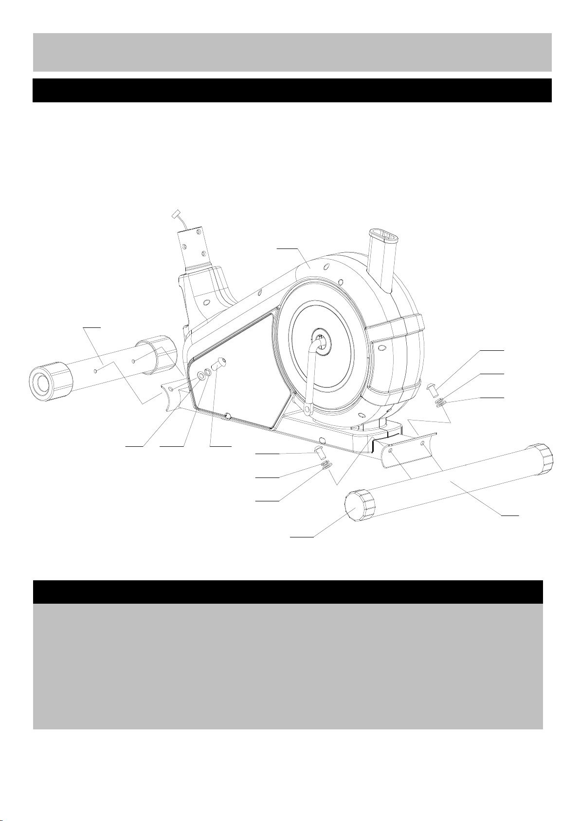
Page 6
A
ss
A
ss
A
A ss
ss embly
embly
embly
embly Instruction
Instruction
Instruction
Instruction
Recommend
Recommend
Recommend
Recommend the
:
NOTE:
NOTE:
NOTE:
NOTE:
Tool
20
a
a
a
a
the
assembly
the
assembly
the assembly
assembly if
required assembly the machine : two adjustable wrenches, and one P hilips screw driver
if
this
if
if this
equipment
this
equipment
this equipment
equipment is
is
carried
is
carried
is carried
carried by
by
two
by
two
by two
two person
person
person
person
1
23
22
21 22 23
Step
1
Step
1
Step
Step 1
1
a.
a.
a.
a. Attach Front stabilizer (20)
using two M10 x20mm Allen bolts (23),
22)
Spring washer s ( 22)
(21).
washers (21).
(21).
(21).
22)
22) ,
(20)
(20)
(20) to Main body (1)
,
,
, Ø
11
x Ø 30 x R34mm Arc adjust the level of the machine.
(23),
(23),
(23), Ø 10mm Slightly turn round the two Level feet (47)
23
22
21
(1)
(1)
(1) c.
47
c.
c.
c. Leverage
Leverage
Leverage
Leverage the
the
machine
the
machine
the machine
machine
21
46
b
b
b
b
(47)
(47)
(47) to
b.
b.
b.
b. Repeat step a
(1).
to Main body (1).
(1).
(1).
a
a
a to install Rear stabilizer (46)
(46)
(46)
(46)
6
Page 7

A
ss
A
ss
A
A ss
ss embly
embly
embly
embly Instruction
Instruction
Instruction
Instruction
1
52R
52L
Step
2
Step
2
Step
Step 2
2
a.
a.
a.
a. Connect Foot pedal (
a
a
a
a
(
52
R
&
52L
(
52
R
( 52
&
52 R
R &
& 52L
)
52L
)
52L )
) to crank on the Main body (1)
(1)
(1)
(1) as shown.
NOTE
NOTE
NOTE
NOTE :
For the two foot pedals, the left one is remarked "L" and right one remarked "R". Fasten the left
foot pedal by anti-clockwise direction and turn the right pedal by clockwise dire c tion.
:
:
:
7
Page 8

A
ss
A
ss
A
A ss
ss embly
embly
embly
embly Instruction
Instruction
Instruction
Instruction
16
7
17
16
10
:
17
7
A'
A
Step
3
Step
3
Step
Step 3
3
a.
a.
a.
a. Connect Main wire ( A
(A
’
(A
to Main wire (A
in the diagram. w asher s (7),
’
(A ’
’ ) in the Front poster (1)
A
A
A ) from Main body (1)
(1)
(1)
(1) as shown using six M8 x 16mm Allen bolts (17),
(1)
(1)
(1) b.
b.
b.
b. Attach Front poster (10)
(7),
(7),
(7), and Ø 25x9xR30mm Arc washer s
(16).
(16).
(16).
(16).
1
(10)
(10)
(10) to Main body (1)
(17),
(17),
(17), Ø 8mm
(1)
(1)
(1)
8
Page 9

A
ss
A
ss
A
A ss
ss embly
embly
embly
embly Instruction
Instruction
Instruction
Instruction
6
9
7
8
C
A'
D
12
11
5
71
:
11
10
71
Step
4
Step
4
Step
Step 4
4
a.
a.
a.
a. Insert two Wire holder (71)
The side of the Front poster (10),
(
C
(
Pulse sensor wire (
(71)
(71)
clip s (71)
(71) and connect to the Pulse sensor s d
wire s from the Computer (12).
b
b
b
b . Attach the handle to the bracket on the Attach the Computer (12) onto the top of the
(10)
Front poster (10)
6),
6),
( 6),
6), Ø 8mm Washer (7)
(8).
(8).
(8).
(8).
Attach the Handle cover (9) onto the bracket. .
(10)
(10) using M8 x 40mm Allen bolt Front poster (10), fix using these four M5 x15
C
( C
C &
(7)
(7)
(7) and Ø 8mm Big Washe r
(71)
(71)
(71) to the holes on c.
(10),
(10),
(10), Feed the (10)
&
D
)
&
D
)
& D
D )
) through the Wire
(12).
(12).
(12). S crews (11)
r
r
r mm Flat head philips screws ( 11).
9
c.
c.
c. Connect Main wire (A
d
d
d . Loosing four M5 x 15mm Flat head philips
(12).
(A
’
)
(A
’
)
(A ’
’ )
) in the Front Poster
(10)
(10)
(10) to the wire from the Computer (12).
(11)
(11)
(11) from the bottom of Computer
11).
11).
11).
(12).
(12).
(12).
Page 10

Assembly
Assembly
Assembly
Assembly Instruction
Instruction
Instruction
Instruction
8
14
1
13
15
35
Step
5
Step
5
Step
Step 5
5
a.
a.
a.
a. Loosing the three M8 Aircraft nuts (14)
(8)
Ø 8mm Washers (8)
13)
Saddle ( 13)
b.
b.
b.
b. Attach the Saddle (13)
(15)
(15)
(15)
(15) using three M8 Aircraft nuts (14)
Washers (8)
13)
13) . With M16 Lock knob (35).
(8)
(8)
(8) .
(8)
(8) from the bottom of the body (1),
(13)
(13)
(13) on the Saddle poster
(14)
(14)
(14) and c.
(14)
(14)
(14) and Ø 8mm
c.
c.
c. Insert the Saddle poster (15)
(1),
(1),
(1), get your desired height and secure
10
(15)
(15)
(15) into the Main
Page 11

A
ss
A
ss
A
A ss
ss embly
embly
embly
embly Instruction
Instruction
Instruction
Instruction
72
Step
6
Step
6
Step
Step 6
6
a.
a.
a.
a. Insert the connector of the Charger (72)
the outlet jacket on the rear bottom of the bike and following the safety instruction and below
Main body as shown in the diagram. Computer operation guide carefully to start your
(72)
(72)
(72) into b
b
b
b . Attach the Charger (72)
W orkout.
11
(72)
(72)
(72) to the Power outlet
Page 12

Computer
Computer
Computer
Computer Operation
Operation
Operation
Operation
Function
Function
Function
Function and
:
and
operations
and
operations
and operations
operations
Display
Mode
Start/Stop
Key
Functions:
Key
Functions:
Key
Key Functions:
Functions:
PULSE
PULSE
PULSE
PULSE R
� Press the button to activate heart rate
START
START
START
START /STOP
� P ress this button to start workout in sport
�
�
�
� Press and hold this button for three
R
ECOV.
R
ECOV.
R ECOV.
ECOV. Key:
recovery function .
/STOP
/STOP
/STOP Key
mode, and d uring exercising, press this
key to pause the workout. Each value will
be stored. Press this key to go on to
exercise .
seconds for Total Reset (go to Power Up
Mode).
Key
Key
Key :
Key:
Key:
Key:
:
:
:
Body Fat
Pulse Recovery
MODE
MODE
MODE
MODE Key
�
▲
▲
▲
▲ and ▼ Key
� Used to change GENDER, AGE, HEIGHT ,
� Work level can be changed during a
BODY
BODY
BODY
BODY
� Press the button to input your HEIGHT ,
Key
:
Key
:
Key :
:
To
confirm set value and enter into the
next set value .
Key
:
Key
:
Key :
:
WEIGHT, TIME, DISTANCE, CALORIES,
TARGET HRC value and work LEVEL .
workout.
FAT
Key
FAT
Key
FAT
FAT
Key
Key
WEKGHT, GENDER and AGE then to
measure your body fat ratio .
12
Page 13

Computer
Computer
Computer
Computer Operation
Operation
Operation
Operation
Computer
Computer
Computer
Computer display
:
COMPUTER
COMPUTER
COMPUTER
COMPUTER DISPLAY
1. The field is an individual LCD display :
TIME RPM SPEED DISTANCE CALORIE PULSE
2. Dot matrix display:
● The LCD screen will have a single dot
matrix display with 8 rows and 1 0 columns.
● This dot matrix will be used to display the
in work profile for the active program.
MODE.
MODE.
MODE.
MODE.
3. POWER UP Mode: When powered on, the
display
display
display and
DISPLAY
DISPLAY
DISPLAY .
and
specifications
and
specifications
and specifications
specifications
.
.
.
beeps a long sound, and turn on the
computer at the Manual mode.
1. SLEEP Mode: When rpm signal or data is
not input for 4 minutes, it will auto enter
into Sleep Mode .
2. WAKE UP Mode: Pedal the machine to
start, or press any key to enter initial
workout, or when all values a re in pause
mode, press any key to resume.
See below diagram
Specifications:
Specifications:
Specifications:
Specifications:
W indows Display Rang Default Stored
TIME 0:00 - 99:99 (minute : second) 0 :00 No
DISTANCE 0.0 - 99. 0 9( km) 0.00 No
CALORIES 0 - 999 Kcal 0 No
AGE 10 - 100 year s 30 No
GENDER Male / Female No No
WEIGHT( 10 - 150 (Kg) 70 No
Functions
Functions
Functions
Functions
Operation temperature 0 ℃ -- + 40 ℃ ( 32 ℉ -- 104 ℉ )
HEIGHT 90 – 210(CM) 175 No
SPEED 0.0 - 99.9 (K m / hour) 0.0 No
PULSE 50 - 200 (B PM) – Non-contact magnetic type 0 No
RPM 0 - 250 RPM 0 No
PACE 0.0 – 99.9 ( Average speed per hour ) 0.0 No
BODY
GRADE L1 – L16(B reak resistance level ) No
USER U 1- U 4 ( 4 user programs ) U1 YES
FAT
0 % - 50 % 0 No
13
Page 14

Computer
Computer
Computer
Computer Operation
Operation
Operation
Operation
Computer
Computer
Computer
Computer operation
:
Choose
Choose
Choose
Choose workout
The message reads “ MANUAL
scroll through preset profiles. Will select following programs:
1.
Manual
1.
Manual
1.
1. Manual
Manual Workout
● If Press MODE
The message reads “ ENTER
adjust the TIME value.
● Press MODE
The message reads “ ENTER
operation
operation
operation
workout
workout
workout program:
MANUAL → P2 → P3 → P4 → P5 → P6 → P7 → P8 → P9 → P10 → RANDOM
Workout
Workout
Workout Mode:
MODE
MODE
MODE key to accept MANUAL Program, (P2~P10), RANDON Program .
MODE
MODE
MODE button to accept TIME .
program:
program:
program:
MANUAL
MANUAL
MANUAL ” until a selection is made. By pressing the ▲
→ USER → H.R.C60% → H.R.C70% → H.R.C 85% → THR → HRS → BODY
Mode:
Mode:
Mode:
ENTER
ENTER
ENTER TIME
ENTER
ENTER
ENTER DISTANCE.
TIME
TIME
TIME ” until a selection is made. By pressing the ▲
DISTANCE.
DISTANCE.
DISTANCE. ” until a selection is made. By pressing the ▲
▲
▲
▲ or ▼ button to
FAT
▲
▲
▲ or ▼ button to
▲
▲
▲ or ▼
button to adjust the DISTANCE value.
MODE
● Press MODE
The message reads “ ENTER
button to adjust the CALORIES value.
2.
User
2.
User
2.
2. User
User
● If Press MODE
The message reads “ U1
from U1~U4.
● Press MODE
The message reads “ ENTER
adjust the TIME value.
● Press MODE
The message reads “ ENTER
button to adjust the DISTANCE value.
● Press MODE
MODE
MODE button to accept DISTANCE.
ENTER
ENTER
ENTER CALORIES
’
s
Program
’
s
Program
’
’
s
s Program
Program Workout
MODE
MODE
MODE button to accept USER Program(U1~U4)
MODE
MODE
MODE button to accept USER(1~4) .
MODE
MODE
MODE button to accept TIME.
MODE
MODE
MODE button to accept DISTANCE. it will then proceed to setting CALORIES .
Workout
Workout
Workout Mode:
U1
U1
U1 ” until a selection is made. By pressing the ▲
ENTER
ENTER
ENTER TIME
ENTER
ENTER
ENTER DISTANCE.
CALORIES
CALORIES
CALORIES ” until a selection is made. By pressing the ▲
Mode:
Mode:
Mode:
TIME
TIME
TIME ” until a selection is made. By pressing the ▲
DISTANCE.
DISTANCE.
DISTANCE. ” until a selection is made. By pressing the ▲
▲
▲
▲ or ▼
▲
▲
▲ or ▼ button to choose
▲
▲
▲ or ▼ button to
▲
▲
▲ or ▼
ENTER
The message reads “ ENTER
button to adjust the CALORIES value.
START
● Then press START
START
START button and begin exercise.
ENTER
ENTER CALORIES
CALORIES
CALORIES
CALORIES ” until a selection is made. By pressing the ▲
▲
▲
▲ or ▼
14
Page 15

Computer
Computer
Computer
Computer Operation
Operation
Operation
Operation
Computer
Computer
Computer
Computer operation
:
Special
Special
Special
Special Operations:
U1-U4
U1-U4
U1-U4
U1-U4 Custom
There is a Custom Profile stored for each User (U1-U4).
MODE
MODE
hold MODE
MODE button for three second. Press ▲
profile segment. Press MODE
segment. Press and hold the MODE
changes and move to User choose.
operation
operation
operation
Operations:
Operations:
Operations:
Custom
Custom
Custom Profile:
Profile:
Profile:
Profile:
▲
▲
▲ or ▼ button to adjust RESISTANCE LEVEL in each
MODE
MODE
MODE button to accept RESISTANCE LEVEL and move to the next profile
MODE
MODE
MODE button for three seconds again, to accept Custom profile
To
modify the Custom profile the user must
4
HRC
4
4
4 HRC
�
�
�
� If Press MODE
� Then press START
5.
5.
5.
5. THR
● If Press MODE
● Then press START
Workout
HRC
Workout
HRC Workout
Workout Program:
The message reads “ PRESS
to adjust the AGE value.
60 % Max H.R.C. - - T arget H.R. = (220 – AGE) x 60 %
70 % Max H.R.C. - - T arget H.R. = (220 – AGE) x 70 %
85 % Max H.R.C. - - T arget H.R. = (220 – AGE) x 85 %
THR
Workout
THR
Workout
THR Workout
Workout Program:
MODE
MODE
MODE button to accept THR program .
The message reads “ TARGET
adjust the Target Heart value.
Target H.R.C. - - Workout by your target heart rate value.
Program:
Program:
Program:
MODE
MODE
MODE button to accept H.R.C 60% Program (70%, 85%).
PRESS
PRESS
PRESS START
START
START
START button and begin exercise.
Program:
Program:
Program:
TARGET
TARGET
TARGET HR
START
START
START button and begin exercise.
START
START
START ” until a selection is made. By pressing the ▲
HR
HR
HR ” until a selection is made. By pressing the ▲
▲
▲
▲ or ▼ button
▲
▲
▲ or ▼ button to
15
Page 16

Computer
Computer
Computer
Computer Operation
Operation
Operation
Operation
Computer
Computer
Computer
Computer operation
:
6.
HRS
6.
HRS
6.
6. HRS
HRS Workout
● If Press MODE
The message reads “ C1
from C1 TO C3.
● Press MODE
The message reads “ PRESS
adjust the AGE value.
● Then press START
C1 - - T arget H.R. = (220 – AGE) x 60 %
C2 - - T arget H.R. = (220 – AGE) x 70 %
C3 - - T arget H.R. = (220 – AGE) x 85 %
*
Sport
*
Sport
*
* Sport
Sport mode:
Under 1 minutes user can adjust grade themselves, u ntill target heart rate, the machine i s stop by
automatically.
operation
operation
operation
Workout
Workout
Workout Program:
MODE
MODE
MODE button to accept H.R.S Program(C1~C3)
MODE
MODE
MODE button to accept C1~C3 .
mode:
mode:
mode:
Program:
Program:
Program:
C1
C1
C1 ” until a selection is made. By pressing the ▲
PRESS
PRESS
PRESS START
START
START
START button and begin exercise.
START
START
START ” until a selection is made. By pressing the ▲
▲
▲
▲ or ▼ button to choose
▲
▲
▲ or ▼ key to
7.
Body
7.
Body
7.
7. Body
Body Fat
● If Press MODE
START
START
START
START STOP
HEIGHT, WEIGHT, AGE, GENDER .
The message reads “ ENTER
to adjust the Height value.
● Press MODE
The message reads “ ENTER
button to adjust the WEIGHT value.
● Press MODE
The message reads “ ENTER
adjust the AGE value.
● Press MODE
▼ button to adjust the FEM(MALE).
● Then Press START
Fat
Analysis
Fat
Analysis
Fat Analysis
Analysis
MODE
MODE
MODE button to accept BODY
STOP
STOP
STOP button to accept BODY
ENTER
ENTER
ENTER HEIGHT
MODE
MODE
MODE button to accept HEIGHT .
ENTER
ENTER
ENTER WEIGHT
MODE
MODE
MODE button to accept WEIGHT .
ENTER
ENTER
ENTER AGE
MODE
MODE
MODE button to accept AGE .
PRESS
The message reads “ PRESS
START
START
START button and begin test .
PRESS
PRESS START
BODY
FAT
Program , or Press BODY
FAT
TEST, it will then proceed to setting
HEIGHT
HEIGHT
HEIGHT ” until a selection is made. By pressing the ▲
WEIGHT
WEIGHT
WEIGHT ” until a selection is made. By pressing the ▲
AGE
AGE
AGE ” until a selection is made. By pressing the ▲
START
START
START TO
TO
TEST
TO
TEST
TO TEST
TEST ” until a selection is made. By pressing the ▲
BODY
BODY
FAT
FAT
FAT
FAT
button and Press
▲
▲
▲ or ▼ button to
▲
▲
▲ or ▼ button
▲
▲
▲ or ▼
▲
▲
▲ or
● The testing will measure the heartbeat rate, Time starts counting from 00: 10 - 00: 09 - - to 00:00 if
the measurement does not show within 10 seconds, the message windows display ERROR.
16
Page 17

Computer
Computer
Computer
Computer Operation
Operation
Operation
Operation
Computer
Computer
Computer
Computer operation
:
● If 10 seconds after the heart rate value is not equal to zero . Time starts counting from 00: 25 -
00: 24 - - to 00:00. As soon as 00:00 is reached, the computer will show your
grade .
Press this button again , it will restore the previous mode.
● When Heart rate =0 , The message “ E
● RESULT ● ERROR
operation
operation
operation
E
RROR
E
RROR
E RROR
RROR ”
FAT
% status with the
”
”
”
Note:
Note:
Note:
Note: Fitness of a user is shown by Message .
Display
Display
Display
Display Figure
LEAN TOO THIN
HYPO IDEAL
MODERATE AVERAGE
FAY
HYPER EXCESSIVE OBESITY
Figure
Figure
Figure
SOME OBESITY
17
Page 18

Computer
Computer
Computer
Computer Operation
Operation
Operation
Operation
Computer
Computer
Computer
Computer operation
:
7.
RECOVERY
7.
RECOVERY
7.
7. RECOVERY
RECOVERY TEST :
� During the START or PAUSE stage, leave the hands holding on grips or leave the chest
transmitter attached and then press PULSE
except “ TIME ” .
� The testing will measure the heartbeat rate, Time starts counting from 00: 10 - 00: 09 - - to 00:00
if the measurement does not show within 10 seconds, the measuring system will shut down and
return to the sport mode.
� If 10 seconds after the heart rate value is not equal to zero , Time starts counting from 00:60 -
00:59 - - to 00:00. As soon as 00:00 is reached, the computer will show your heart rate recovery
status with the grade A+ to C .
Note:
Note:
Note:
Note: Fitness of a user is shown by Message .
operation
operation
operation
TEST:
TEST:
TEST:
PULSE
PULSE
PULSE RECOV.
RECOV.
RECOV.
RECOV. button , all function displays will stop
Display
Display
Display
Display Figure
A+ EXCELLENT
A VERY GOOD
B+ GOOD
B FAIR
C+ POOR
C VERY POOR
Figure
Figure
Figure
18
Page 19

Computer
Computer
Computer
Computer Operation
Operation
Operation
Operation
Pre-defined
Pre-defined
Pre-defined
Pre-defined program
:
MANUAL
MANUAL
MANUAL
MANUAL ●
●
P3
●
P3
●
● P3
P3 ●
program
program
program profile
profile
profile
profile
●
●
● P2
●
●
● P4
P2
P2
P2
P4
P4
P4
●
P5
●
P5
●
● P5
P5 ●
●
P6
●
P6
● P6
P6
19
Page 20

Computer
Computer
Computer
Computer Operation
Operation
Operation
Operation
Pre-defined
Pre-defined
Pre-defined
Pre-defined program
:
●
P
7
●
P
●
● P
P 7
●
P
9
●
P
●
● P
P 9
program
program
program profile
7
7 ●
9
9 ●
profile
profile
profile
●
P
8
●
P
8
● P
P 8
8
●
P
10
●
P
10
● P
P 10
10
●
RANDOM
●
RANDOM
●
● RANDOM
RANDOM ●
20
●
USER
●
USER
● USER
USER
Page 21

Computer
Computer
Computer
Computer Operation
Operation
Operation
Operation
Pre-defined
Pre-defined
Pre-defined
Pre-defined program
:
●
HRC
●
HRC
●
● HRC
HRC 60%
●
HRC
●
HRC
●
● HRC
HRC 85%
program
program
program profile
60%
60%
60% ●
85%
85%
85% ●
profile
profile
profile
●
HRC
●
HRC
● HRC
HRC 70%
●
T.H.R
●
T.H.R
● T.H.R
T.H.R
70%
70%
70%
●
H.R.S
●
H.R.S
●
● H.R.S
H.R.S ●
21
●
USER
●
USER
● USER
USER
Page 22

Exercising
Exercising
Exercising
Exercising Information
Information
Information
Information
Before
Before
Before
Before starting
:
Ho w yo u begi n you r exercis e will vary from person to person . I f yo u hav e not exercised for a long
period of time, o r ar e severel y overweight , yo u MUST
by perhaps only few minutes for each session per week.
Combine a carefully structured nutritious diet with a simple but effective exercise routine and this can
help make you feel better, look better and will almost certainly enable you to enjoy life more.
Aerobic
Aerobic
Aerobic
Aerobic fitness
Aerobic exercise is simply defined as any
sustained activity that increase the supply of
oxygen to your muscles via the blood
pumped by your heart. With regular exercise,
your cardiovascular system will become
stronger and more efficient. Your recovery
rate i.e, the time taken for your heart to reach
its normal level, will also decrease.
Initially you may only be able to exercise for a
few minutes each day. Do not hesitate to
breath through your mouth should you need
more oxygen. Use the “ talk test ” , if you
cannot carry on a conversation while be
gradually built up with regular exercise. Over
the next six to eight weeks.
starting
starting
starting to
fitness
fitness
fitness
to
exercise
to
exercise
to exercise
exercise
MUST
MUST
MUST star t slowl y an d increas e you r tim e
M uscle strains pull and cramps.
Aerobic
Aerobic
Aerobic
Aerobic exercise
Those new to exercise should exercise no
more than every other day to start with.
When you are comfortable with your routine,
you can exercise for 6 days per week. Always
take at least one day off per week.
Exercise
Exercise
Exercise
Exercise in
To
exercise target zone, you need to be able to
take your pulse, if you do not have a pulse
monitor, you will need to locate the pulse in
your carotid artery. This is situated in the side
of the neck and can be felt by using the index
and middle fingers.
exercise
exercise
exercise session
in
your
in
your
in your
your Target
ensure that your heart is working in its
session
session
session
Target
Target
Target Zone
Zone
Zone
Zone
gradually,
Do not be discouraged if it takes longer than
this to begin to feel lethargic, everyone is
different and some will achieve their targets
quicker than others, work at your own,
comfortable pace and the results will come,
the better your aerobic fitness the harder you
will have to work to start in your “ T arget
Zone ” .
Warming
Warming
Warming
Warming up
A
successful exercise program consists of
three parts: Warm up. Aerobic exercise and
cool down. Never start a training session
without warning up and never finish one
without cooling down correctly. Perform
between five and ten minutes of stretching
before starting your workout to prevent
up
up
up
Simply count the number of beats you feel in
10 seconds and then multiply by six to get
your pulse rate. This should be taken before
you start to exercise for easy reference.
People, Who have a greater aerobic fitness,
will have a lower resting pulse level and will
also be able to exercise with a higher pulse
level.
Target
Target
Target
Target Zone
To
below, if you are new to exercise and by
definition unfit, refer to the middle column, if
you exercise regularly and have good aerobic
fitness, refer to the right column.
22
Zone
Zone
Zone
determine your “ T arget Zone ” , see table
Page 23

Exercise
Exercise
Exercise
Exercise Information
Information
Information
Information
Users
Users
Users
Users age
(years)
age
age
age
20 ------24 145----165 155----175
25------29 140----160 150----170
30------34 135----155 145----165
35------39 130----150 140----160
40------44 125----145 135----155
Uncond
Uncond
Uncond
Uncond i
(Target
(Target
(Target
(Target Zone
beats
beats
beats
beats per
Zone
Zone
Zone A
per
per
per minute
i
tioned
i
tioned
i tioned
tioned
minute
minute
minute
Conditioned
Conditioned
Conditioned
Conditioned
A
)
A
)
A )
)
(Target
(Target
(Target
(Target Zone
Beat
Beat
Beat
Beat per
Zone
Zone
Zone B)
per
per
per minute
minute
minute
minute
B)
B)
B)
45------49 120---140 130----150
50------54 115---135 125----145
55------59 110----135 120----140
60 and over 105----125 115----135
Get your Heart rate:
During any exercise programme, grasp two handle pulse sensor with your two hands, the computer
“ P ” display window will display your heart rate in 10 seconds.
WARNING! Heart rate
M onitoring systems may be inaccurate. Over exercise may result in serious injury or death. If you
feel faint stop exercising immediately.
Cooling Down
To
decrease fatigue and muscle soreness, you should also cool down by walking at a show relaxed
pace for a minute or so, to allow your heart rate to return to normal.
23
Page 24

Exercise
Exercise
Exercise
Exercise Information
Information
Information
Information
Muscle
Muscle
Muscle
Muscle Chart
T
argeted
T
argeted
T
T
argeted
argeted Muscle
The exercise routines performed on the preacher pad and barbell will develop primarily upper
body muscle groups shown in white. U se the leg extension and curl bar to concentrate on the
lower body muscle groups shown in grey.
Chart
Chart
Chart
Muscle
Muscle
Muscle Groups
Groups
Groups
Groups
24
Page 25

Exercise
Exercise
Exercise
Exercise Information
Information
Information
Information
Warming
Warming
Warming
Warming up
A
successful exercise session begins with warming up exercises and ends with exercise for cooling
down and relaxing. These warming up exercise prepare your body for the subsequent demands
made upon it. The cooling down/relaxation period after the exercise session ensure that you do not
experience any muscular problems, In the following pages you will find stretching exercise
instructions for warming up and cooling down.
T
o
e
touc
T
o
e
touc
T
T
o
o e
e touc
touc h
Toe
Touch
Toe
Touch
Toe
Toe Touch
Touch Stretch
Stand with your knee bent slightly and slowly
bent forward from your hips. Allow your back
and shoulder to relax as your reach down
toward your toes as far as possible.
Hold for 15 Counts, then relax.
Repeat 3 times
Stretches:
Stretches:
Stretches:
Stretches: Hamstring, back of knees and back
up
up
up and
h
stretch
h
stretch
h stretch
stretch
Stretch
Stretch
Stretch
and
Cooling
and
Cooling
and Cooling
Cooling Down
Down
Down
Down exercises
exercises
exercises
exercises
Hamstring
Hamstring
Hamstring
Hamstring Stretch
Sit with one leg extended , b ring the sole of the
opposite foot toward you and rest it against the
inner thigh of your extended leg.
Reach toward your toes as far as possible
Hold for 15 counts, then relax.
Repeat 3 times
Stretches:
Stretches:
Stretches:
Stretches: Hamstrings, l ower back and groin .
Calf/
A
Calf/
A
Calf/
Calf/ A
A chilles
With one leg in front of the other, reach forward
and place your hands against the wall, Keep
your back leg straight and your back foot flat on
the floor. L ean forward and move your hips
toward the wall.
Hold for 15 counts then relax.
Repeat 3 times for each leg.
stretching of the Achilles .Tendons, bend your
back leg as well.
Stretch
Stretch
Stretch
chilles
chilles
chilles stre
stre
stre
stre t
t
ch
t
ch
t ch
ch
To
cause further
Stretching:
Stretching:
Stretching:
Stretching: Calves, Achilles, Tendons and
ankles
25
Page 26

Exercising
Exercising
Exercising
Exercising I
Calf
/
Calf
Calf
Calf /
:
Calf/achille s stretch
With one hand against the wall for balance,
reach back and grasp one foot with your
other hand. Keeping your bent knee pointing
directly downward towards the floor, gentle
pull your heel towards your buttock until you
fell a gentle stretch in the target area.
Hold for 15 counts, then relax, Repeat 3
times for each leg.
Stretching:
Stretching:
Stretching:
Stretching: Quadriceps and hip muscle
Achilles
/
Achilles
/ Achilles
Achilles Stretch
Stretch
Stretch
Stretch
I
nformation
I
nformation
I nformation
nformation
Inner
Inner
Inner
Inner Thigh
Sit with the soles of your feet together and
your knees outward. Pull your feet toward
your groin area as far as possible.
Hold for 15 counts, then relax.
Repeat 3 times.
Stretching:
Stretching:
Stretching:
Stretching: Quadriceps and hips muscle
Thigh
Thigh
Thigh Stretch
Stretch
Stretch
Stretch
26
Page 27

Care
Care
Care
Care and
and
and
and Maintenance
Maintenance
Maintenance
Maintenance
1. Examine the equipment periodically in
order to detect any damage or wear
which may have been produced.
2: Lubricate moving parts with light oil
periodically to prevent premature wear.
3: Inspect and tighten all parts before using
the equipment, replace any defective
parts immediately, and do not use the
equipment again until it is in perfect
working order.
4: The equipment can be cleaned using a
damp cloth and mild non-abrasive
Do
not
Do
detergent. Do
Information
Information
Information
Information for
These symbols indicate that equipment
With t hese symbols should not be disposed
of as general household waste. If you
want to dispose of the product or battery,
please consider the collection systems or
facilities for appropriate recycling.
not
Do not
not use solvents.
for
Users
for
Users
for Users
Users on
on
Disposal
on
Disposal
on Disposal
Disposal of
of
of
of old
5. Do not attempt to repair this equipment
Guarantee:
Guarantee:
Guarantee:
Guarantee:
For guarantee purposes, please retain
your purchase receipt
old
Equipment
old
Equipment
old Equipment
Equipment and
Notice:
Notice:
Notice:
Notice:
below the symbol for
batteries indicates that
this battery contains
lead.
yourself. Should you have any difficulty
with assembly, operation or u se of your
exercise product or if you think that you
may have parts missing, contact the
manufacturer, their approved service
agent or the Customer Helpline:
0845
6000
0845
0845
0845 6000
and
and
and Batteries
The sign Pb
464.
6000
464.
6000 464.
464.
Batteries
Batteries
Batteries (European
(European
(European
(European Union
Union
Union
Union only)
only)
only)
only)
27
Page 28

Exploded
Exploded
Exploded
Exploded Parts
4
1
2
4
3
2
Parts
Parts
Parts Diagram
8
13
12
71
5
6
7
Diagram
Diagram
Diagram
55
53
68
53
67
54
72
64
52R
62
63
65
14
15
11
10
71
8 9
29
30
16
61
58
66
35
28
27
26
25
24
70
7
17
59
60
69
31
32
29
34
33
14
18
19
20
48
60
59
46
45
44
43
42
41
40
39
38
37
36
23
22
21
49
19
18
50
58
57
47
56
50
55
53
54
52L
51
1
28
Page 29

Exploded
Exploded
Exploded
Exploded Parts
Parts
Parts
Parts List
List
List
List
Key
No.
1 Ф 28 × 586mm Handle grip 2 37 Main frame 1
2
3 Ф 22 × 1.5mm Cone End Cap 2 39 Ф 5mm Spring Washer 4
4 Handle Pulse Sensor 2 40 M5 × 15mm Philips Bolt 4
5 Handle 1 41 Motor 1
6 M8 × 40mm Allen bolt 1 42 M3 × 15mm Philips Bolt 2
7 Ф 8mm Washer 6 43 Ф 3mm Washer 2
8 Ф 8mm Washer 3 44 Ф 3mm Washer 2
9 Handle Cover 1 45 Reed 1
Description QTY
ST4.2 × 15mm Dome head Philips
Screw
2 38 Ф 5mm Washer 4
Key
No.
Description QTY
10 Front Poster 1 46 Rear Stabilizer 1
11 M5 x 15mm Flat head Philips bolt 4 47 Level Foot 2
12 Computer 1 48
13 Saddle 1 49 Left Plastic Cover 1
14 M8 Aircraft nut 1 50 ST4.2 × 15mm Philips Screw 9
15 Seat Poster 1 51 Left Plastic board 1
16 Ф 25 ×Ф 9 × R30MM Arc Washer 6 52L/R Pedal 1
17 M8 × 16mm Allen bolt 6 53 ST4.8 × 12mm Philips Screw 6
18 M10 × 12mm Allen bolt 2 54 ST2.9 × 12mm Philips Screw 14
19 Front wheel 2 55 Decoration cover 2
20 Front stabilizer 1 56 Lock Nut 1
Outlet Jack
21 Ф 11 ×Ф 30 × R34mm Washer 4 57 C-Shaped Lock Ring 1
22 Ф 10mm Spring Washer 6 58 Axle Sleeve 2
29
Page 30

Exploded
Exploded
Exploded
Exploded Parts
23 M10 × 20 mm Allen bolt 4 59 Bearing 2
24 M6 Hex nut 2 60 Axle Bushing 2
25 M6/T10 Hex nut 2 61 Big Washer 1
26 U- shaped Bracket 2 62 Belt wheel 1
27 M6 × 45mm Adjustable bolt 2 63 Crank 1
28 Flywheel 1 64 Magnetic Sensor 1
Parts
Parts
Parts List
List
List
List
29
M10 × 1.25mm Flange Nut
30 Ф 10mm Washer 4 66 30 × 70mm Plastic Sleeve 1
31 Ф 18 ×Ф 3 × 60mm Spring 1 67 Right Plastic Cover 1
32 Tension adjustable wheel 1 68 Right Plastic Board 1
33 Idle wheel bracket 1 69 Tension Cable 1
34 Spring Lock Ring 1 70 Rubber Ring 1
35 M16 Lock Knob 1 71 Wire Clip 2
36 M8 × 20mm Hex bolt 1 72 Power C harge 1
2 65 Belt 1
30
Page 31

Guarantee
Guarantee
Guarantee
Guarantee
Product
Product
Product
Product Guarantee
This product is guaranteed against manufacturing defects from a period of
This product is guaranteed against for one year from the date of original purchase
A ny defect that arises due to faulty materials or workmanship will either be replaced
refunded or repaired free of charge where possible during this period by the dealer from whom you
purchased the unit.
The g uarantee is subject to the following provisions:
� The guarantee does not cover accidental damage, misuse, cabinet parts, knobs or consumable
items.
� The product must be correctly installed and operated in accordance with the instructions
contained in this manual
� I t must be used solely for domestic purpose
� T he guarantee will rendered invalided if the products is re-sold or has been damaged by inexpert
repair
� S pecifications are subject to change without notice
� T he manufacturer disclaim any liability for the incidental or consequential damages.
� The guarantee is in addition to, and does not diminish your statutory or legal right
� In the event of problem with the product with in the guarantee period call the
Customer
Customer
Customer
Customer Helpline:
Helpline:
Helpline:
Helpline: +44
+44
+44
+44 (0)
(0)
(0)
(0) 845
845
845
845 600
600
600
600 0464
0464
0464
0464
Guarantee
Guarantee
Guarantee
YEAR
YEAR
YEAR
YEAR
Guarantor:
Guarantor:
Guarantor:
Guarantor: Argos
489
–
489
489
489 –
499
–
499
– 499
499 Avebury
Central
Central
Central
Central Milton
Argos
Argos
Argos Ltd
Avebury
Avebury
Avebury Boulevard
Milton
Milton
Milton Keynes
MK9
MK9
MK9
MK9 2NW
2NW
2NW
2NW
31
Ltd
Ltd
Ltd
Boulevard
Boulevard
Boulevard
Keynes
Keynes
Keynes
 Loading...