

Page 1
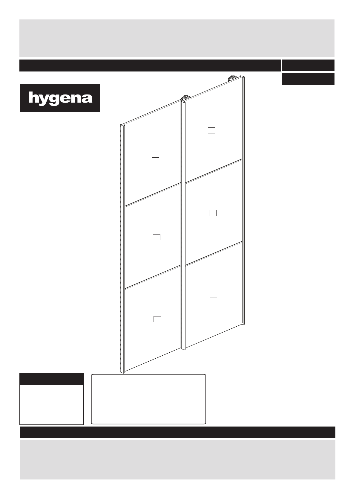
Bergen 180 High gloss doors
121
121
Assembly Instructions- Please keep for future reference
DR8250800
518/9696
517/9101
High gloss doors
Dimensions
Width - 180cm
Depth - 6.7cm
Height - 195.2cm
Tip : To prevent damage,
we recommend that you
build your unit on the
carton(s) it was packed in.
Dimensions
518/9696 WHITE HG
517/9101 CAHMERE HG
Important – Please read these instructions fully before starting assembly
If you need help or have damaged or missing parts, please visit: www.argos-support.co.uk
or email: Help@ClickSpares.co.uk (quoting your original order number)
Alternatively, call the Spares Helpline on: 0370 112 1928
For any other queries please contact the Customer Helpline on: 0345 640 2020
Issue 4 - 10022016
Page 2
Safety and Care Advice
Important – Please read these instructions fully before starting assembly
• Check you have all the
components and tools listed on
pages 2 and 3.
• Remove all fittings from the
plastic bags and separate them
into their groups.
• Keep children and animals
away from the work area, small
parts could choke if swallowed.
• Make sure you have enough
space to layout the parts before
starting.
Care and maintenance
• Only clean using a damp cloth
and mild detergent, do no use
bleach or abrasive cleaners.
• Do not stand or put weight on
the product, this could cause
damage.
• Assemble the item as close
to its final position (in the same
room) as possible.
• Assemble on a soft level
surface to avoid damaging the
unit or your floor.
• Parts of the assembly will be
easier with 2 people.
• From time to time check that
there are no loose screws on
this unit.
•To reduce the
likelihood of
damaging your
product please
ensure that your
power drill is set on a low torque
setting.
• Dispose of all packaging
carefully and responsibly.
• This product should not be
discarded with household
waste. Take to your local
authority waste disposal centre.
Handy Hints
• Assemble all parts and bolts
loosely during assembly, only
once the product is complete
should you fully tighten the bolts
Instruction video
• This manual is provided with an additional instruction
video. If the icon on the right is displayed at a particular
step in the manual, Follow the link: http://nlink.nu/vid02
Or scan the QR code on the left with your phone.
• Regularly check and ensure
tightend properly.
See page 2 for link
to instruction video!
Note: if required the next
page can be cut out and used
as reference throughout the
assembly. Keep this page with
these instructions for future
reference.
2
Page 3
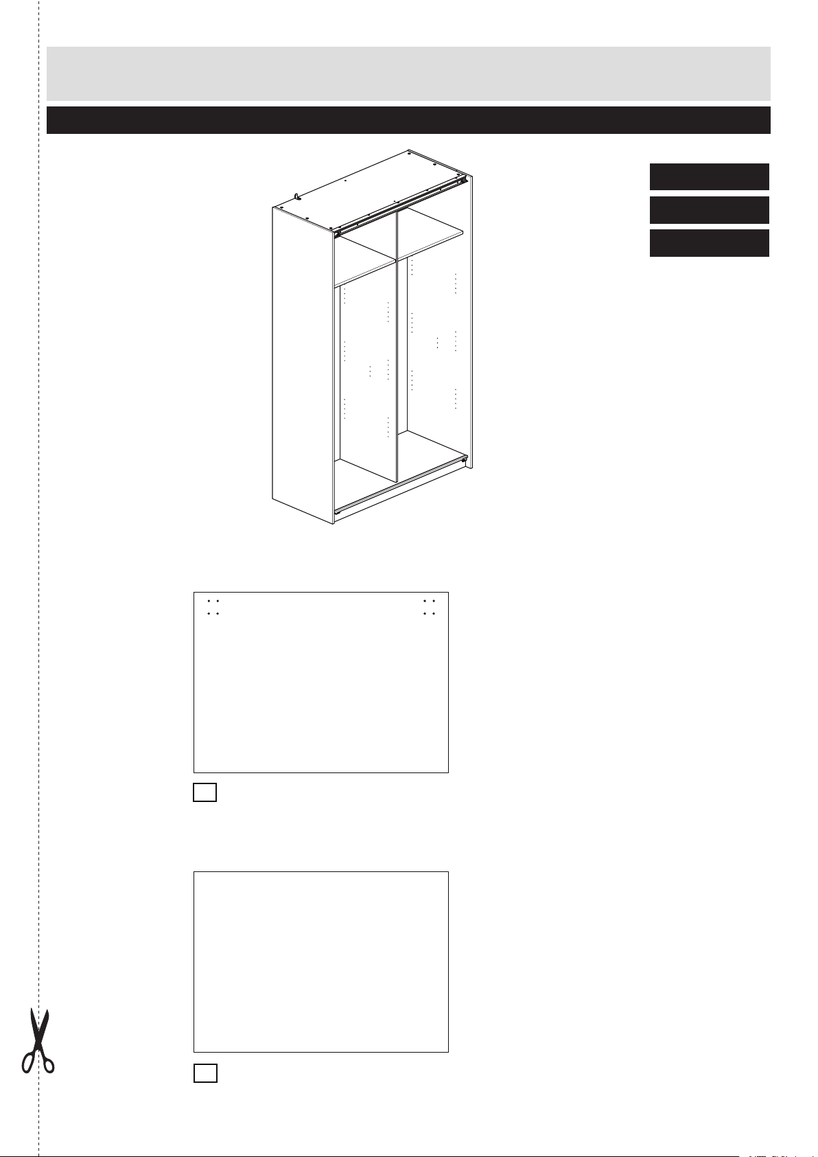
Components - Panels
For damaged or missing parts, please visit:
www.argos-support.co.uk or email: Help@ClickSpares.co.uk
Please check you have all the panels listed below
Cabinet supplied separately
249/4834
248/6921
226/8730
Segment x4
1
(91.5 x 65cm)
P3355
Segment middle x2
2
(91.5 x 65.1cm)
P3356
3
Page 4
For damaged or missing parts, please visit:
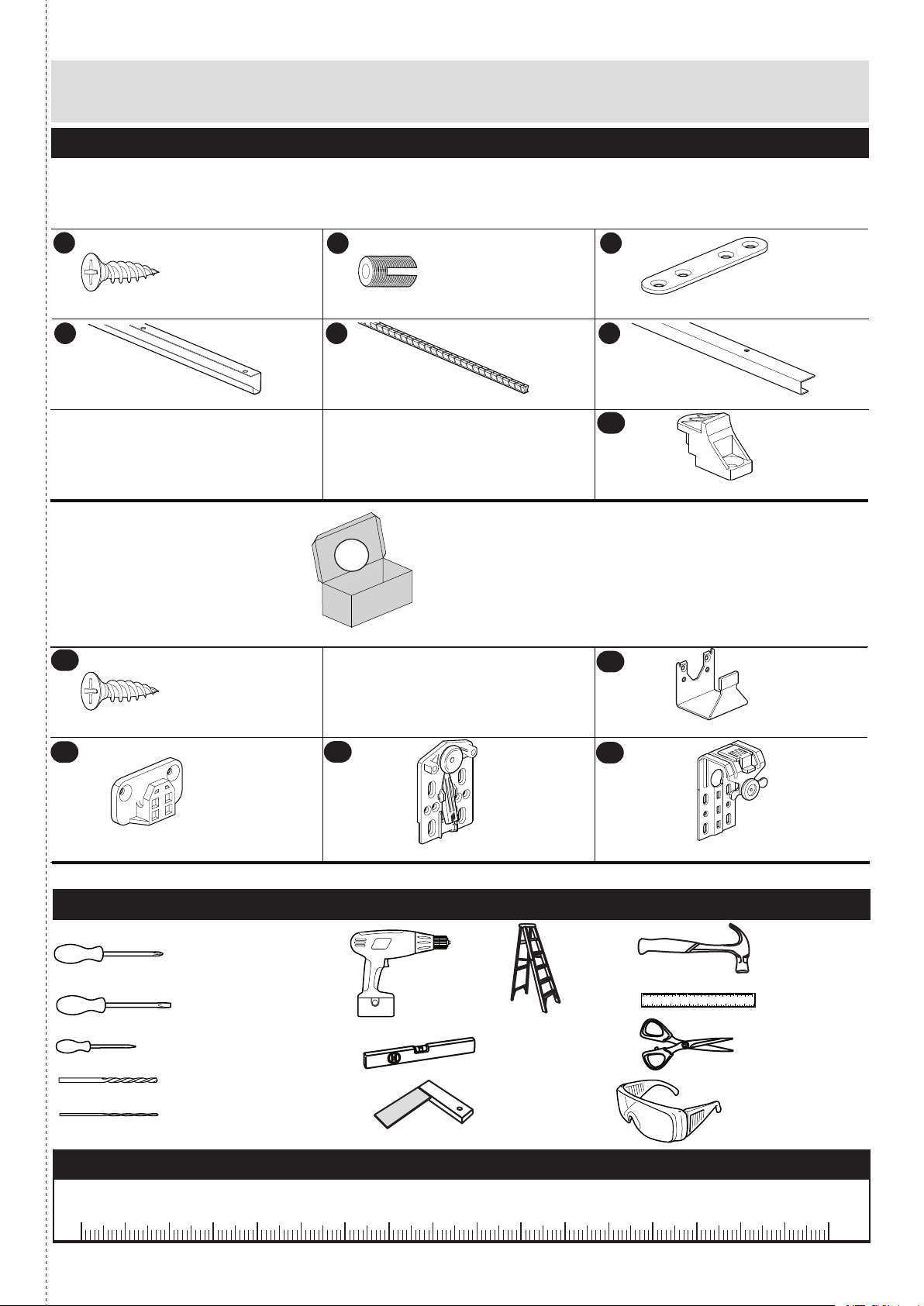
Components - Fittings
www.argos-support.co.uk or email: Help@ClickSpares.co.uk
Please check you have all the fittings listed below
Note: The quantities below are the correct amount to complete the assembly. In some cases more fittings
may be supplied than are required.
D
Screw x 72 (4x12.5mm)
S
Door handle x 3 (1951mm)
AC
FK1309
PM1652B
ZF9997L
E
Plug, Nylon x 32
T
Brush x 3 (1951mm)
A
(5x9mm)
FK1082
PM1652C
O
Connecting plate x 8
U
Door trim x 1 (1951mm)
AE
Spacer x 1
AI
FK1236
PM1652D
ZF9997F
ZF9997C
Screw x 33 (4x15mm)
AJ
Back guide part x 2
ZF9998D
AK
Sliding door connecting plate x 2
Tools required
Phillips screwdriver
(medium & large)
Drill
Flatblade screwdriver
(medium)
Piercer
(small)
Spirit level
5mm Suitable drill bit
5mm Suitable drill bit
Setsquare
Ruler - Use this ruler to help correctly identify the screws
ZF9997B
Stairs
Front guide part x 2
AL
ZF9997A
Sliding door connecting bracket x 2
Small
hammer
0 10 20 30 40 50 60 70 80 90 100 110 120 130 140 150
0 1 2 3 4 5 6
Ruler/tape
measure
Scissors
Eye protection
(when using a
hammer or drill)
0 5 10 15 20 25 30 35 40 45 50 55 60 65 70 75 80 85 90 95 100
4
105
110 115 120 125 130 135 140 145 150 155 160 165 170
Page 5

1112112
1
Assembly Instructions
E
E
UUSDDDDDDDDDDDDDDDDDDDD
D
Step 2
3 Segment slide door left
a: Put 8x nylon plug E
into the segment 1.
Use a small hammer.
Repeat this step.
a:
2x
b: Mount door trim U with
3x screws D on segment
1.
Note: there should be no
gap between doorsegment
1and door trim U.
c: Mount segment middle
2 with 3x screws D on
door trim U.
Mount segment 1 with
4x screws D on
door trim U.
b:
No Gap
between metal profiles
and door panel!
c:
d: Mount door handle S
on segment 1 with 4x
screws D and on middle
segment 2 with 3x
screws D.
Note: there should be no
gap between doorsegment
1 and door handle S.
d:
5
Page 6

Assembly Instructions
11211
S
T
AC
AJ
AC
AKAKACACACACACAJAJACACACAC
TOODDDD
SAEOODDD
D
Step 2
3 Segment slide door left
e: Mount 4x connecting
plate O, each with 2x
screws D on segment
1 and 2x screws D on
middle segment 2.
Remove protective film
from door handle S.
Stick 1x brush T onto
door handle S by partially
removing the cover from
adhease as brush is
applied.
f: Upside.
Mount 2x Sliding door
connecting plate k
squarely by using the
guidemarks in the plate
k, each with 6x screws
c on segment 1.
Attach 1x spacer e with
1x screw c on the
brush side sliding door
connecting plate k.
Please remove
the protective film!
e:
See page 2 for link
to instruction video!
f:
g: Underside.
Mount 2x back guide
part j , each with 2x
screws c on segment 1.
6
g:
x2
Page 7

121
Assembly Instructions
AJ
AJ
RRR
Step 3
Place left slide door
2 People are required for
step 3a and 3b.
Hook the 2x back guide
a:
part j into the plastic
guide rail R.
See page 2 for link
to instruction video!
a:
a: Detail.
The hook of the back guide
part j should be in the
front guide of the plastic
guide rail R
7
Page 8

Assembly Instructions
121
QQQ
Q
AKAKAK
Step 3
Place left slide door
b: Hook Sliding door
connecting platek
on metal guide rail Q.
b:
b: Detail.
The wheel of the sliding
door connecting plate k
should be in the front
guide of the metal guide
rail Q.
To lock the door, lock the
Sliding door connecting
plate k on the guide
railQ with the locking pawl.
push the yellow
lock pin to
secure part
k to rail
8
Page 9

Assembly Instructions
1121112
1
E
E
SSSDDDDDDDDDDDDDDDDDDDDDD
Step 4
Step 4
3 Segment slide door right
3 Segment slide door right
a: Put 8x nylo
a: Put 8x nylon plug E
the segment 1.
into
Use a small hammer.
the segment 3.
Repeat this step.
Use a small hammer.
Repeat this step.
b: Mount door handle S
b: Mount door handle S
with 4x screws D on
with 4x screws D on
segment 1 .
segment 3 .
Note: there should be no
Note: there should be no
gap between doorsegment
gap between doorsegment
1 and door handle S.
3 and door handle S.
(see m).
a:
2x
b:
c: Mount segment middle
c: Mount segment middle
2 with 3x screws D on
4 with 3x screws D on
door handle S.
door handle S.
Mount segment 1 with
Mount segment 3 with
4x screws D on door
4x screws D on door
handle S.
handle S.
d: Mount door handle S
d: Mount door handle S
on segment 1 with 4x
on segment 3 with 4x
screws D and on middle
screws D and on middle
segment 2 with
segment 4 with
3x screws D.
3x screws D.
No Gap
between metal profiles
and door panel!
c:
d:
Note: there should be no
Note: there should be no
gap between doorsegment
gap between doorsegment
1 and door handle S.
3 and door handle S.
(see m).
9
Page 10

Assembly Instructions
11211
TOODDDDSO
O
D
D
D
D
T
S
T
ACACACACACACAC
AC
ALALAI
AIx2AC
AI
Step 4
Step 4
3 Segment slide door
right
e: Mount 4x connecting
plate O, each with 2x
screws D on
segment 3 and
2x screws D on middle
segment 4.
Please remove
Remove protective film
from door handle S.
Stick 2x brush T onto 2x
door handle Sby partially
remove the cover from
adhease as brush is
applied.
the protective film!
e:
See page 2 for link
to instruction video!
f: Upside.
Mount 2x sliding door
connecting bracket l
squarely by using the
guidemarks in the plate
l,
each with 6x screws c
on segment 3.
g: Underside.
g: Underside.
Mount 2x front guide
Mount 2x front guide
part i , each with 2x
part i , each with 2x
screws c on
screws c on
segment 1.
segment 3
f:
g:
10
Page 11

Assembly Instructions
R
RAIR
112
Step 5
Place right slide door
a: Hook the 2x front guide
part i into the plastic
guide rail R.
See page 2 for link
to instruction video!
a:
a: Detail.
The hook of the rear guide
part i should be in the
front guide of the plastic
guide rail R
11
Page 12

Assembly Instructions
QQQ
Q
ALALAL
112
Step 5
Place right slide door
b: Hook the sliding door
connecting bracketl
on metal guide rail Q.
a:
b: Detail.
The wheel of the sliding
door connecting bracket
l should be in the rear
guide of the metal guide
rail Q.
To lock the door, lock the
sliding door connecting
bracket l on the
guide rail Q with the
locking pawl.
12
 Loading...