

Page 1
Important - Please read these instructions fully before starting assembly
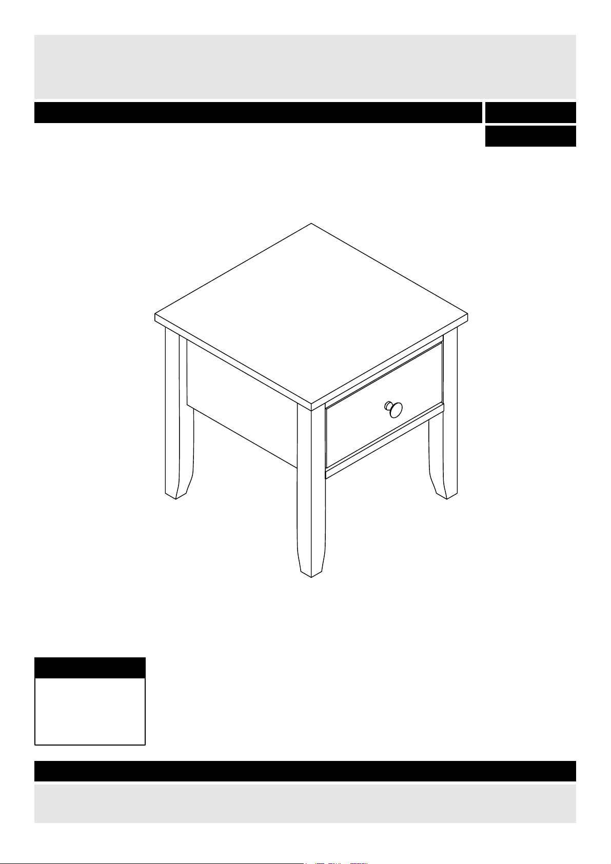
Dimensions
Issue 1 -18/10/11
Width - 45cm
Depth - 45cm
Height - 45cm
Henley End Table
Assembly Instructions - Please keep for future reference
614 / 3150
If you need help or have damaged or missing parts, call the Customer Helpline: 08456 400800
614 / 3167
Page 2
1
Safety and Care Advice
!
Important - Please read these instructions fully before starting assembly
Care and maintenance
• Clean using a damp cloth or a
proprietary domestic furniture
polish. Do not use abrasive
cleaners.
• This product should not be
discarded with household waste.
Take to your local authority waste
disposal only.
• Keep these instructions for
future use.
• Check you have all the
components and tools listed on
pages 2 and 3.
•Do not stand or put excessive
weight on the product, this
could cause damage.
• Parts of the assembly will be
easier with 2 people.
• Dispose of all packaging
carefully and responsibly.
• To ensure an easier assembly,
we strongly advise that all fittings
are only finger tightened during
initial assembly. Only upon
completion of the assembly
should all fixing points be fully
tightened.
• Do not use this item if any
components are missing or
damaged.
• During assembly children
should be kept away from the
product due to possible risk of
injury.
• Remove all fittings from the
plastic bags and separate them
into their groups.
• From time to time check that
there are no loose screws on
this unit.
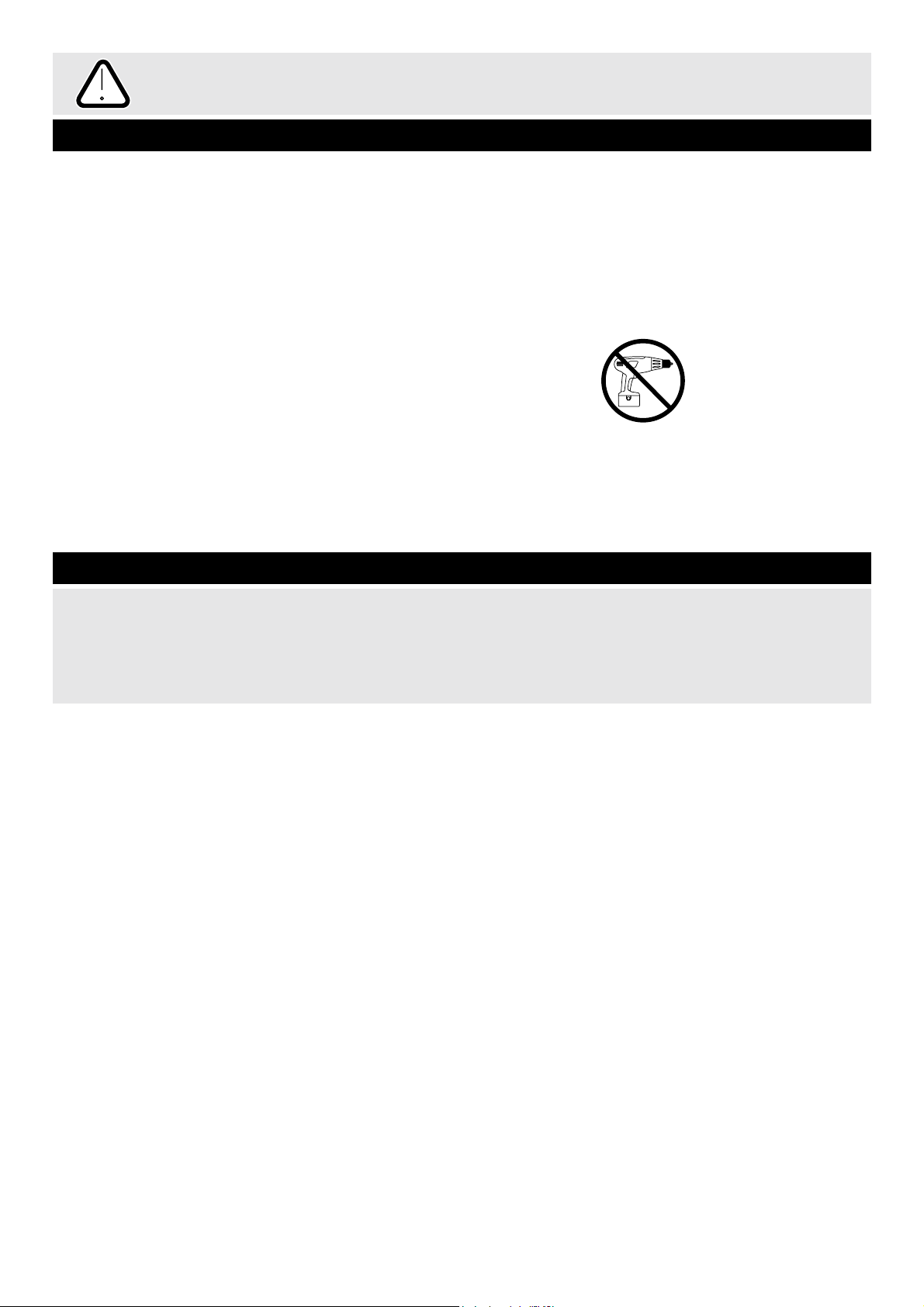
• We do not
recommend the
use of power
drill/drivers for
inserting screws,
as this could damage the unit.
Only use hand screwdrivers.
Page 3
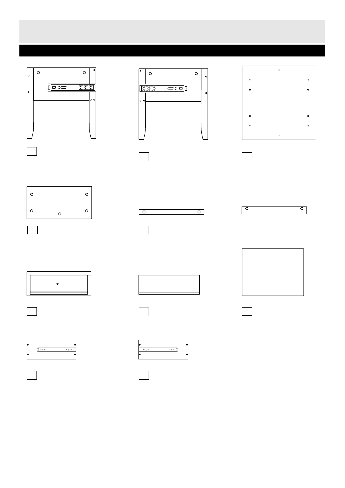
Please check you have all the parts listed below
Components - Parts
If you have damaged or missing components,
call the Customer Helpline: 08456 400800
2
1
Side panel ( right )
(42 x 43 .2cm)
3
Top panel (45 x 45cm)
2
Side panel ( left )
(42 x 43 .2cm)
4
Back panel
(34 x 19. 8cm)
Underside
Inside
Inside
7
Drawer front
(33.4 x 14.8cm)
8
Drawer back
(29 x 11.8cm)
9
Drawer base
(30 x 28.6cm)
10
Drawer side panel (left)
(30 x 11.8cm)
11
Drawer side panel (right)
(30 x 11.8cm)
Inside
Inside
5
Upper stretcher
(34 x 3cm)
6
Lower stretcher
(34 x 4.5cm)
Page 4

Please check you have all the fittings listed below
Components - Fittings
3
Note: The quantities below are the correct amount to complete the assembly. In some cases more fittings
may be supplied than are required.
Ruler - Use this ruler to help correctly identify the screws
0
5
10 15 20 25 30 35 40
45
50
55
60 65 70
75
80 85 90 95 100 105 110 115 120 125 130 135 140 145 150 155 160 165 170
Tools required
A B C
Metal dowel x 13
D E F
0
0 5 10 15 20 25 30 35 40 45 50 55 60 65 70 75 80 85 90 95 100 105110 115 120 125130 135 140145 150
1 2 3 4 5 6
Phillips screwdriver
(medium & large)
Ruler/tape
measure
Wood dowel x 6 Locking nut x 13
19mm Screw x 1
25mm Screw x 9
Drawer handle x 1
Page 5

4
Step 1
Preparing panels
Place left and right side
panels and and
top panel flat on the
floor with the fixing holes
facing up.
Screw metal dowels
into panels , and
as shown.
Note: Insert metal
dowels as far as shown.
Do not overtighten.
Insert wood dowels
into panels and
as shown.
A
Assembly Instructions
1
2
3
1
2
3
B
1
A
Front
Back
A
B
A
1
3
B
A
A
A
B
B
B
B
3
Top
Bottom
A
A
A
A
2
Bottom
Top
Underside
Page 6

Assembly Instructions
5
Step 2
Step 3
C C
C C
1
4
6
5
1
C
C
C
Attaching back panel
Locate back panel
onto right side panel .
Note: Ensure the fixing
holes are facing in as
shown.
Insert locking nuts into
the holes in back panel
as shown.
Using a screwdriver, turn
locking nuts clockwise
to secure.
4
1
Holes to face inside
C
4
C
Attaching stretchers
Locate upper stretcher
onto right side panel .
Locate lower stretcher
onto right side panel .
Note: Ensure the fixing
holes in both stretchers
are facing down.
Insert locking nuts into
the holes in the underside
of stretchers and
as shown.
Using a screwdriver, turn
locking nuts clockwise
to secure.
5
1
Holes to
face down
6
1
C
6
5
C
Front
Back
Top
Bottom
Page 7

Assembly Instructions
6
Step 4
Step 5
C C
B
C
C
C
C
2
D
C
3
Attaching left side panel
Insert wood dowel
into the end of lower
stretcher as shown.
With help, carefully align
left side panel and
locate into position.
Insert locking nuts into
back panel and
stretchers and .
Turn locking nuts
clockwise to secure.
6
B
6
2
C
5
4
4
5
6
1
2
4
5
Front
Back
C
C C
Attaching top panel
Place top upside down
onto a clean flat surface.
With help, turn the unit
body upside down and
locate it onto top .
Insert locking nuts into
the holes in side panels
and and back
panel .
Turn locking nuts
clockwise to secure.
Finally secure top
using screw through
stretcher .
C
1 2
3
3
3
5
D
4
C
Page 8

Assembly Instructions
7
Step 6
Assembling drawer
a: Assemble drawer
side panels and
and drawer back
together using screws .
Note: Ensure the
grooves in all 3 panels
are aligned at the bottom.
b: Slide drawer base
into the grooves as
shown.
c: Assemble drawer
front using screws
.
Attach drawer handle
using screw .
a:
b:
c:
10
8
D
9
D
7
F
E
D
D
8
11
9
7
10
11
Align grooves
D
D
E
F
D
Page 9

Assembly Instructions
Step 8
Assembly is complete.
If you need help or have damaged or missing parts, call the Customer Helpline: 08456 400800
Justwise Group LTD., 6 The Shires, Shire Hill Industrial Estate, Saffron Walden Essex. CB11 3AP
8
Locating drawer
Carefully stand the unit
upright.
a: Fully extend all drawer
runners out as shown.
b: Carefully locate the
runners on the drawer,
into the runners on the
main unit.
a:
b:
Warning:
The table is
heavy!
Lift with care.
!
Pull out the side panel
drawer runners for proper
insertion of the drawers.
Line up the drawer runners
on the drawers on both
sides so that they enter
evenly into the extended
receiving runners as shown.
Gently push in the drawer
until the drawer is secure
and slides in and out
smoothly.
 Loading...