

Page 1
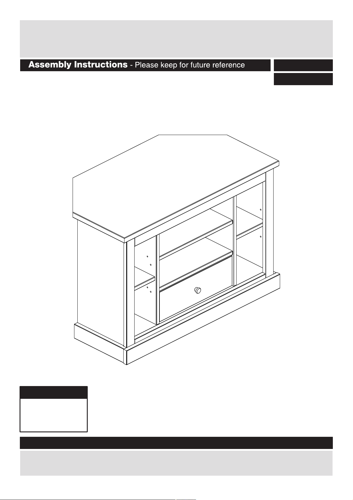
Harrington - 1 Drawer Corner TV Unit
614/4221
129/7908
Dimensions
Width - 90cm
Depth - 50cm
Height - 60cm
Important Please read these instructions fully before starting assembly
If you need help or have damaged or missing parts, call t h e A rgos Customer Helpline: 08456 400 800
or Homebase Customer Helpline: 0845 077 8888.
Issue 1 - 10/09/13
Page 2
Safety and Care Advice
Important – Please read these instructions fully before starting assembly
Check you have all the
components and tools listed on
pages 2 and 3.
Remove all fittings from the
plastic bags and separate them
into their groups.
Keep children and animals
away from the work area, small
parts could choke if swallowed.
Make sure you have enough
space to layout the parts before
starting.
Do not stand or put weight on
the product, this could cause
damage.
Assemble the item as close
to its final position (in the same
room) as possible.
Assemble on a soft level
surface to avoid damaging the
unit or your floor.
This product has been produced
from natural timber; you may
notice some variation in the grain
and colour of different component
parts which is normal for furniture
produced using natural wood and
is not the result of any
manufacturing fault.
The product has been treated
with a wax and oil finish to
prevent dirt ingress and preserve
moisture.
On unpacking the
furniture you may notice an
odour due to this treatment;
this will disappear once the
furniture is unpacked and
assembled after a period of time.
This process may leave some
staining on the packaging
material; please take care to
ensure this does not transfer
to clothing or carpeted surfaces
during assembly.
We do not
recommend the
use of power
drill/drivers
inserting screws,
as this could damage the unit.
Only use hand screwdrivers.
Parts of the assembly will be
easier with 2 people.
Dispose of all packaging
carefully and responsibly.
for
Care and maintenance
Use an appropriate furniture
polish for natural wood
furniture and a dry cloth to
clean the product.
Avoid placing the furniture in
direct sunlight as this will cause
the timber to prematurely age.
From time to time check
that there are no loose
screws on this unit.
This product should not be
discarded with household
waste. Take to your local
authority waste disposal
centre.
Note: If required the next page
can be cut out and used as
reference throughout the
assembly. Keep this page with
these instructions for future
reference.
1
Page 3
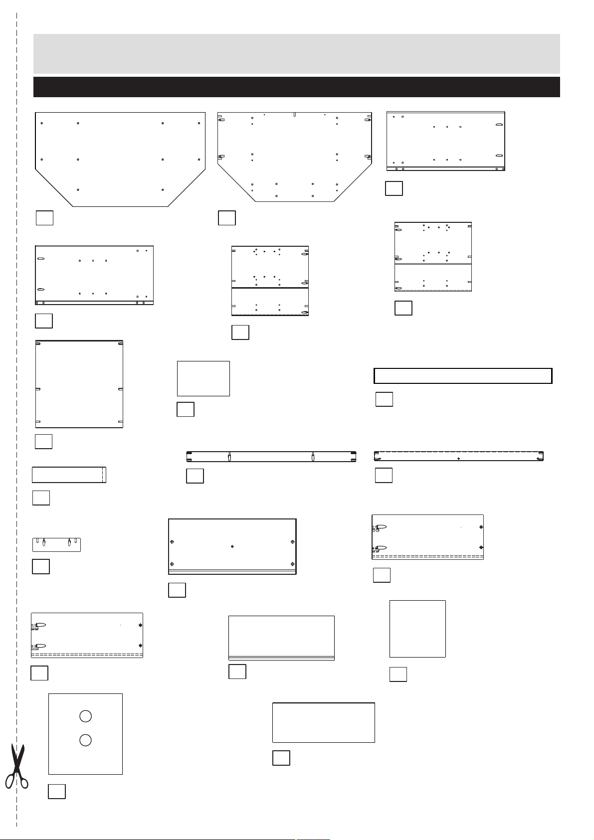
Components - Panels
Please check you have all the panels listed below
1
Top panel
4
Left side panel
7
Fixed shelf x2
(90 x 50cm)
(57,4 x 28,9cm)
(43 x 43cm)
2
Base panel
5
Right division
8
Removable shelf x2
11
Top front frame
(81,4 x 47,2cm)
(48,7 x 44cm)
(17,2 x 26cm)
(
76,2 x 4,6cm)
3
Right side panel
6
Left division
9
Front plinth
12
Bottom front frame
(57,4 x 28,9cm)
(48,7 x 44cm)
89,2 x 6,7cm)
(
(
76,2 x 4,6cm)
10
Side plinth x2 (
13
Foot
(
24 x 6,7cm)
16
Drawer left side (35 x 14cm)
28,9 x 6,7cm)
14
Drawer front (42,5 x 14,5cm)
17
Drawer back (39,3 x 14cm)
20
15
Drawer right side
18
Drawer bottom (34,7 x 40,3cm)
Back panel x2 (48,7 x 18,8cm)
(35 x 14 cm)
19
Back panel with hole (48,7 x 44,8cm)
2
Page 4
If you have damaged or missing components,
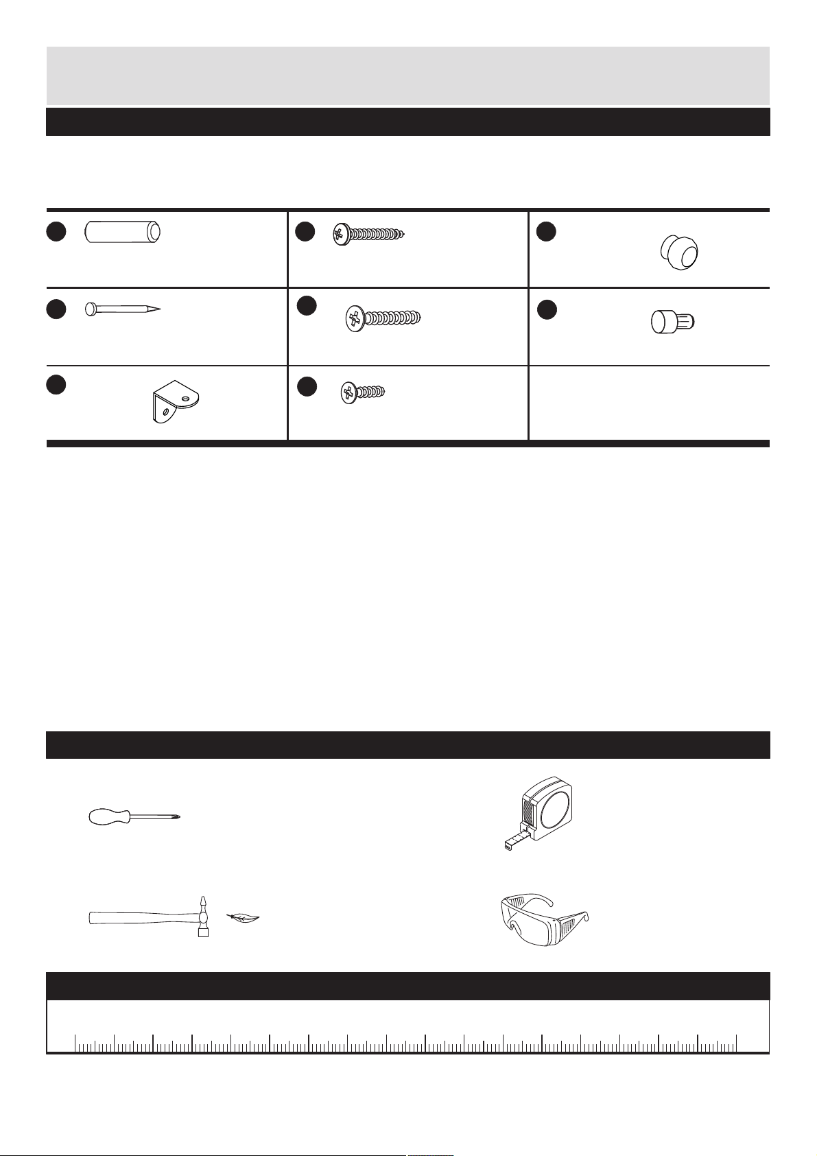
Components - Fittings
call the Argos Customer Helpline: 08456 400 800
or Homebase Customer Helpline: 0845 077 8888.
Please check you have all the fittings listed below
Note:
The quantities below are the correct amount to complete the assembly. In some cases more
fittings may be supplied than are required.
A B C
Wooden dowel x 49
30mm Screw x 33
Drawer
handle x 1
D
Nail x 30
G
Bracket x 2
E
35mm Screw x 19
H
16mm Screw x 4
F
Shelf support x 8
Tools required
Phillips screwdriver
(medium & large)
Small
hammer
Ruler- Use this ruler to help correctly identify the screws
5
0
10 15 20 25 30 35 40
3
55
45
50
60 65 70
75
80 85 90 95 100 105 110 115 120 125 130 135 140 145 150 155 160 165 170
m
2
Ruler/tape
measure
Eye protection
(when using a
hammer or glue)
Page 5

Assembly Instructions
Step 1
Insert dowels into the
indicated parts.
Insert shelf support pins
into side panels and
and divisions and .
A
3
5
6
F
F
A
5
A
13
(2x)
7
3
A
A
A
A
A
F
A
A
F
A
A
A
A
A
A
A
A
6
A
A
F
4
A
A
A
A
A
A
F
F
4
15
16
11
A
12
A
F
F
2
A
A
A
A
A
A
A
A
Step 2
Attach divisions and
to the fixed shelves
6
using long screws .
Please note the position
of the labels on painel .
Note! grooves on
divisions and
5 6
must be facing
outside and holes
facing up as showing
in the diagram.
5
7
E
7
E
E
E
7
side down
E
E
E
E
E
E
6
7
side down
E
5
E
E
Note the groove
4
Page 6

Assembly Instructions
Step 3
Fit base panel to the
2
assembled part and fix it
using screws .
E
E
2
E
E
E
E
E
Step 4
Fit left side panel to
the assembled part, then
attach it to the base panel
using screws .
2
Fix foot to the base
13
panel using screws .
Note: correct
position as shown in the
diagram before fixing.
4
B
B
B
4
B
B
B
13
5
Page 7

Assembly Instructions
Step 5
Fix brackets through
pre-drilled holes on base
panel using screws .
G
H
H
H
Step 6
a: Fit top front frame to
the assembled part.
Attention Make
sure holes on top front
frame are facing up.
b: Fit bottom front frame
to the assembled part.
Attention Make
sure the frame is
positioned as shown in
the diagram.
11
12
11
Attention!
View from behind!
a:
11
b:
12
Attention!
6
Page 8

Assembly Instructions
Step 7
a: Fit right side panel
to the front frames and
base panel, then fix it to
the base panel using
screws .
b: Fix bracket to the
bottom front frame
using screws as shown.
B
G
H
3
12
a:
3
B
H
b:
B
H
12
2
Step 8
Fixing sides and front
plinth.
a:Fix side plinths to
the side panels using
screws .
aligned to the bottom and
front edges of the side
panels.
B
Note:
side plinths are
b:Fix front plinth
to the bottom front frame
11
using screws .
Note:
Make sure front
plinth is aligned to the
bottom edge of the side
panels and in line to the
side plinths.
Chanfred
edges to be facing up.
9
10
Make sure
9
B
10
a:
9
b:
B
B
B
B
B
B
10
B
a:
7
Page 9

Assembly Instructions
Step 9
Fixing top panel
Important:
With help, carefully stand
the product upright.
1
With help, fit top panel
1
to the assembled part
then fix it using screws .
Insert dowels half way
A
B
through to the holes on
base panel, as shown in
the diagram.
B
B
B
B
B
B
B
A
A
B
Step 10
Position shelves into
place.
Chanfred edges
to be facing front.
8
8
8
8
Page 10

Assembly Instructions
Step 11
Fixing back panels.
Important:
Product be
upright and square when
back panels are attached.
Attach the back panels
19 20
and using nails .
MUST
D
20
D
D
D
D
D
20
D
D
D
D
D
D
19
D
D
D
D
D
D
D
D
Step 12
Drawer assembly.
a: Attach drawer sides
15
front
b:Slide drawer bottom
into slots.
c:
Position drawer back
in place, press the drawer
sides and fit it using
screws .
16
and to the drawer
14
using screws .
B
B
18
17
18
b:
D
c:
B
17
B
D
a:
15
B
16
B
14
d:Using screw attach
the drawer handle to
E
C
the drawer front.
9
d:
E
C
Page 11

Assembly Instructions
Step 13
Insert drawer into unit.
Assembly is complete.
If you need help or have damaged or missing parts, c a l l t h e Customer Helpline: 08456 400 800
10
 Loading...