

Page 1
MADE IN
BRITAIN
Dimensions
If you need help or have damaged or missing parts, please visit www.argos-support.co.uk
or email: Help@ClickSpares.co.uk (quoting your original order number)
Alternatively, call the Spares Helpline on: 0370 112 1928.
For any other queries please contact the Customer Helpline on: 0345 640 2020
Important - Please read these instructions fully before starting assembly
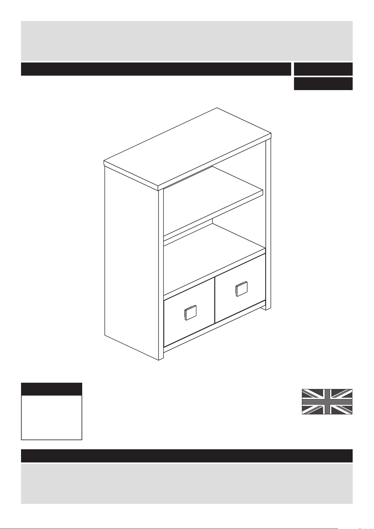
Eden - Low Display Unit
Assembly Instructions - Please keep for future reference
412/3062
411/3852
Width - 79.5cm
Depth - 38.1cm
Height - 123cm
Issue 1 - 22/07/15
Page 2

Safety and Care Advice
Important - Please read these instructions fully before starting assembly
• Warning: This unit weighs
approximately 24kgs.
Please lift with care.
• Check you have all the
components and tools listed on
pages 2 and 3.
• Remove all fittings from the
plastic bags and separate them
into their groups.
• Keep children and animals
away from the work area, small
parts could choke if swallowed.
• Parts of the assembly will be
easier with 2 people.
• Make sure you have enough
space to layout the parts before
starting.
• Do not stand or put weight on
the product, this could cause
damage.
• Assemble the item as close to
its final position (in the same
room) as possible.
• Assemble on a soft level
surface to avoid damaging the
unit or your floor (use opened
out unit carton).
1
Care and maintenance
• Only clean using a damp cloth
and mild detergent, do no use
bleach or abrasive cleaners.
• From time to time check that
there are no loose screws on
this unit.
• This product should not be
discarded with household
waste. Take to your local
authority waste disposal centre.
Note: If required the next page
can be cut out and used as
reference throughout the
assembly. Keep this page with
these instructions for future
reference.
• We do not
recommend the
use of power
drill/drivers for
inserting screws,
as this could damage the unit.
Only use hand screwdrivers.
• Safety note: It is
recommended that this unit is
secured to a wall using the
overbalance protector kit
supplied or, an alternative fixing
method of your choice.
• Dispose of all packaging
carefully and responsibly.
Page 3
Components - Panels
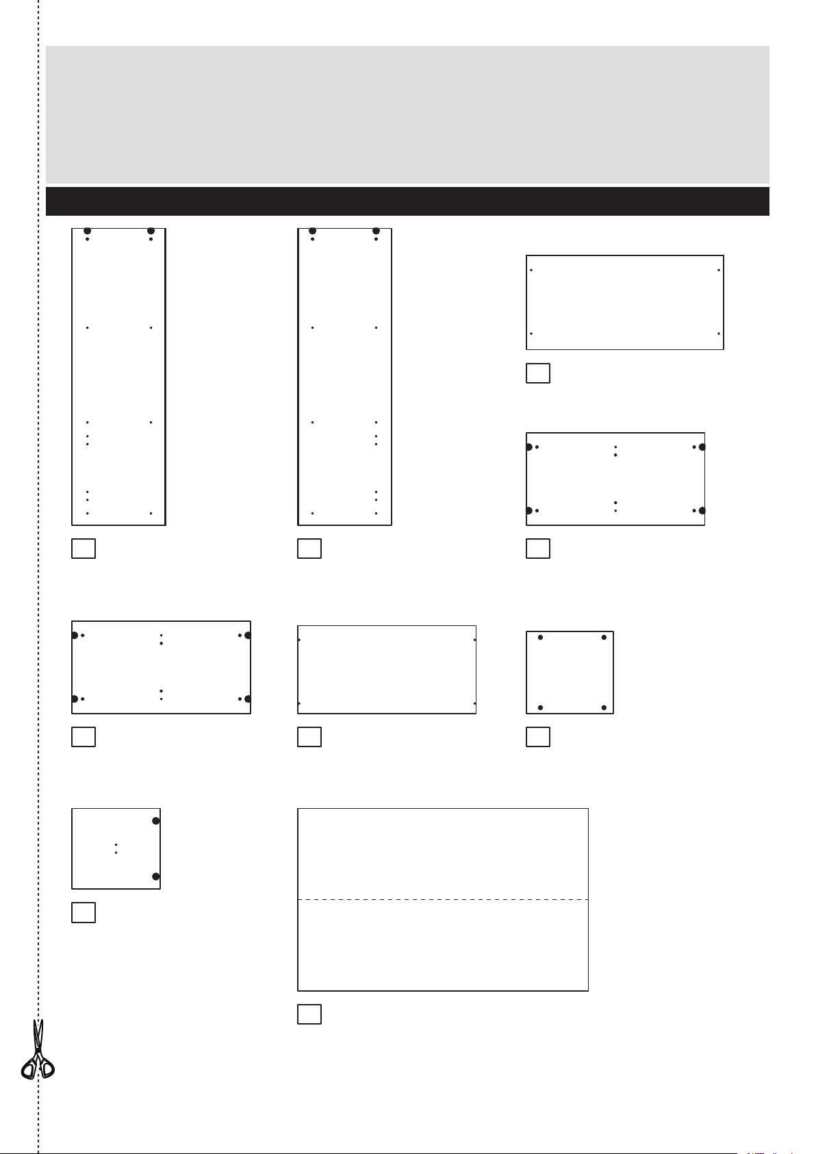
Please check you have all the panels listed below
If you need help or have damaged or missing parts, please visit www.argos-support.co.uk
or email: Help@ClickSpares.co.uk (quoting your original order number)
Alternatively, call the Spares Helpline on: 0370 112 1928.
For any other queries please contact the Customer Helpline on: 0345 640 2020
2
1
2 4
Door (DF3450)
(32.5 x 35.5cm) x 2
Left Side (DF3444)
(119.5 x 37.8cm)
Right Side (DF3445)
(119.5 x 37.8cm)
3
Top (DF3446)
(79.5 x 38.1cm)
Base (DF3449)
(71.9 x 37.2cm)
Fixed Shelf (DF3448)
(71.9 x 37.2cm)
Shelf (DF3447)
(71.9 x 35.4cm)
Divider (DF1237)
(33.1 x 35cm)
5
Back (X1170-735)
(117 x 73.5cm)
76
8
9
Page 4
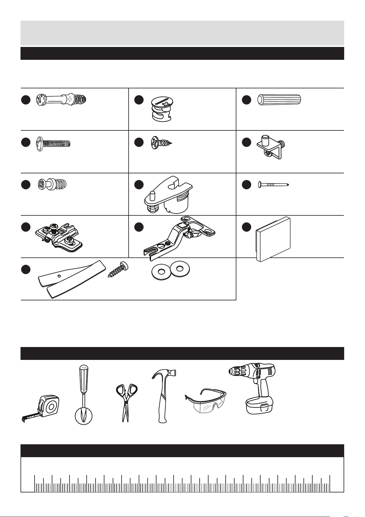
Please check you have all the fittings listed below
3
Components - Fittings
If you have damaged or missing components, call the
Customer Helpline: 03456 400800 quoting the reference
numbers below
Note: The quantities below are the correct amount to complete the assembly. In some cases
more fittings may be supplied than are required.
Ruler - Use this ruler to help correctly identify the screws
mm 10 20 30 40 50 60 70 80 90 100 110 120 130 140 150 160 170
D E F
G H
K
I
C
Tools required
19mm Screw (F461) x 4
Wooden dowel (F22) x 4
13mm Screw (F63) x 8
Shelf stud (F372) x 4
J
Hinge plate
(F523) x 4
Hinge (F522) x 4
Small metal dowel (F893) x 12
Hollow core
locking nut
(F892) x 12
B
Large locking
nut (F900) x 4
A
Metal dowel (F901) x 4
L
Handle (F414) x 2
M
Strap Screw Washer x 2
Overbalance protector kit (F269) x 1
Rule Scissors Hammer
Eye protection
(when using a
hammer or drill)
Cross-head
screwdriver
Electric drill
(do not use for
fitting screws)
Nail (F51) x 24
Page 5
C
C
Assembly Instructions
4
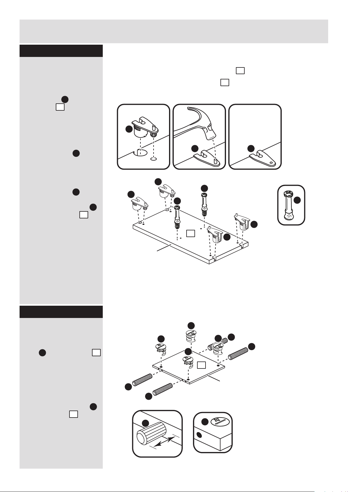
Step 1
H
H H
Prepare the fixed
shelf
Push 4 hollow core
locking nuts into the
fixed shelf , making
sure that they are flush
against the panel’s
surface.
Using a hammer, tap in
the pin on the hollow
core locking nut .
Note: The pin should be
tapped in flush with the
top surface of the hollow
core locking nut .
Screw 2 metal dowels
into the fixed shelf .
Note: Tighten the metal
dowels up fully against
the panels.
H
H
5
H
A
5
H
H
H
H
Note: The base and fixed shelf panels are similar.
The 4 holes in the middle of the fixed shelf are only part-drilled.
The 4 holes in the middle of the base are drilled all the way through.
5
A
A
A
B
B
B
Prepare the divider
Insert 4 large locking
nuts into the divider .
Note: The arrow on the
locking nut must point
towards the hole in the
edge of the panel.
Tap 4 wooden dowels
into the divider .
Note: Wooden dowels
must not stick out from
the edge by more than
10mm or they may
damage other panels.
B
B
C
10mm
C
C
Step 2
B
7
7
C
7
5
4
Finished
front edge
Finished
front edge
Page 6

Finished
front edge
Finished
front edge
Assembly Instructions
5
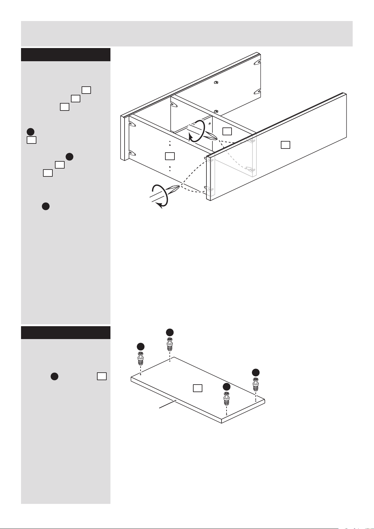
Step 3
Step 4
Fit the divider to the
fixed shelf
Push the divider onto
the fixed shelf .
Use a screwdriver to
tighten the 2 large
locking nuts fitted to
the divider .
Note: Turn the large
locking nuts as far as
they will go - more than
1/2 a turn.
5
7
B
B
5
A
B
5
7
Prepare the base
Push 4 hollow core
locking nuts into the
base , making sure
that they are flush
against the panel’s
surface.
Using a hammer, tap in
the pin on the hollow
core locking nut .
Note: The pin should be
tapped in flush with the
top surface of the hollow
core locking nut .
Turn the base over
Screw 2 metal dowels
into the base .
H
H
4
H
A
4
H
H
H
Turn the base over
H
A
A
4
4
Finished
front edge
Finished
front edge
Page 7

Finished
front edge
Assembly Instructions
6
Step 5
7
4
Fit the base
Push the base onto
the divider .
Use a screwdriver to
tighten the 2 large
locking nuts fitted to
the divider .
7
4
B
7
H
H
J
Finished
front edge
G
G
G
G
J
J
F
F
Step 6
Prepare the right side
Push 2 hollow core
locking nuts into the
right side , making
sure that they are flush
against the panel’s
surface.
Using a hammer, tap in
the pin on the hollow
core locking nut .
Screw 4 small metal
dowels into the right
side .
Push 2 shelf studs
into the right side .
Fit 2 hinge plates onto
the right end , making
sure that the slot is
facing towards the
finished front edge.
H
H
2
G
2
2
F
J
2
2
Page 8

Finished
front edge
J
Assembly Instructions
7
Step 7
Step 8
Fit the right side
Push the right side
onto the base and
fixed shelf .
The 4 small metal dowels
. fitted to the right side
. must slide into the
top of the 4 hollow core
locking nuts fitted to
the base and fixed
shelf . .
Insert a screwdriver into
the 4 hollow core locking
nuts and turn the nuts
inside as far as they will
go.
G
H H
2
5
4
G
2
H
4
5
H
2
5
4
H
H
G
G
G
F
F
J
G
J
Prepare the left side
Push 2 hollow core
locking nuts into the
left side , making sure
that they are flush
against the panel’s
surface.
Using a hammer, tap in
the pin on the hollow
core locking nut .
Screw 4 small metal
dowels into the left
side .
Push 2 shelf studs
into the left side .
Fit 2 hinge plates onto
the left end , making
sure that the slot is
facing towards the
finished front edge.
H
H
1
G
1
1
F
J
1
1
Page 9
Assembly Instructions
8
Step 9
Fit the left side
Push the left side
onto the base and
fixed shelf .
The 4 small metal dowels
. fitted to the left side
. must slide into the
top of the 4 hollow core
locking nuts fitted to
the base and fixed
shelf . .
Insert a screwdriver into
the 4 hollow core locking
nuts and turn the nuts
inside as far as they will
go.
1
5
4
G
1
H
4
5
H
1
5
4
Step 10
Prepare the top
Screw 4 small metal
dowels into the top .
G
G
G
G
G
3
3
Finished
front edge
Page 10

yy
xx
yy
xx
Assembly Instructions
9
Step 11
Step 12
Fit the top
Push the top onto the
left side and right
side .
The 4 hollow core
locking nuts fitted to
the left side and right
side must slide over
the 4 small metal dowels
. fitted to the top . .
Insert a screwdriver into
the 2 hollow core locking
nuts and turn the nuts
inside as far as they will
go.
2
1
3
H
1
2
G
4
H
2
1
3
Fit the back
a: Square up the unit by
making sure that
measurement x to x
equals y to y.
b: Place the back
onto the unit.
Nail around the
outside edges of the
back .
Note: Nails should be
spaced about 150mm
apart.
Stand the unit up for
the next step.
9
I
The measurement from top corner X to bottom corner X must be
equal to the measurement from top corner Y to bottom corner Y
a:
9
Warning: The
unit is heavy.
Lift with care.
b:
I
9
Page 11

Assembly Instructions
10
Step 13
Fit the shelf
Lower the shelf down
onto the 4 shelf studs .
Tighten the screws in the
shelf studs up into the
shelf .
F
6
6
F
6
Prepare the 2 doors
Push fit 2 hinges into
each of the 2 doors .
Secure each hinge with
2 screws .
Note: Before securing
with the screws, make
sure that the hinges are
positioned at 90 degrees
with the edge of the
door.
E
K
90
K
Step 14
K
E
E
K
E
E
K
E
E
K
E
E
8
8
8
Finished
front edge
Page 12

Assembly Instructions
11
Step 15
6
Fit doors and handles
Note: The easiest way to
attach each door is
to fit the top hinge first,
then align and fit the
bottom hinge.
a: Push the hinge
onto the front part of the
hinge plate .
b: Keep the hinge
FLAT against the hinge
plate as you slide it
across as far as it will go.
Tighten screw A.
c: The hinge must be
flat against the hinge
plate prior to any
adjustment.
d: The hinge must
NOT be AT AN ANGLE
to the hinge plate
when assembled.
This would indicate that
the recess at the bottom
of screw B had not
located in the slot in the
hinge plate and the hinge
would not be secure.
Remove the hinge from
the hinge plate and then
re-assemble being
careful to follow
instructions a-c.
e: Attach a handle to
each of the 2 doors
using screws .
K
K
K
J
J
J
K
J
L
D
8
a: b:
c: d:
J
K
J
J
B
J
K
K
K
A
K
J
B
e:
8
D
D
L
L
8
8
Page 13

12
Step 16
Assembly Instructions
b:
c:
d:
a:
Adjust the doors if
needed
a: Before adjusting the
doors, use a spirit level
to check the base (or
top) of the unit is level,
front-to-back and
side-to-side in the 3
positions shown.
Use suitable packing
pieces (not supplied) to
make the unit level
BEFORE making any
adjustment to the hinges,
as shown.
b: Height adjustment.
Loosen screws A on
hinge plates and move
door up or down as
required.
Retighten screw A.
c: Forward and Back
adjustment.
Loosen screw B on hinge
plate and move door in
or out as required.
Retighten screw B.
d: Sideways
adjustment.
To move door ‘out’
loosen screw C.
To move door ‘in’ tighten
screw C.
A
A
B
C
Page 14

Assembly Instructions
13
Step 17
If you need help or have damaged or missing parts, please visit www.argos-support.co.uk
or email: Help@ClickSpares.co.uk (quoting your original order number)
Alternatively, call the Spares Helpline on: 0370 112 1928.
For any other queries please contact the Customer Helpline on: 0345 640 2020
Fit the overbalance
protector kit
To prevent possible
overbalancing we
recommend that this unit
is secured to a suitable
wall by fitting of the
overbalance protector kit
. to the unit, or an
alternative fixing method
of your choice.
Wall fixings are not
supplied as they will
need to suit the wall
type.
Note: Take care when
drilling the wall that you
do not drill into any
pipes, wires etc.
If in doubt, consult an
expert.
Assembly is complete
M
Attach the
strap to the unit
Attach the
strap to the wall
Wall fixing
(not supplied)
Washer
Strap
Strap
M
M
Example
Screw
(not supplied)
Washer
Screw
UNIT
Page 15

Page 16

ALR3158
 Loading...