

Page 1
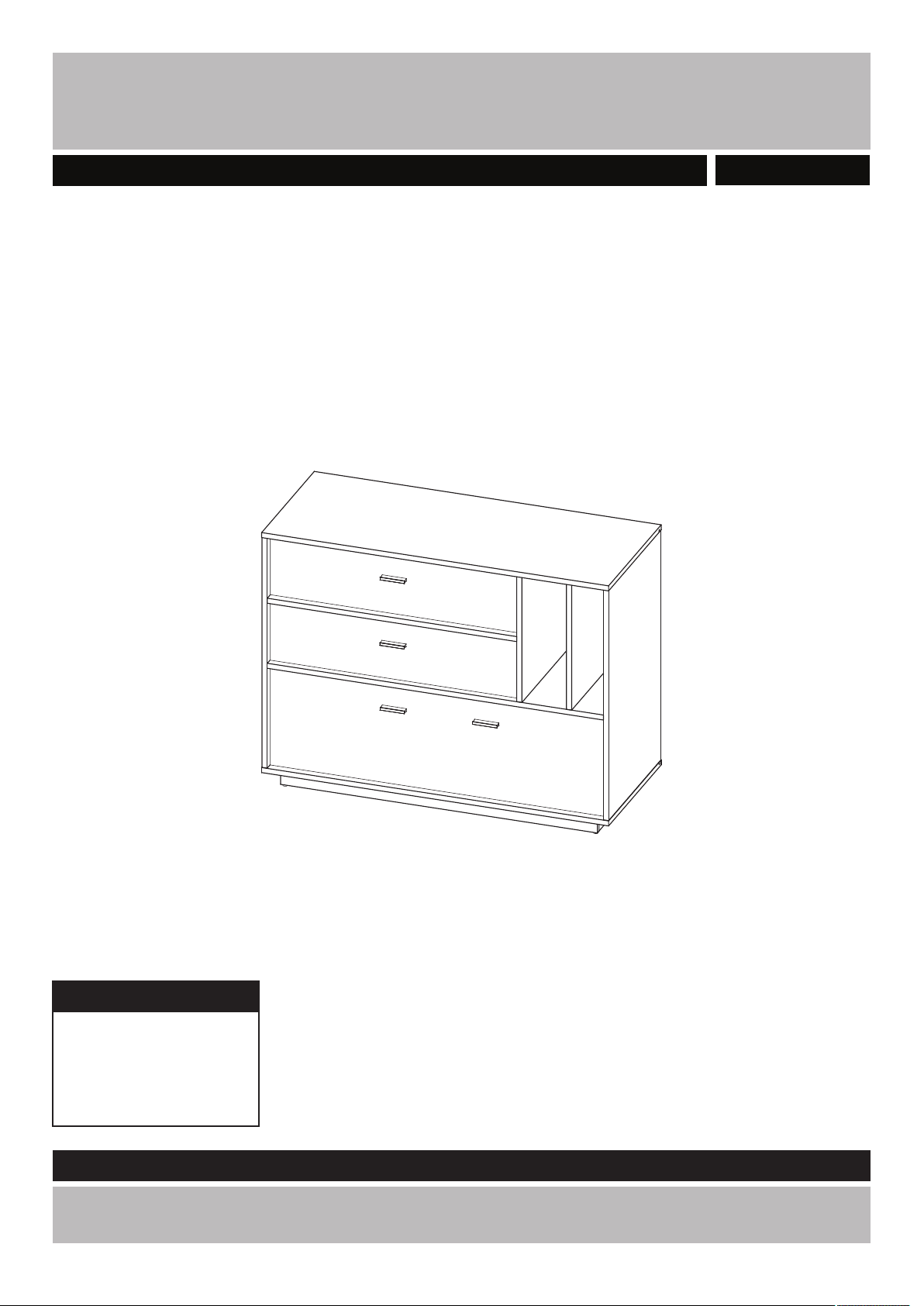
Darcy - 1 Door 2 Drawers Sideboard
Assembly Instructions - Please keep for future reference
424/5366
Dimensions
Width - 120 cm
Depth - 50 cm
Height - 91.6 cm
Important - Please read these instructions fully before starting assembly
If you need help or have damaged or missing parts, call the Customer Helpline: 0845 6400 800
Issue 1 -03/06/2015 1
Page 2
!
Safety and Care Advice
Important - Please read these instructions fully before starting assemb ly
• Check you have all the
components and tools listed on
pages 3 and 4.
• Remove all fittings from the
plastic bags and separate them
into their groups.
• Keep children and animals
away from the work area, small
parts could choke if swallowed.
• Make sure you have enough
space to layout the parts before
starting.
• Do not stand or put weight
on the panels during assembly,
this could cause damage.
• Assemble the unit as close
to its final position (in the same
room) as possible.
• Assemble on a soft level
surface to avoid damaging the
unit or your floor.
• Parts of the assembly will be
easier with 2 people.
• If using power tools, please
follow the safety instructions
supplied with the tools.
• We do not
recommend the
use of power drill/
drivers for inserting
screws, as this
could damage the unit. Only use
hand screwdrivers.
• Dispose of all packaging
carefully and responsibly.
• Warning: The unit weighs
approximately 57 kgs.
Please lift with care.
Care and maintenance
• Only clean using a damp cloth
and mild detergent, do no use
bleach or abrasive cleaners.
2
• From time to time check that
there are no loose screws on
this unit.
• This product should not be
discarded with household
waste. Take to your local
authority waste disposal centre.
Note: if required the next
page can be cut out and used
as reference throughout the
assembly .Keep this page with
these instructions for future
reference.
Page 3
If you have damaged or missing components
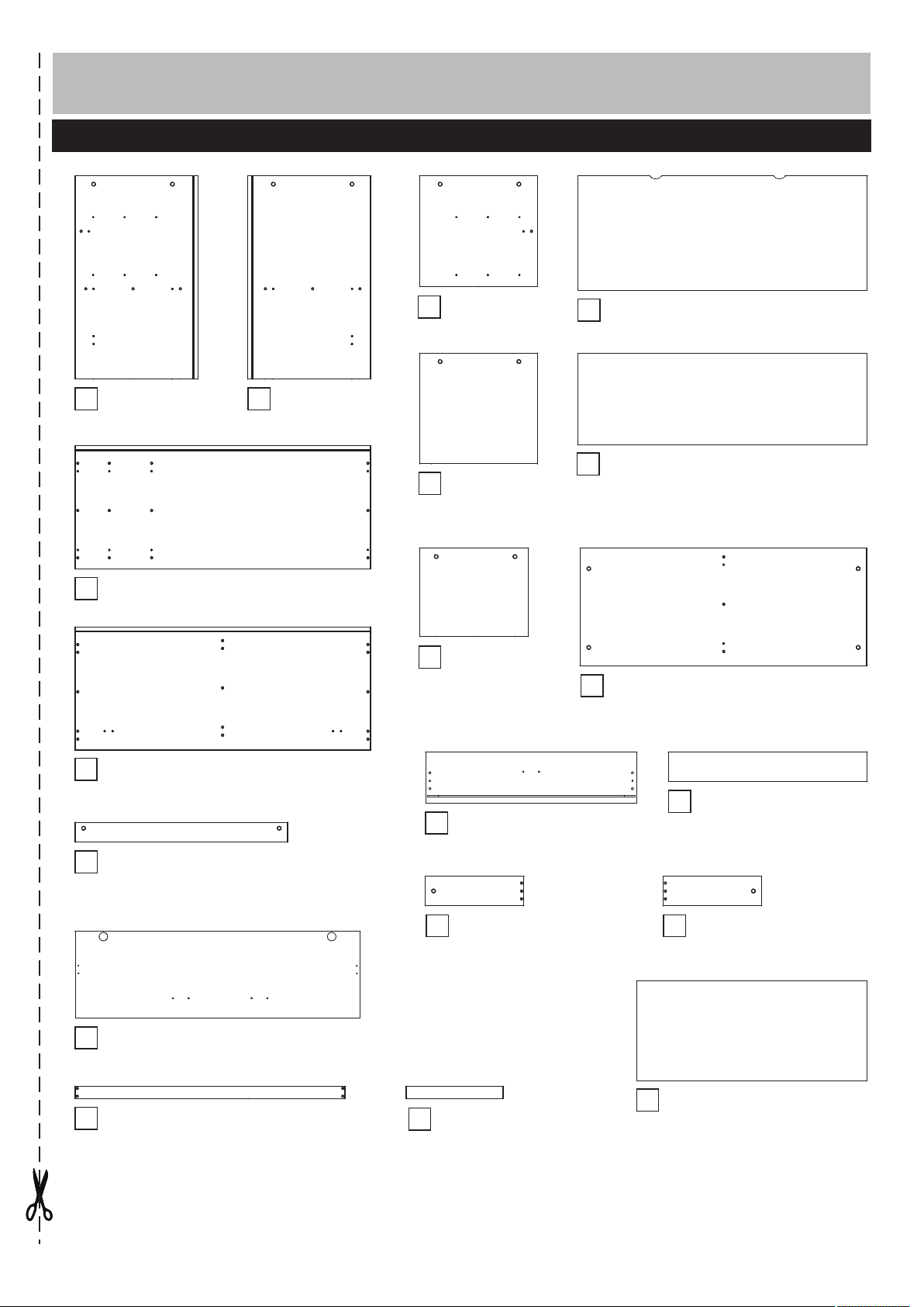
Component - Panels
call the Customer Helpline: 0845 6400 800
Please check you have all the panels listed below
Left side
1
(82.5 x 49.8cm)
Top
3
(120 x 50.0cm)
Right side
2
(82.5 x 49.8cm)
Vertical
5
partition top
(44.9 x 47.8cm)
Vertical
6
partition right
(44.9 x 47.8cm)
Vertical
7
partition
bottom
(35.8 x 44.2cm)
Rear top (117.6 x 46.5cm)
16
Rear bottom (117.6 x 37.3cm)
17
Horizontal partition
8
(116.3 x 47.8cm)
Bottom
4
(120 x 50cm)
Front support
9
(86.3 x 8cm)
Flap
10
(115.7 x 35.2cm)
Long plinth x 2
18
(109.6 x 5cm)
Drawer front x 2
11
(85.7 x 20.6cm)
Drawer left side x 2
13
(40 x 12cm)
Short plinth x 2
19
(39,4 x 5cm)
Drawer back x 2
12
(80.7 x 12cm)
Drawer right side x 2
14
(40 x 12cm)
Drawer base x 2
15
(83.8 x 40,5cm)
3
Page 4
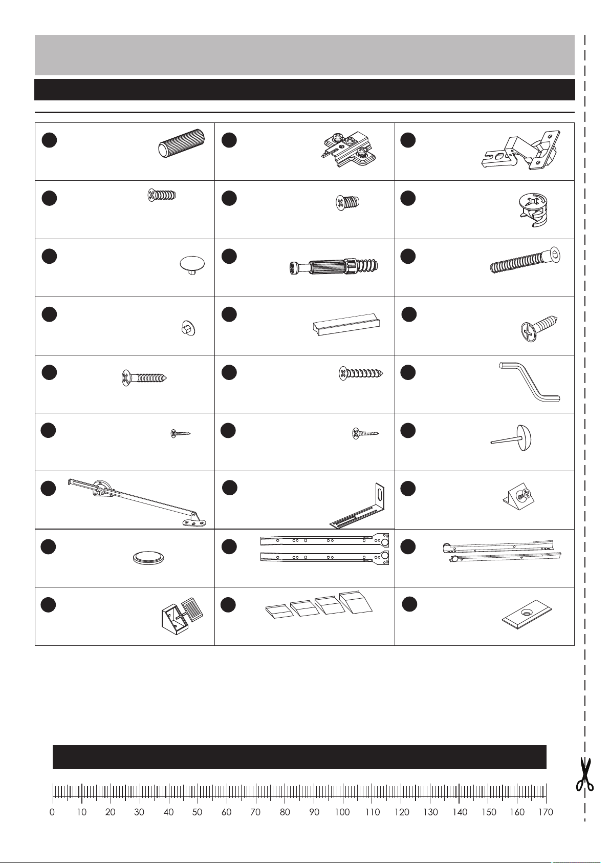
Components - Fittings
Please check you have all the fittings listed below
A
Wooden dowel x 70 (8x35) Hinge plate x 2
D E
4x13mm Screw x 4
G
Cap x 20
J
Cap bolt x 14
HM
3.5x27mm Screw x 8
P
B
5x13mm Screw x 12
H
Metal dowel x 20
K
Handle x4
N
3x20mm Screw x 12
Q
C
CC
Door hinge x 2
F
( 15x13)
I
L
4x16mm Screw x 2
O
Allen key x 1
R
Locking nut x20
(7x50) Hexagon bolt x 14
3x16mm Screw x 31
S
Flap stay x 2
V
Bumper x 1
Y
Mounting bracket x 6
3,5x16mm Screw x 18
T
Wall bracket x 2
W
Runner x 2
Z
Height adjuster x 1
Feet x 4
U
Stabilizer x 14
X
Runner x 2
U1
Washer x 5
Ruler - Use this ruler to help correctly identify the screws
4
Page 5
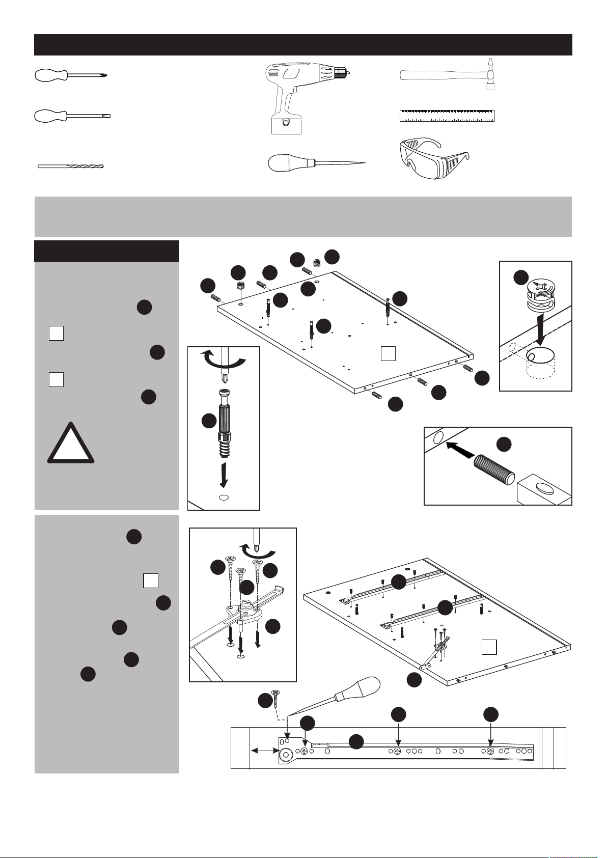
Tools required
Phillips screwdriver
(medium & large)
Flatblade screwdriver
(medium)
5 & 8mm Suitable drill bit
(for use with wall plug)
Assembly Instructions
Step 1Step 1
a:
a: Inserting dowels
and locking nuts
Insert locking nuts
into the left side panel
.
1
Insert wooden dowels
into the left side panel
.
1
Screw metal dowels .
WARNING!
Please wear
goggles or
!
protective
eyewear whilst
hammering
dowels in place.
F
H
F
A
A
H
A
H
Small
hammer
Ruler/tape
measure
Drill
0 10 20 30 40 50 60 70 80 90 100 110 120 130 140 150
0 1 2 3 4 5 6
Eye protection
(when using a
Punch
A
F
F
H
H
hammer or glue)
F
1
A
A
A
A
b: fixing runners
Position runners 38mm
from front edge
of the left side panel .
Fix runners with screws .
Mark the top left with a
punch. Screw into the
hole.
Attach flap stay using
screws .
Q
W
1
E
P
S
b:
Q
Q
P
38
Q
W
W
S
1
S
E E
E
W
5
Page 6

Assembly Instructions
Step 1Step 2
a: Inserting dowels
and locking nuts
Insert locking nuts
into the right side panel
.
2
Insert wooden dowels
into the right side panel
.
2
Screw metal dowels .
WARNING!
Please wear
goggles or
!
protective
eyewear whilst
hammering
dowels in place.
F
H
a:
A
F
A
A
A
H
F
H
H
2
A
A
F
A
A
b
flap stay usingAttach
screws .
Q
b:
S
Q
Q
S
2
Q
S
6
Page 7

Assembly Instructions
Step 1Step 2Step 1Step 3
a: Inserting dowels
and locking nuts
Insert locking nuts
into the vertical partitions
.
55667
Insert wooden dowels
into the vertical partitions
.
Screw metal dowels .
7
WARNING!
Please wear
goggles or
!
protective
eyewear whilst
hammering
dowels in place.
F
A
H
A
F
F
A
A
F
A
A
H
5
A
A
A
F
6
Finished
front edge
A
F
H
A
A
A
F
A
F
A
A
7
A
A
A
7
Page 8

Assembly Instructions
Step 1
Step 2
Step 1
Step 4
Fixing runners
from front edge
of the vertical partition
top .
5
Fix runners with screws .
Mark the top right with a
punch. Screw into the
hole.
Step 1
Step 2
Step 1
Step 5
Insert locking nuts
into the horizontal partition
.
8
Insert wooden dowels
into the horizontal partition
.
8
Screw metal dowels .
W
Position runners 40mm
E
P
F
A
H
Finished
front edge
W
5
F
F
A
H
W
P
EE
W
H
8
E
38
F
A
A
F
A
A
A
A
8
F
H
Page 9

Assembly Instructions
Step 6
a: Inserting dowels
and locking nuts
H
H
Screw metal dowels
into the top .
Attach “hinge plates"
into the bottom .
3
H
B
4
Step 7
Insert locking nuts
into the front support .
F
9
H
H
H
H
H
H
B
F
H
A
3
B
4
B
Insert wooden dowels
into the front support .
Insert wooden dowels
into the long plinth .
Repeat with the short
plinth .
19
WARNING!
Please wear
goggles or
!
protective
eyewear whilst
hammering
dowels in place.
9
A
18
A
F
A
F
9
x2
A
A
A
18
A
A
A
A
x2
19
A
A
9
Page 10

Assembly Instructions
Step 8
Fitting hinges to doors
Fix 2 hinges to the
flap using screws .
10
C
D
Step 9
a: Attaching plinth
Attach feet to the
long plinth
Attach the long plinth
to the short plinth .
!
R
18
18
19
WARNING!
Please wear
goggles or
protective
eyewear whilst
hammering
sliders in place.
a:
C
C
R
19
R
10
D
D
C
RR
18
19
R
18
b: Attaching plinth
Fit long plinth
& short plinth to the
bottom .
10
18
19
4
b:
19
18
18
4
19
Page 11

Assembly Instructions
Step 10
Mounting bracket
Place mounting
bracket onto the
assembly as shown.
Mark holes with a
punch and fix the
bracket with screws
Y
Q
Step 11
Attaching partitions
Attach vertical partition
bottom
to the horizontal partition .
7
8
YY
18
Y
19
18
YY
Y
A
F
O
H
F
Y
4
19
YY
Q
Y
Y
Q
Finished
front edge
Use the allen key to
turn locking nuts
clockwise to lock.
Use the allen key to
turn locking nuts
clockwise to lock.
Attach vertical partitions
5
6
to the horizontal partition
using hexagon bolt
& allen key .
Cover bolts with caps .
O
F
O
F
8
I
O
J
5
Finished
front edge
8
7
I
O
6
I
I
I
I
I
J
J
11
Page 12

Assembly Instructions
Step 12
Attaching panels
Attach left side panel
to the front support
& horizontal partition
Attach right side panel
to the horizontal partition .
Fix front support
to the vertical partition
top .
5
Use the allen key to
turn locking nuts
clockwise to lock.
1
9
8
2
8
9
O
F
Step 13
5
6
9
1
8
2
7
A
O
F
H
F
Attaching top
Attach top to the
sides
& vertical partitions
Use the allen key to
turn locking nuts
clockwise to lock.
3
122
5
O
F
6
3
9
1
8
7
5
6
12
Page 13

Assembly Instructions
Step 14
Inserting back
Slide back panels ,
into the grooves of
sides ,
and top .
12222
3
161717
Step 15
Attaching bottom
Attach bottom to the sides
& vertical partition bottom
using hexagon bolt
& allen key .
4
7
I
O
1
16
3
I
I
I
4
19
I
I
18
18
I
19
O
Cover bolts with caps .
J
7
22
17
1
16
3
I
J
J
I
13
Page 14

Assembly Instructions
Step 16
Fixing rear panels
Fix rear panel
to back of chest
using stabilizer .
Attach washers
using screw .
U
U1
P
U
P
U1
IMPORTANT !
Cabinet MUST
be “square”
!
when back is
attached.
U
U
U1
U
U1
U
UU
16
U1
U
U1
17
U
U
U1
U
U
14
Page 15

Assembly Instructions
Step 17
Fixing to wall
It is recommended that
the sideboard is fixed to
a wall.
T
With help, move
sideboard into position.
Mark fixing hole on wall
and remove sideboard .
Drill holes on the marking
on the wall.
Install wall bracket
to the wall.
Reposition sideboard.
Fix sideboard to wall
brackets with screw .
Place a spirit level on
bottom .
Where necessary, insert
height adjuster to
make bottom level.
Cover cams with caps .
4
TTT
L
Z
4
G
L
T
T
3
6
5
2
9
1
8
7
4
Z
G
15
Page 16

Assembly Instructions
Step 18
Drawer assembly
a: drawer back:
Insert wooden dowels
into the drawer back .
b: Insert 2 locking nuts
into the drawer sides &
14
. Insert wooden
dowels into the
drawer sides .
A
WARNING!
Please wear
goggles or
!
protective
eyewear whilst
hammering
dowels in place.
A
12
F
13
a:
A
x2
F
x2
12
A
A
A
A
A
A
A
b:
13
A
F
14
x2
A
F
c: Screw metal dowels
into the drawer front .
d:Fix drawer sides
&
14
13
to drawer the back using
hexagon bolt .
Cover bolts with caps .
I
H
12
13
J
c:
d:
13
H
H
H
11
x2
14
12
I
O
I
I
J
I
J
16
Page 17

Assembly Instructions
Step 19
Drawer assembly
a: Attach drawer front
to the drawer sides.
Use the allen key to
turn locking nuts
clockwise to lock.
Cover cams with caps .
b: Attach drawer base
using screws &
stabilizer . U
O
S
11
O
F
G
16
a:
b:
13
15
11
A
F
15
14
O
H
F
x2
G
U
IMPORTANT!
Drawer MUST
!
c: Attach runner using
screws .
Repeat step 19 & 20 for all
drawers.
be “square”
when base is
attached.
X
N
c:
H
N
U
U
P
P
15
P
P
P
12
P
P
x2
X
H
N
X
X
X
15
12
x2
17
Page 18

Assembly Instructions
Step 20
Hanging flap
a: slot flap hinges onto
‘hinge plates’.
b: Tighten screw
shown to lock hinges in
position.
Insert drawers to the
cabinet.
Fix flap stay to
the flap
using screws .
10
C
S
P
a:
B
b:
B
Hinge adjustment
H
M
C
H
M
K
C
11
Attach bumper onto the
vertical partition bottom .
Attach door handles
using screws .
Assembly is complete.
H
M
V
7
K
H
M
K
2
V
7
H
M
H
H
M
K
M
K
P
S
1
11
4
10
P
S
If you need help or have damaged or missing parts, call the Customer Helpline: 0845 6400 800
18
Page 19

 Loading...