

Page 1
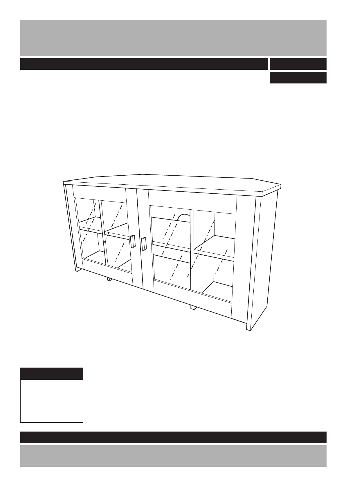
Chequer Corner TV Unit
Assembly Instructions
-
Please keep for future reference
609/2452
609/2469
Dimensions
Width - 100cm
Depth - 40.3cm
Height - 49.2cm
Important - Please read these instructions fully before starting assembly
If you need help or have damaged or missing parts, call the
Customer Helpline: 08456 400800
Version 2
Date: 8/07/10
Page 2

Safety and Care Advice
Important - Please read these instructions fully before starting assembly
• Check you have all the
components and tools listed on
pages 2 and 3.
rom the
plastic bags and separate them
into their groups.
• Keep children and animals away
from the work area, small parts
could choke if swallowed.
• Make sure you have enough
space to layout the parts before
starting.
• Do not stand on the product,
this could cause damage.
• Assemble the item as close to
room) as possible.
• Assemble on a soft level surface
to avoid damaging the unit or your
r.
• Parts of the assembly will be
easier with 2 people.
as this could damage the unit.
Only use hand screwdrivers.
• Dispose of all packaging
carefully and responsibly.
• Note: Only apply the glue once
you are sure of the assembly.
Glue safety - Take care when using glue, please follow the advice below
Skin contact: Remove
contamination by washing with
soap and water. This procedure
should also be followed prior to
eating and drinking.
Eye contact: Rinse immediately
with clean water for 15 minutes
and seek medical advice.
If swallowed: Seek medical
advice immediately.
• We do not
recommend the
use of power
drill/drivers for
inserting screws,
Care and maintenance
• Only clean using a damp cloth
and mild detergent, do no use
bleach or abrasive cleaners.
• From time to time check that
there are no loose screws on
this unit.
Keep these instructions for future reference
• This product complies with
BSEN14749:2005
• Model / Catalogue Number:
609/2452, 609/2469
• Retailer : Argos Ltd. MK9 2NW
• If a glass component is
chipped or broken, stop using
the product and consult the
manufacturer or supplier.
1
Warning
• Do not place very hot or very
cold items against or in close
proximity to glass surfaces
unless an adequately thick
insulating material is used to
prevent such items from coming
into contact with the glass.
• This product should not be
discarded with household
Take to your local authority
disposal centre.
• Do not strike the glass with
hard or pointed items.
• When cleaning glass panels
use a damp cloth or leather with
washing up liqed or soft if
necessary; do not use washing
powders or any other substances
containing adrasives since these
substances scratch glass.
Note: if required the next
page can be cut out and used
as reference throughout the
assembly. Keep this page with
these instructions for future
reference.
Page 3
If you have damaged or missing components,
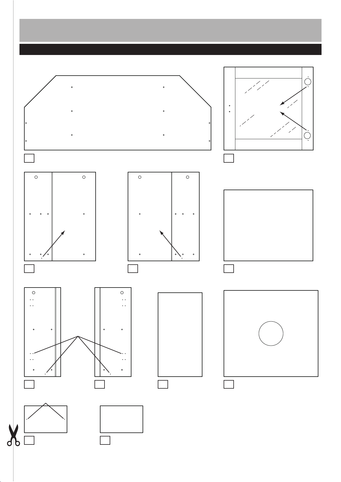
Components - Panels
call the Customer Helpline: 08456 400800
Please check you have all the panels listed below
Pilot holes for
guidance only
Table top panel (100 x 40cm)
1
Pilot holes for
guidance only
Middle left panel
3
(38.1 x 47.6cm)
Pilot holes for
guidance only
Middle right panel
4
(38.1 x 47.6cm)
Door x 2
2
Middle support x 2
5
(47.6 x 38cm)
(48 x 44.5cm)
Pilot holes for
guidance only
Left side panel
6
(19.5 x 47.6cm)
Pilot holes for guidance only
Bottom panel x 2
10
(23 x 14.4cm)
Right side panel
7
(19.5 x 47.6cm)
Shelf panel x 2
11
(23 x 14.4cm)
Small back panel
8
x 2 (23.7 x 44.5cm)
Large back panel
9
(46 x 50.3cm)
2
Page 4
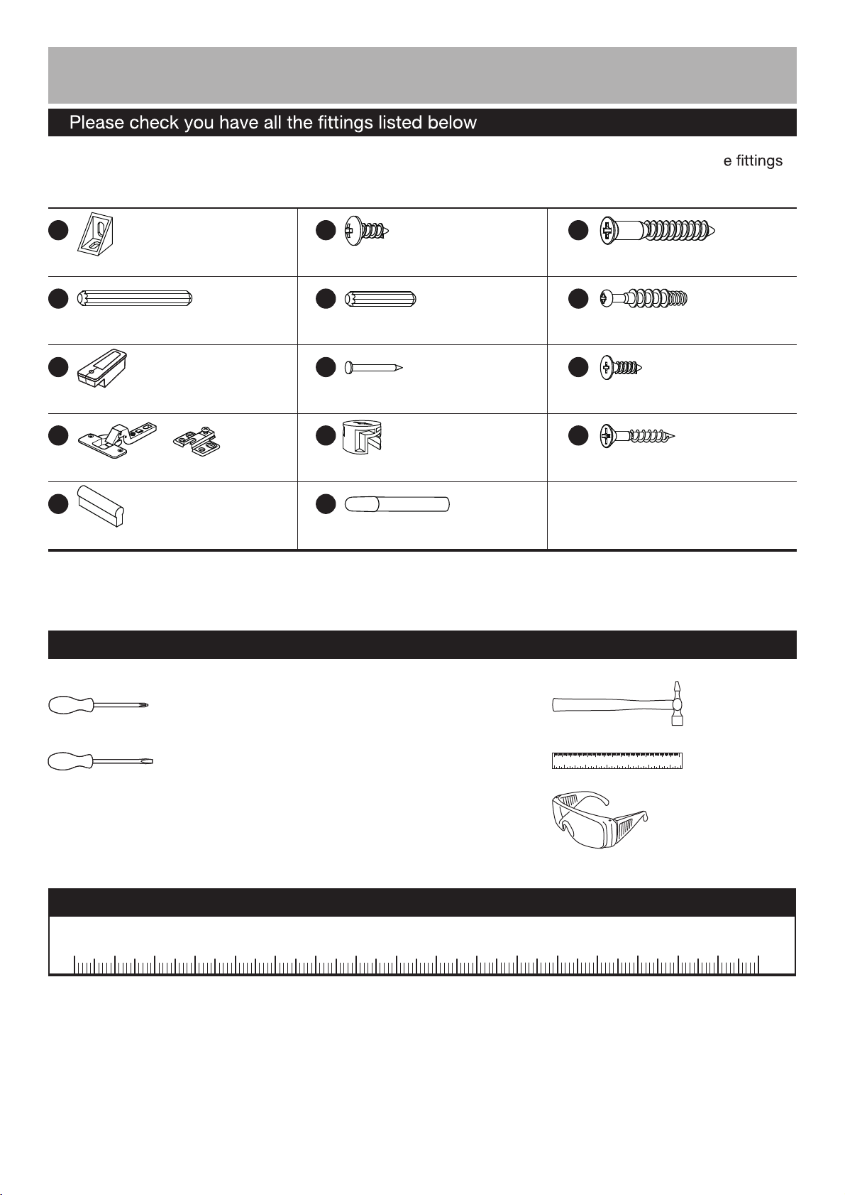
Components - Fittings
Note: The quantities below are the correct amount to complete the assembly. in some cases mor
may be supplied than are required.
A
B
C
Plastic support x 4 14mm Screw x 8 50mm Screw x 8
D
E
F
Longe wooden dowel x 8 Short wooden dowel x 12 Locking pin x 6
G
H
I
(Screws are included in
the Door hinge bag)
Nail guide x 1 Nail x 14 15mm Screw x 24
J
K
L
Door hinge x 4 15mm Locking nut x 6 25mm Screw x 4
M
N
Handle x 2 Glue x 1
Tools required
Phillips screwdriver
(medium & large)
Flatblade screwdriver
(medium)
Ruler - Use this ruler to help correctly identify the screws
0 5 10 15 20 25 30 35 40 45 50 55 60 65 70 75 80 85 90 95 100
105
Small
hammer
0 1 2 3 4 5 6
110 120 130 140 1500 10 20 30 40 50 60 70 80 90 100
Ruler/tape
measure
Eye protection
(when using a
hammer or glue)
110 115 120 125 130 135 140 145 150 155 160 165 170
3
Page 5
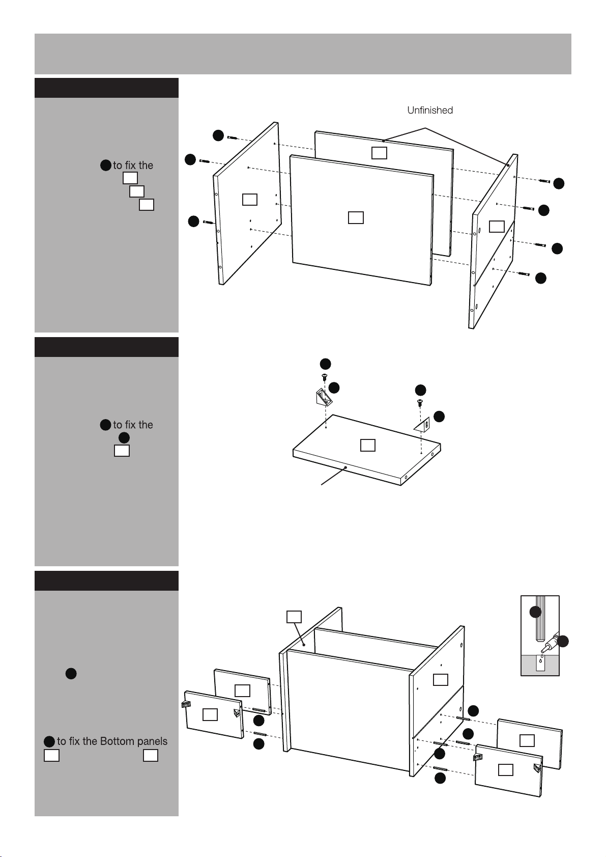
Assembly Instructions
Step 1
Attaching middle
supports
Use Screws
Middle left panel and
Middle right panel onto
the Middle supports .
C
3
4
5
Step 2
Attaching plastic
supports
Use Screws
Plastic supports onto the
Bottom panels .
B
A
10
back edge
C
C
3
C
B
A
5
C
C
5
4
C
C
B
A
10
Step 3
Attaching bottom and
shelf panels
Place a small amount of
N
Gule into the dowel holes
and onto the joint’s
surfaces.
Use Long wooden dowels
D
10
and Shelf panels
onto the unit.
11
10
11
Finished
front edge
4
D
D
x 2
3
D
D
D
D
N
D
11
10
4
Page 6

Assembly Instructions
Step 4
Attaching hinges
I
Door hinges ‘back
J
plates’onto the Left and
Right side panel & .
7
6
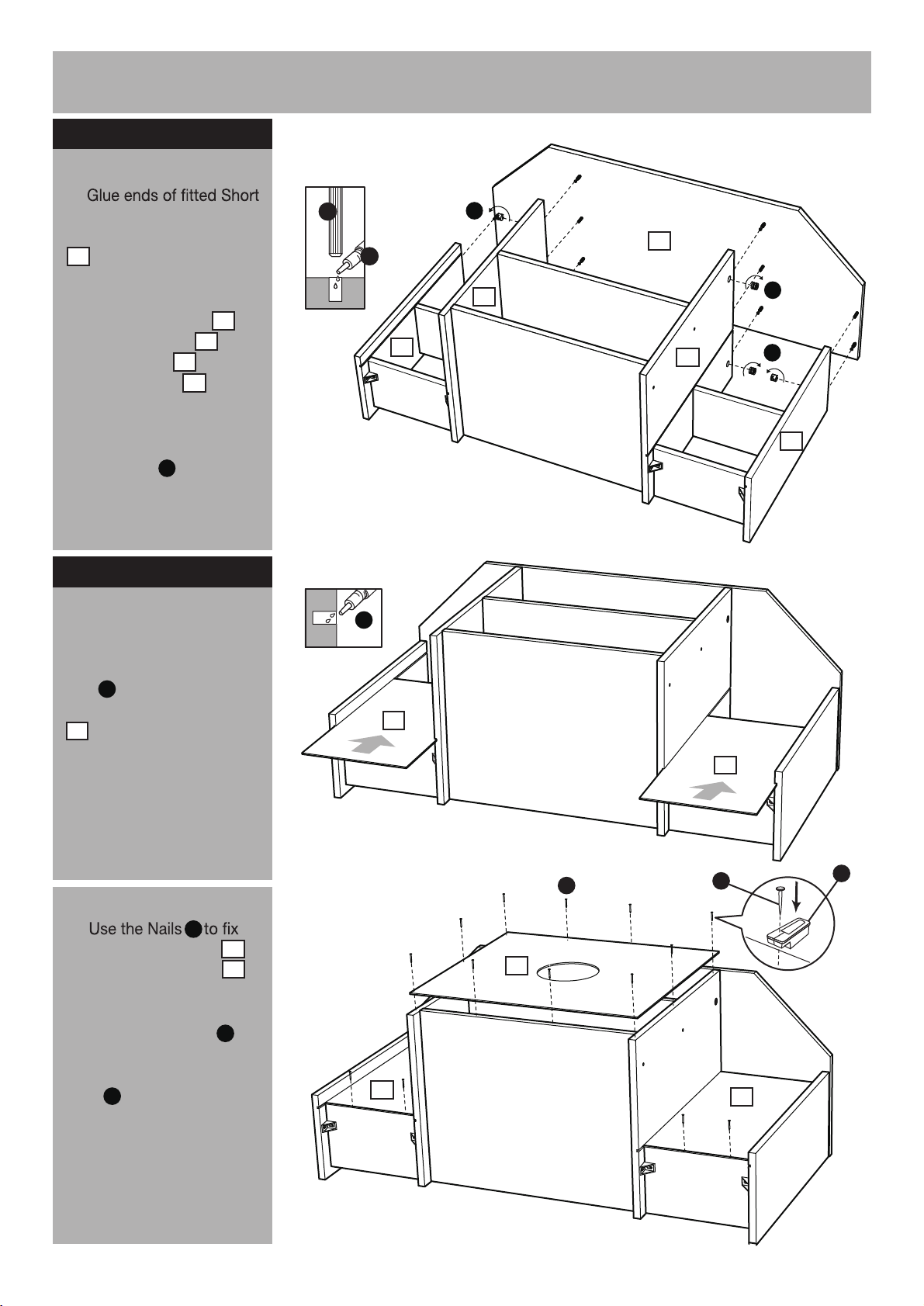
Step 5
Attaching side panels
Place a small amount of
N
Gule into the dowel holes.
Use Short wooden dowels
and Screws
E
Left side panel and
Right side panel onto
the unit.
B
6
7
J
7
E
E
I
Front
I
J
6
I
J
I
J
I
J
7
Front
E
N
E
B
B
E
E
E
6
Step 6
Attaching table top
panel
a:
Place a small amount of
Glue into the dowel
N
holes of the Table top
panel .
Screw in Locking pins
and insert Short wooden
dowels into the Table top
panel .
Note:
as far as shown.
Do not over tighten.
1
F
E
1
Insert Locking pins
Continued on next page.
a:
F
E
F
E
N
E
F
F
E
Finished
front edge
F
E
F
E
1
F
5
Page 7
Assembly Instructions
Step 6 - continued
b:
b:
wooden dowels. Carefully
place the Table top panel
1
onto the unit.
Insert 6 Locking nuts into
the Middle left panel ,
Middle right panel ,
Left side panel and
Right side panel
3
4
6
7
where shown.
Use a screwdriver to turn
Locking nuts clockwise
K
to lock.
Step 7
Attaching back panels
a:
E
N
7
N
K
1
4
3
K
K
6
a:
Place a small amount of
N
Glue into the groove.
Slide the Small back panels
into the unit.
8
b:
the Small back panels
and Large back panel
H
8
9
onto the unit.
Note:
Use Nail guide
G
to keep a constant
distance from the edge to
Nails .
H
b:
8
8
H
9
8
H
8
G
6
Page 8

Assembly Instructions
Step 8
Attaching hinges
Fix two Door hinges
to each Doors using
Screws .
Attach the Handles to the
outside of the Doors
using Screws .
I
J
2
M
2
L
Step 9
M
J
I
2
J
L
I
I
J
I
2
J
L
I
J
M
Hanging doors
a:
With help, slot Door
hinges onto ‘hinge
J
plates’.
b:
Tighten screw shown to
lock hinges in position.
Repeat
a and b for
opposite door.
See ‘Hinge adjustment
’
in step 9 if the doors need
adjusting.
a:
J
J
J
b:
J
J
J
7
Page 9

Assembly Instructions
Step 10
a:
Hinge adjustment
a:
To move doors up or
down: loosen screws
shown and move doors to
suit.
Once doors are aligned,
re-tighten and insert
Screws into all ‘hinge
plates’.
I
I
b:
To move doors in or
out: loosen screw shown
and move doors to suit.
Re-tighten screws.
c:
To move doors left or
right: loosen screw shown
and move doors to suit.
Re-tighten screws.
b:
c:
Assembly is complete.
If you need help or have damaged or missing parts, call the Customer Helpline: 08456 400800
8
 Loading...