

Page 1
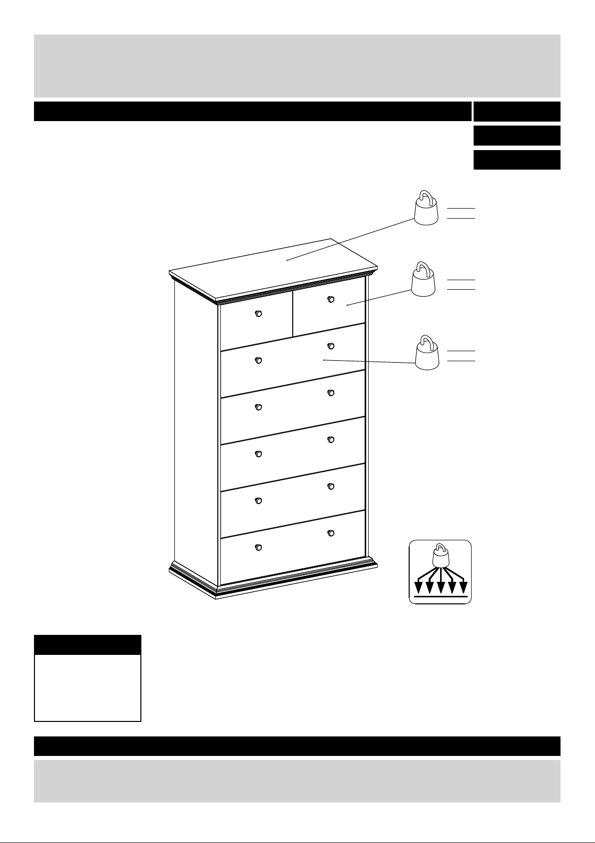
Canterbury 5+2 CHEST
Assembly Instructions - Please keep for future reference
517/0571
509/4334
476/9086
25 Kg
55 lbs
5 Kg
11 lbs
9 Kg
20 lbs
max
Dimensions
Width - 84.3cm
Depth - 41.9cm
Height - 144.5cm
Important – Please read these instructions fully before starting assembly
If you need help or have damaged or missing parts, call the Customer Helpline:
Argos = 0845 6400800
71932 Version E Date 10/02/2016
Page 2
Safety and Care Advice
Important – Please read these instructions fully before starting assembly
• Check you have all the
components and tools listed on
the following pages.
• Remove all fi ttings from the
plastic bags and separate them
into their groups.
• Keep children and animals
away from the work area, small
parts could choke if swallowed.
• Make sure you have enough
space to lay out the parts before
starting.
• During assembly, do not stand
or put weight on the product,
this could cause damage.
• Assemble the item as close
to its fi nal position (in the same
room) as possible.
• Assemble on a soft level
surface to avoid damaging the
unit or your fl oor.
• Parts of the assembly will be
easier with 2 people.
the unit. Only use hand screw
drivers.
Glue safety - Take care when using glue, please follow the advice below
Skin contact: Remove
contamination by washing with
soap and water. This procedure
should also be followed prior to
eating and drinking.
Eye contact: Rinse immediately
with clean water for 15 minutes
and seek medical advice.
If swallowed: Seek medical
advice immediately.
• We do not
recommend the use
of power drivers for
inserting screws, as
this could damage
Care and maintenance
• Only clean using a damp cloth
and mild detergent, do no use
bleach or abrasive cleaners.
Safety
• The provided tip-over restraint
must be installed in order to
optimize user safety.
• From time to time check that
there are no loose screws on
this unit.
• This product should not be
discarded with household waste.
Take to your local authority
waste disposal centre.
Note: if required the next
page can be cut out and used
as reference throughout the
assembly. Keep this page with
these instructions for future
reference.
1
Page 3
If you have damaged or missing components, call the
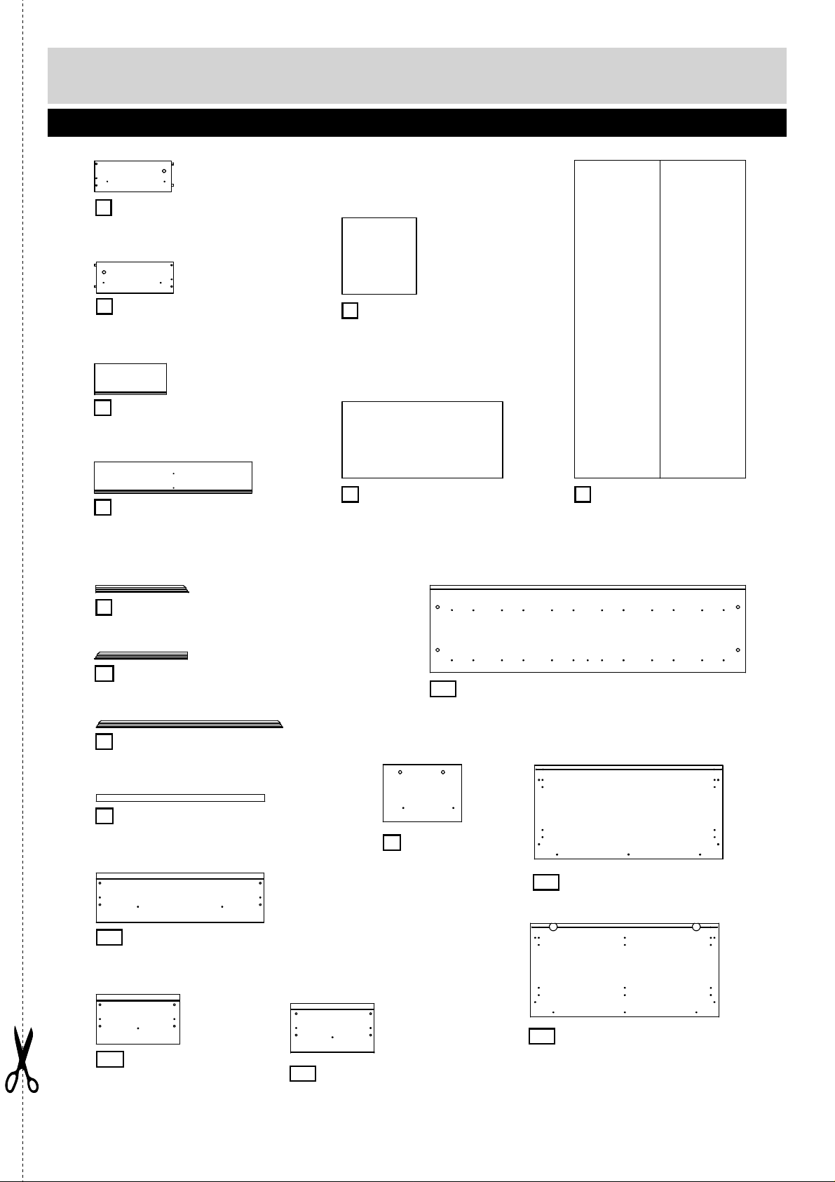
Components - Panels
Customer Helpline: Argos = 0845 6400800
Please check you have all the panels listed below
A 00489 Left drawer side
(34.5 x 14cm) x7
B 00488 Right drawer side
(34.5 x 14cm ) x7
C 02743 Drawer back
( 32.1 x 14cm) x2
D 02744 Drawer back
(70.6 x 14cm) x5
K 76425 Profile side
(41.5 x 2.5cm) x2
M 76426 Profile side
(41.5 x 2.5cm) x2
P 06056 Drawer bottom
(33.3 x 34.2cm) x2
R 06057 Drawer bottom
(71.8 x 34.2cm) x5
FY Side panel L/R
(141.2 x 39 cm) x2
S 09783 Back panel
(142.1 x 76.4cm)
N 76315 Profile front
(83.5 x 2.5 cm) x2
O 76316 Base rail
(75.4 x 3.1 cm)
EE Drawer front
(75.1 x 22.1cm) x5
EG
Drawer front, left
(37.4 x 22.1cm)
G
(25.6 x 35.2 cm)
EF
Drawer front, right
(37.4 x 22.1cm)
Divider panel
IA Bottom panel (84.3 x 41.9cm)
LA Top panel (84.3 x 41.9cm)
2
Page 4
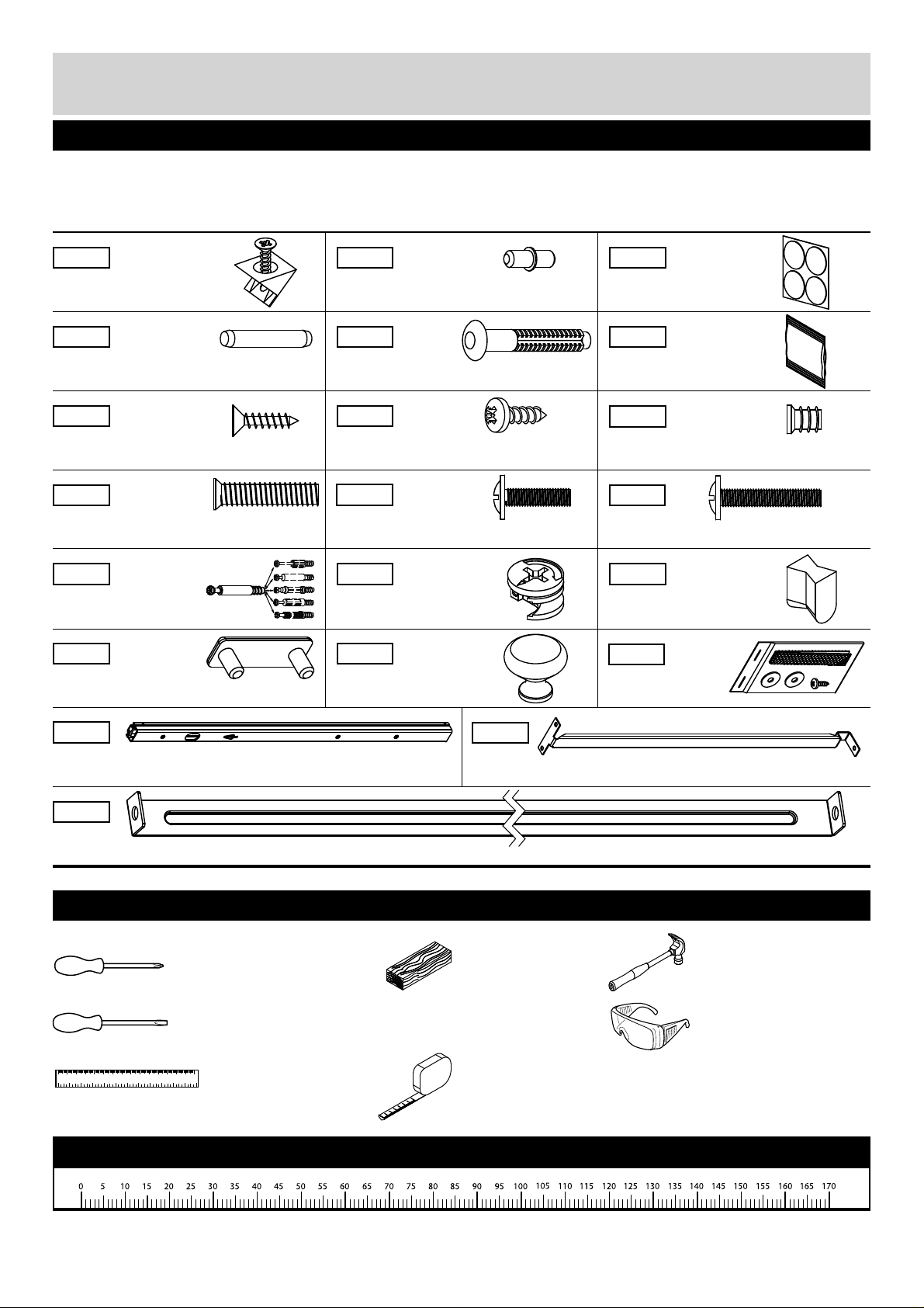
Components - Fittings
Please check you have all the fi ttings listed below
Note: The quantities below are the correct amount to complete the assembly. In some cases more fi ttings
may be supplied than are required.
10401 11011
Panel clips x8
20203 20228 22601
Dowel (ø5 x 30mm) x17
25233 25440
Flat head screw (ø3,5 x 15mm) x14
26033
Flat head screw (ø6,3 x 27mm) x7
31513
Cam bolt x24
63008
Floor glider x4
Drawer support x14
Drawer fastener x28
Screw (ø4 x 13mm) x15
26221
Machine screw (M4 x 15mm) x28
31687 33204
Cam x24
81040
Handle x12
17414
Tape dots x1
Glue x1
26020
Flat head screw (ø5,8 x 9mm) x30
26232
Machine screw (M4 x 23mm) x12
Wedges x4
94009
Strap x2
41435
Drawer runner x14
94066
Stabilizer x1
10510
Drawer bottom support x5
Tools required
Cross head screwdriver
(medium & large)
Flathead screwdriver
(medium)
01 02 03 04 05 06 07 08 09 0 100 110 120 130 140 150
01 23 45 6
Ruler
Wooden block
Tape measure
Ruler - Use this ruler to help correctly identify the screws
Hammer
Eye protection
(when using a
hammer or glue)
3
Page 5
Assembly Instructions
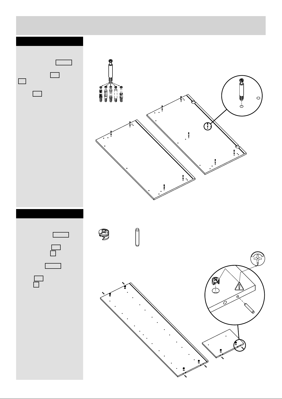
Step 1
Fittings you will need for this step:
Insert cam bolts
Insert cam bolts 31513
into the holes on top and
bottom panel LA and
IA . Also insert cam bolts
in center holes of the top
panel LA . See detail
drawing.
Cam bolt
# 31513 X10
Cam bolt must be
screwed fl ush down.
Step 2
Insert dowles
Insert dowels 20203 into
outer holes on the ends
of side panel FY and
divider panel G .
IA
Fittings you will need for this step:
Cam
# 31687 X10
Dowel
# 20203 X10
LA
Place cam 31687 into
the holes on top of side
panel FY and divider
panel G .
Arrow facing the edge of
the panel.
FY
(X2)
G
5
4
Page 6
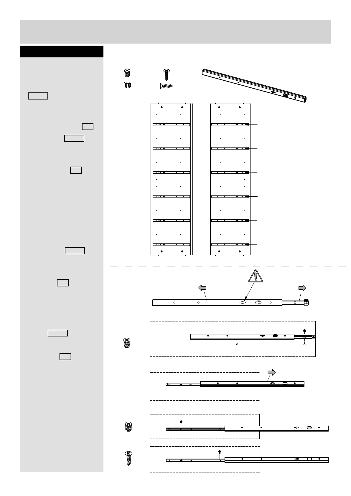
Assembly Instructions
Step 3
Place drawer runners
1.
Extend drawer glide
41435 .
2.
Attach drawer glide at the
front of side panel FY .
Place screw 26020
through the correct hole
at the front of the drawer
glide, into the holes on
the side panel FY .
Tighten screw but do not
overtighten.
3.
Fittings you will need for this step:
Flat head screw
# 26020 X24
FY
Flat head screw
# 25233 X12
Drawer runner
# 41435 X12
FY
12
10
8
5
Open slide until holes
are visible at back of
drawer glide.
4.
Place screw 26020
through the correct holes
at the back of the drawer
glide, into the holes on
the panel FY .
Tighten screw but do not
overtighten.
5.
Attach the fl at head
screw 25233 into the
correct holes of the
drawer glide, into the
side panel FY .
Tighten screw but do not
overtighten.
1.
2.
3.
x1
Front
Front
3
1
Front
Repeat these 5 steps for
the remaining runners.
6
5
Front
4.
x1
5.
x1
Page 7

Assembly Instructions
Step 4
Place drawer runners
1.
Extend drawer glide
41435 .
2.
Attach drawer glide at the
front of divider panel G .
Place screw 26020
through the correct hole
at the front of the drawer
glide, into the holes on
divider panel G .
Tighten screw but do not
overtighten.
3.
Open slide until holes
are visible at back of
drawer glide.
Fittings you will need for this step:
Drawer runner
# # 41435 X2
G
Flat head screw
# 26020 X4
Flat head screw
# 25233 X2
Front
4.
Place screw 26020
through the correct holes
at the back of the drawer
glide, into the holes on
divider panel G .
Tighten screw but do not
overtighten.
5.
Attach the fl at head
screw 25233 into the
correct holes of the
drawer glide, into divider
panel G .
Tighten screw but do not
overtighten.
Repeat these 5 steps for
the remaining runner on
the other side of divider
panel G .
7
6
Page 8

Assembly Instructions
Step 5
Attaching bottom panel
Place cam bolts from the
bottom panel IA into
the holes in the end of
side panels FY .
Make sure the fi nished
edge is facing toward
the front and that the
unfi nished side is facing
toward the bottom of the
cabinet.
Tighten the cams.
19,4 cm
9,8 cm
Front
IA
Front
FY
FY
7
7
Page 9

Assembly Instructions
Step 6
Attaching back panel
Slide the back panel S
smoothly down into the
grooves in the side and
bottom panel FY + IA .
S
FY
FY
IA
Step 7
Attaching divider panel
Press down divider panel
G towards the top panel
LA . Make sure the
fi nished edge is facing
toward the front .
Tighten cams with a
screwdriver, as shown.
G
LA
Unfi nish face
8
Page 10

Assembly Instructions
Step 8
Attaching top panel
Place the cam bolts from
top panel LA into the
end holes on side panel
FY . Tighten cams.
FY
LA
G
FY
S
9,8 cm
Step 9
Gathering profi les
Insert wedges 33204
into slots on the angle
ends of side and front
profi les K + N + M .
Use a hammer.
IA
Fittings you will need for this step:
Wedges
# 33204 X4
Top
Bottom
M
N
x2
K
9
Page 11

Assembly Instructions
Step 10
Fittings you will need for this step:
Gathering profi les to
cabinet
Push the profi le down
as it reaches the bottom
panel IA . Use fl at head
screw 26033 to tighten.
Flat head screw
# 26033 X7
LA
G
FY
FY
S
IA
Step 11
Gathering profi les
Insert dowels 20203
into outer holes on the
gathering profi les. Use
glue 22601 as shown.
Add one small drop of
glue per hole.
Fittings you will need for this step:
Dowel
# 20203 X7
N
K
Glue
# 22601 X1
M
max 9 mm
10
Page 12

Assembly Instructions
Step 12
Fittings you will need for this step:
Gathering profi les to
cabinet
Glue
# 22601 X1
Add glue 22601 in holes
of the top panel LA .
Add one small drop of
glue per hole.
Place the gathering
profi le as shown and
press down (dowels into
holes).
FY
IA
FY
S
G
LA
Step 13
Attaching tape dots
Attack the tape dots
17414 at the base rail
O .
Fittings you will need for this step:
Tape dots
#17414 X1
O
11
Page 13

Assembly Instructions
Step 14
Attaching base rail
LA
Turn cabinet around
standing on bottom
panel IA .
Take off paper from tape
dots.
Place the base rail O
behind the gathering
profi le (push forward as
shown with the arrow).
O
FY
S
IA
G
FY
Step 15
Attaching stabilizer
Place the stabilizer
94066 between the two
side panels FY . See
the detail drawing, for
correct direction. Use the
fl at head screw 26020
to tighten the stabilizer.
O
Fittings you will need for this step:
Flat head screw
# 26020 X2
FY
LA
Stabilizer
# 94066 X1
FY
S
IA
12
Page 14

Assembly Instructions
Step 16
Fittings you will need for this step:
Attaching back panels
Important:
The unit MUST
be square when
the panel clips is
attached.
Lay face down the
cabinet on the fl oor. To
stabilize the back panel,
use the panel clips
10401 . Press forward
the thin tabs between
the back panel and the
groove.
Then tighten with a
screwdriver.
Panel clips
# 10401 X8
Step 17
Attaching gliders
Place the fl oor gliders
63008 in the holes of
bottom panel IA .
Use a wodden block
between hammer and
fl oor glider.
FY
Fittings you will need for this step:
Floor Glider
# 63008 X4
S
IA
13
FY
S
IA
Page 15

Assembly Instructions
Step 18
Fittings you will need for this step:
Fix unit to wall with
strap
The screw supplied
together with the
anti-topple bracket
is to be used only
for fi xing the
anti-topple bracket
to the furniture. In
addition to this you
will need to choose
a screw or fi tting
which is suitable
for securing the
bracket to the kind
of wall you have.
If you are unsure
about what type
of screw to use
contact your local
hardware store.
Strap
# 94009 X2
94009
LA
3 cm
FY
FY
IA
14
Page 16

Assembly Instructions
Step 19
Fittings you will need for this step:
Attaching drawers
Attach cam 31687 into
the holes in left and
right drawer side A + B .
Arrow facing the edge of
the panel.
Screw the cam bolt
31513 in the drawer
front EF + EG + EE .
Cam bolts must be
screwed down fl ush.
Cam
# 31687 X14
Cam bolt
# 31513 X14
B
(x2)
A
(x2)
(x2)
EE
(x5)
B
(x2)
A
15
14
EF/EG
(x2)
Page 17

Assembly Instructions
Step 20
Fittings you will need for this step:
Attaching drawer
Align holes at back of
the drawer sides A +
B with the holes on the
drawer back D and C .
Screw
# 20228 X28
A
B
A
C
Make sure the groove
is facing inside of the
drawer.
Tap drawer fasteners
20228 into place with a
hammer.
Step 21
Attaching drawer
bottom
x2
B
D
x5
Press the drawer bottom
R and P smoothly in
the grooves (fi nished
side up).
A
P
B
A
R
B
D
x5
C
x2
16
15
Page 18

Assembly Instructions
Step 22
Attaching drawer front
Attach the drawer front
EE and EF + EG by
placing dowels and cam
bolt in the correct holes.
See the detail drawing.
Tighten the cams.
EE
EF/EG
A
P
A
R
B
C
x2
Step 23
Attaching the drawer
Attach the handle 81040
to the drawer front EE
and EF + EG . Use
machine screw 26232 to
tighten the handle.
Attach the drawer support
11011 into holes on left
and right drawer side A
+ B .
B
Fittings you will need for this step:
Handle
# 81040 X12
Machine screw
# 26232 X12
D
Drawer support
# 11011 X14
EE
R
x5
EF/EG
A
P
A
C
B
x2
17
16
D
B
x5
Page 19

Assembly Instructions
Step 24
Fittings you will need for this step:
Attaching drawer
bottom support
Place the drawer bottom
support 10510 on back
side of the drawers. See
the detail drawing, for
correct direction. Use the
screw 25440 to tighten
the drawer bottom support.
Drawer bottom support
# 10510 X5
R
Screw
# 25440 X15
Step 25
Pulling out the rails
Pull out all the runners,
before placing drawers.
A
D
x5
LA
G
FY
S
FY
IA
18
17
Page 20

Assembly Instructions
Step 26
Fittings you will need for this step:
Attaching the drawers
1.
Place the drawer
between 2 rails.
See picture.
Machine screw
# 26221 X28
EG EF
EE
EE
EE
2.
Adjust front of drawer
up and down. Tight up
and fi x drawer to the rail
useing machine screw
26221 from inside the
drawer in both sides.
3.
Adjust back of drawer
up and down. Tight up
and fi x drawer to the rail
useing machine screw
26221 from inside the
drawer in both sides.
Repeat these step for each
of the remaining drawers.
EE
EE
1.
Drawer back
2.
x2
3.
x2
Assembly is complete.
If you need help or have damaged or missing parts, call the Customer Helpline:
Argos = 0845 6400800
19
Drawer front
Drawer back
18
 Loading...