

Page 1
MADE IN
BRITAIN
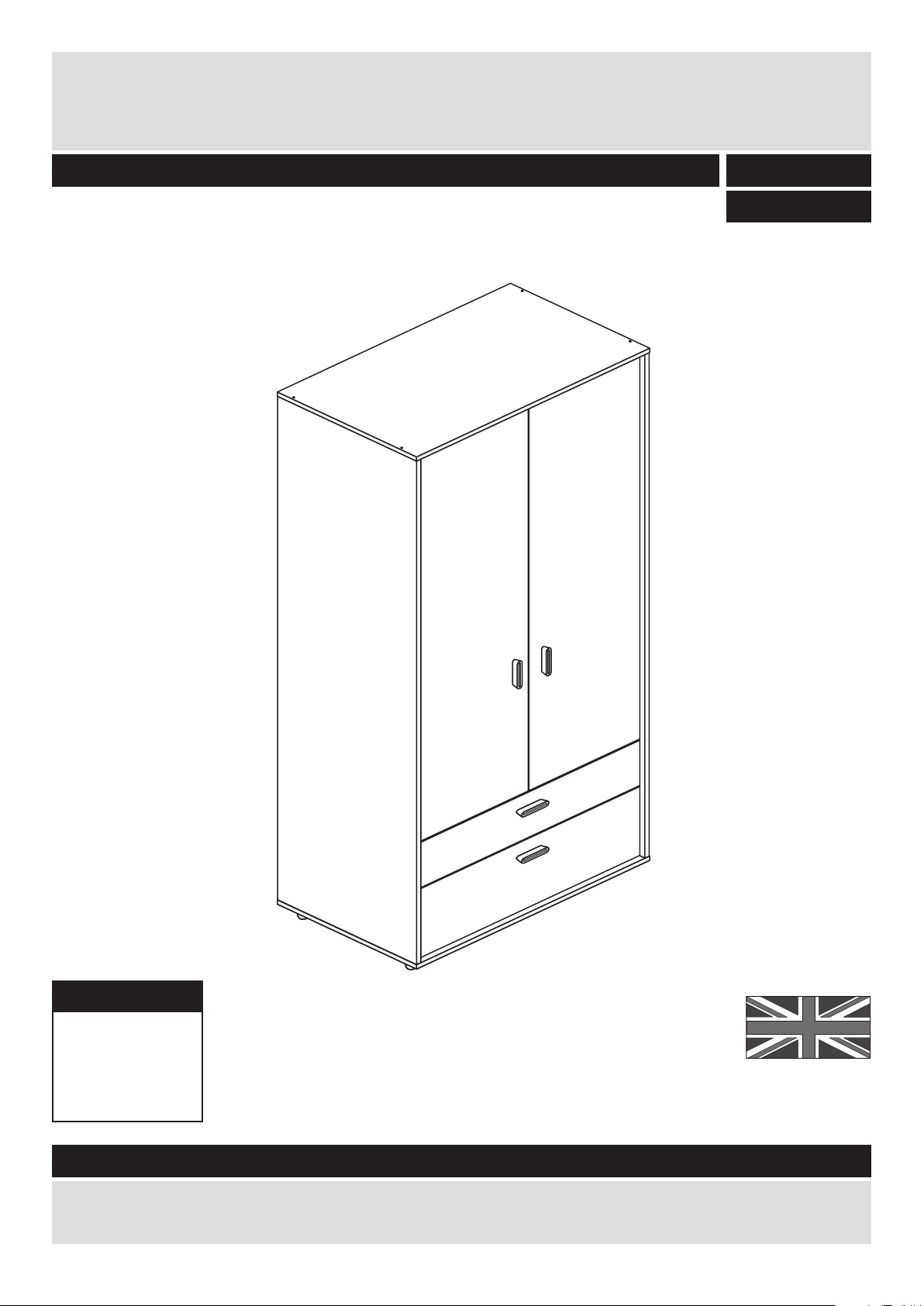
Dimensions
Width - 83cm
Depth - 49.5cm
Height - 186.5cm
Arvika - 2 Drawer 2 Door Robe
Assembly Instructions - Please keep for future reference
If you need help or have damaged or missing parts, call the Customer Helpline: 08456 400800
Issue 2 - 16/12/14
Important - Please read these instructions fully before starting assembly
357/6823
356/4921
Page 2
Safety and Care Advice
Important - Please read these instructions fully before starting assembly
• Warning: This unit weighs
approximately 52.5kgs.
Please lift with care.
• Check you have all the
components and tools listed on
pages 2 and 3.
• Remove all fittings from the
plastic bags and separate them
into their groups.
• Keep children and animals
away from the work area, small
parts could choke if swallowed.
• Parts of the assembly will be
easier with 2 people.
• Make sure you have enough
space to layout the parts before
starting.
• Do not stand or put weight on
the product, this could cause
damage.
• Assemble the item as close to
its final position (in the same
room) as possible.
• Assemble on a soft level
surface to avoid damaging the
unit or your floor (use opened
out unit carton).
1
Care and maintenance
• Only clean using a damp cloth
and mild detergent, do no use
bleach or abrasive cleaners.
• From time to time check that
there are no loose screws on
this unit.
• This product should not be
discarded with household
waste. Take to your local
authority waste disposal centre.
Note: If required the next page
can be cut out and used as
reference throughout the
assembly. Keep this page with
these instructions for future
reference.
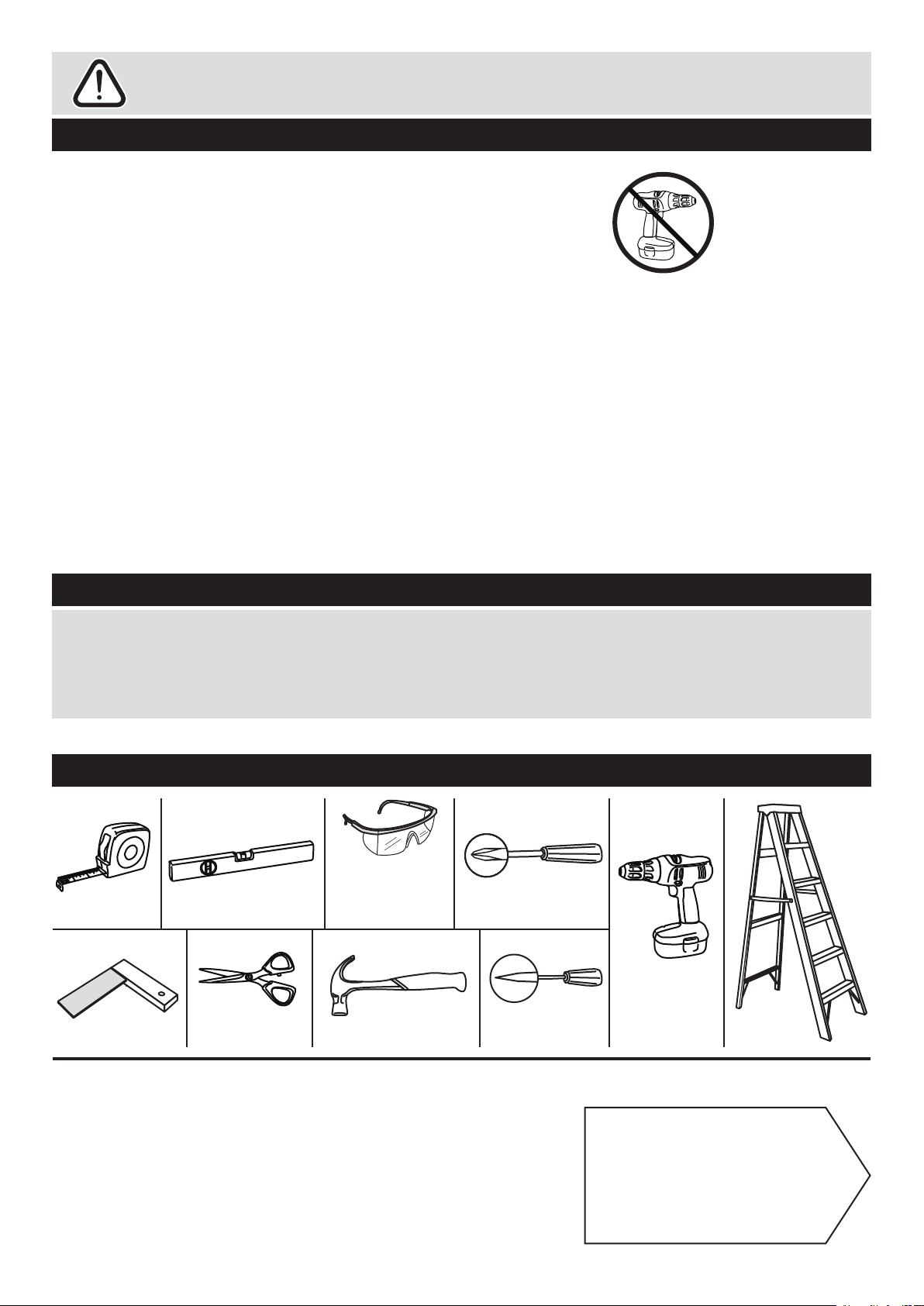
• We do not
recommend the
use of power
drill/drivers for
inserting screws,
as this could damage the unit.
Only use hand screwdrivers.
• Safety note: It is
recommended that this unit is
secured to a wall using the
overbalance kit supplied.
• Dispose of all packaging
carefully and responsibly.
Rule
Tools required
Rule
ScissorsSquare
Spirit
level
Hammer Bradawl
Eye protection
(when using a
hammer or drill)
Cross-head
screwdriver
Step
ladder
Electric drill
(only use
when drilling
into walls)
Page 3
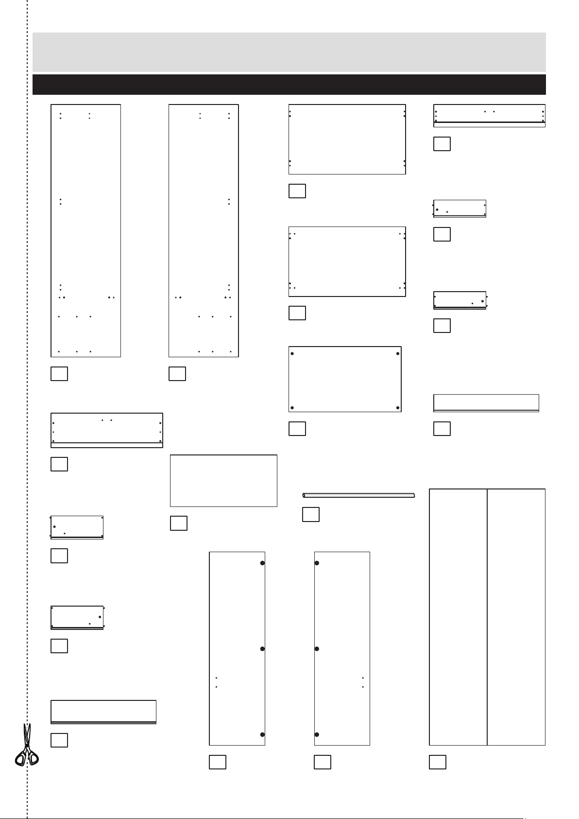
Components - Panels
Please check you have all the panels listed below
2
1
2
4
If you have damaged or missing components, call the
Customer Helpline: 08456 400800 quoting the reference
numbers below
Left Side (DF1888)
(1791 x 494mm)
Top (DF919)
(829 x 495mm)
Right Side (DF1889)
(1791 x 494mm)
3
Base (DF1966)
(829 x 495mm)
Horizontal (DF1420)
(797 x 464mm)
Top Drawer
Front (DF1886)
(791 x 161mm)
Top Drawer
Back (W746-124)
(746 x 124mm)
Top Left Drawer
Side (W370-124LH)
(370 x 124mm)
Top Right Drawer
Side (W370-124RH)
(370 x 124mm)
Bottom Drawer
Front (DF1887)
(791 x 245mm)
Bottom Drawer
Back (W746-165)
(746 x 165mm)
Bottom Left Drawer
Side (W370-165LH)
(370 x 165mm)
Bottom Right Drawer
Side (W370-165RH)
(370 x 165mm)
5
6
7
8
9
10
11
12
13
14
Back (X1817-888)
(1817 x 822mm)
1716 18
Hanging Rail (FHR791)
(791mm long)
15
Drawer Base (T757-367)
(757 x 367mm) x 2
Right Door (DF1890)
(1371 x 394mm)
Left Door (DF3023)
(1371 x 394mm)
Page 4
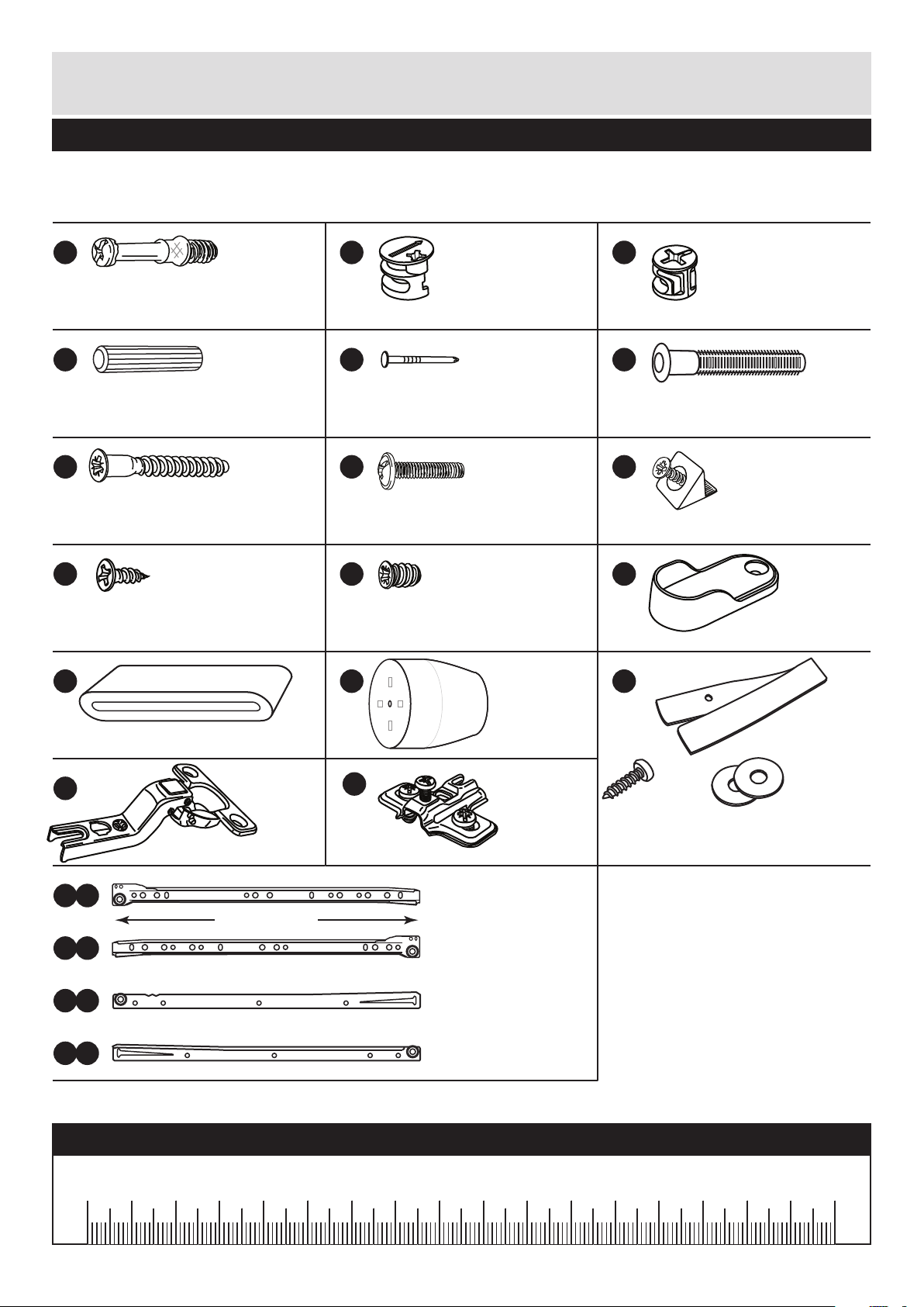
Please check you have all the fittings listed below
3
Components - Fittings
If you have damaged or missing components, call the
Customer Helpline: 08456 400800 quoting the reference
numbers below
Note: The quantities below are the correct amount to complete the assembly. In some cases
more fittings may be supplied than are required.
Ruler - Use this ruler to help correctly identify the screws
mm 10 20 30 40 50 60 70 80 90 100 110 120 130 140 150 160 170
A B
D E F
G H I
L
Small locking
nut (F3) x 4
C
Nail (F51) x 34
40mm Screw (F910) x 12
J K
N
Knock-in Peg (F171GY) x 8
Large locking
nut (F900) x 4
Metal dowel (F901) x 8
Wooden dowel (F22) x 12
M
P
Wedgefix (F639) x 8
19mm Screw (F461) x 8
13mm Screw (F63) x 28
9mm Screw (F73) x 12
Handle (F336) x 4
Leg (F334) x 4
R
R Runner (F160) x 2
b
L Runner (F161) x 2
R
c
L Runner (F159) x 2
R
a
R Runner (F162) x 2
R
d
350mm long
Rail Holder
(F891) x 2
Q
Hinge plate
(F523) x 6
Hinge (F522) x 6
O
Strap
Screw Washer x 2
Overbalance protector kit (F269) x 1
Page 5
6
Assembly Instructions
4
If you have damaged or missing components, call the
Customer Helpline: 08456 400800 quoting the reference
numbers below
Step 1
A
B
A
C
C
C
C
7
8
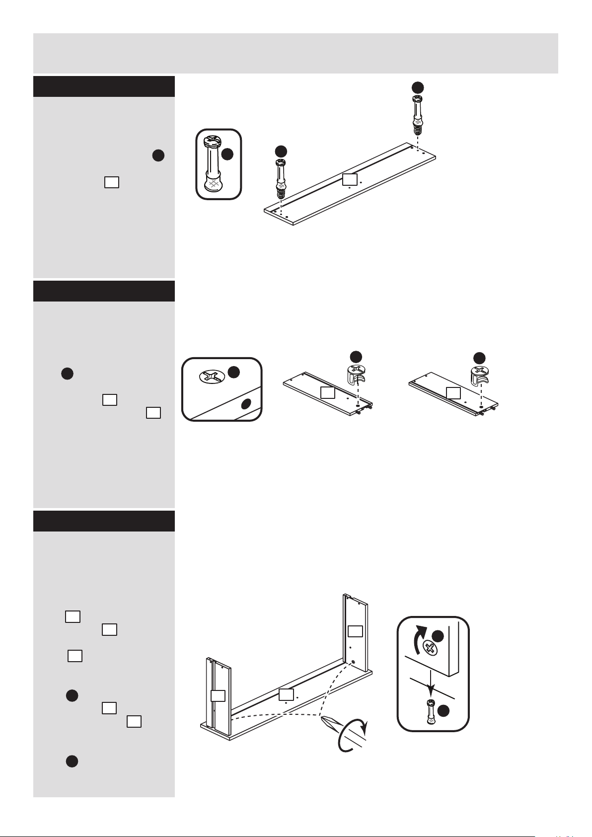
Step 2
Prepare the top
drawer front
Screw 2 metal dowels
into the back of the top
drawer front .
Note: Tighten the metal
dowels up fully against
the panels.
A
6
Prepare the top
drawer sides
Insert a small locking
nut into the hole
shown on the top left
drawer side and the
top right drawer side .
Note: The arrow on the
locking nut must point
towards the hole in the
edge of the panel.
Step 3
C
7
8
Attach the top drawer
sides to the top
drawer front
Push the top left drawer
side and top right
drawer side onto the
back of the top drawer
front .
Turn the small locking
nuts on the top left
drawer side and top
right drawer side .
Note: Turn the locking
nuts clockwise to
secure panels - more
than 1/2 a turn.
7
8
6
C
C
7
8
A
A
6
7
8
Page 6
6
Assembly Instructions
5
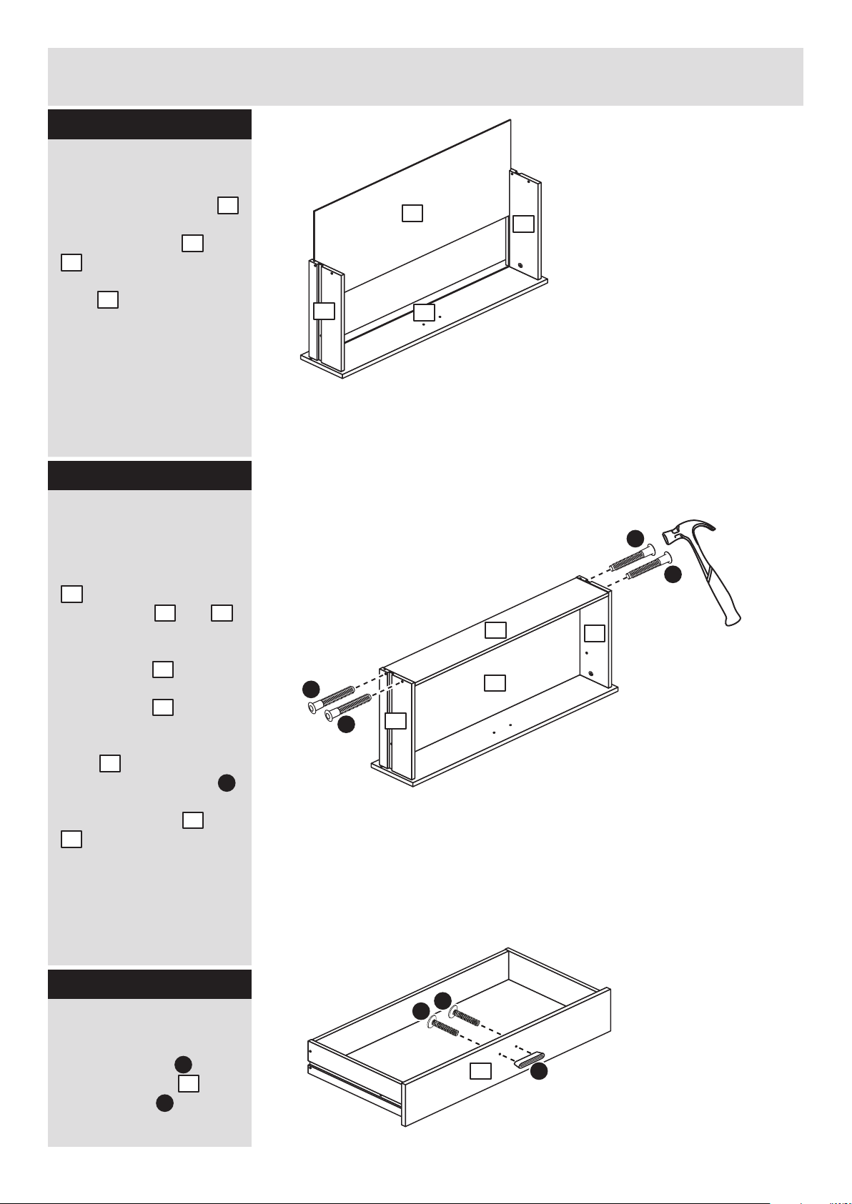
Step 4
F
F
Fit the drawer base
Slide the drawer base
down the grooves in the
top drawer sides and
. and down into the
groove in the top drawer
front .
Step 5
Fit the top drawer
back
Fit the top drawer back
. between the top
drawer sides and .
Make sure that the
drawer base fits into
the groove in the top
drawer back .
Hold the top drawer
back in position and
tap the knock-in pegs
through the holes in the
top drawer sides and
. .
Step 6
14
7
8
6
9
7 8
14
9
9
F
F
F
8
7
14
8
7
7
8
14
9
Attach the handle
Attach a handle to the
top drawer front
using screws .
H
6
M
M
H
H
6
Page 7

R d
R
R
Assembly Instructions
6
Step 7
I
Fit the wedgefixes
Turn the top drawer
assembly over and slide
4 wedgefixes into the
front and back grooves,
as shown, and tighten up
the screws.
I
I
I
I
I
Fit the runners
Fit a runner ,
marked with ‘R’, to the
bottom edge of the top
right drawer side , as
shown, making sure that
it is pushed up against
the back of the top
drawer front . Use a
bradawl to mark the
fixing positions, then
secure with 2 screws .
Fit runner , marked
‘L’, to the bottom edge
of the top left drawer
side using the same
method.
7
R d
8
6
J
R c
Step 8
J
J
J
J
8
7
6
L
R c
L
Runners must be
pushed up against
the drawer front
Page 8

10
Assembly Instructions
7
Step 9
A
B
A
C
C
C
C
11
12
Step 10
Prepare the bottom
drawer front
Screw 2 metal dowels
into the bottom drawer
front .
Note: Tighten the metal
dowels up fully against
the panels.
A
10
Prepare the bottom
drawer sides
Insert a small locking
nut into the hole
shown on the bottom left
drawer side and the
bottom right drawer side
. .
Note: The arrow on the
locking nut must point
towards the hole in the
edge of the panel.
Step 11
C
11
12
Attach the bottom
drawer sides to the
bottom drawer front
Push the bottom left
drawer sides and
bottom right drawer
sides onto the back
of the bottom drawer
front .
Turn the small locking
nuts on the bottom
left drawer side and
bottom right drawer side
. .
Note: Turn the locking
nuts clockwise to
secure panels - more
than 1/2 a turn.
11
12
10
C
C
11
12
12
11
10
A
A
Page 9

10
Assembly Instructions
8
Step 12
F
F
12
Fit the drawer base
Slide the drawer base
down the grooves in the
bottom drawer sides
and and down into
the groove in the bottom
drawer front .
Step 13
Step 14
14
11
12
10
14
11
12
11
Fit the bottom drawer
back
Fit the bottom drawer
back between the
bottom drawer sides
and .
Make sure that the
drawer base fits into
the groove in the bottom
drawer back .
Hold the bottom drawer
back in position and
tap the knock-in pegs
through the holes in the
bottom drawer sides
and .
13
11
12
14
13
13
F
11
12
F
F
14
13
Attach the handle
Attach a handle to the
bottom drawer front
using screws .
H
10
M
H
H
10
M
Page 10

Assembly Instructions
9
Step 15
Fit the runners
Fit a runner ,
marked with ‘R’, to the
bottom edge of the
bottom right drawer side
. , as shown, making
sure that it is pushed up
against the back of the
bottom drawer front .
Use a bradawl to mark
the fixing positions, then
secure with 2 screws .
Fit runner , marked
‘L’, to the bottom edge
of the bottom left drawer
side using the same
method.
11
R d
12
10
J
R c
Step 16
I
Fit the wedgefixes
Turn the bottom drawer
assembly over and slide
4 wedgefixes into the
front and back grooves,
as shown, and tighten up
the screws.
I
I
I
I
I
R d
R
R
J
J
J
J
L
R c
L
Runners must be
pushed up against
the drawer front
11
12
10
Page 11

Finished
front edge
Finished
front edge
Finished
front edge
D
D
Assembly Instructions
10
Step 17
Q
R b
K K
1st
screw
2nd
screw
K
3rd
screw
Finished
front edge
Prepare the left side
a: Fit 2 runners to
the left side .
The 1st screw uses
the 1st hole in from the
front of the runners.
The 2nd and 3rd screws
. use the holes that line
up with the other panel
holes.
b: Fit a screw into
the 2nd hole in at the top
of the runners .
Screw 2 metal dowels
into the left side .
To fit the rail holder ,
screw through the top
hole with screw and
into the mark hole drilled
in the left side . Make
sure that it is fitted
straight, in line with the
panel edges and then fit
another screw using
the lower hole.
c: Tap 4 wooden
. dowels into the left
side .
Note: Wooden dowels
must not stick out from
the edge by more than
10mm or they may
damage other panels.
Fit 3 hinge plates onto
the left side , making
sure that the slot is
facing towards the
finished front edge.
R b
1
K
K
J
R b
10mm
D
K
R b
K
K
J
J
K
R b
K
K
Q
Q
Q
A
A
J
L
L
J
J
L
D
D
L
J
J
1
1
A
D
1
Q
1
J
1
1
1
a:
b:
c:
Page 12

D
D
Assembly Instructions
Step 18
Prepare the right side
a: Fit 2 runners to
the right side .
The 1st screw uses
the 1st hole in from the
front of the runners.
The 2nd and 3rd screws
. use the holes that line
up with the other panel
holes.
b: Fit a screw into
the 2nd hole in at the top
of the runners .
Screw 2 metal dowels
into the right side .
To fit the rail holder ,
screw through the top
hole with screw and
into the mark hole drilled
in the right side .
Make sure that it is fitted
straight, in line with the
panel edges and then fit
another screw using
the lower hole.
c: Tap 4 wooden
. dowels into the right
side .
Fit 3 hinge plates onto
the right side , making
sure that the slot is
facing towards the
finished front edge.
R b
2
K
K
J
R b
L
J
J
2
2
A
D
2
Q
2
P b
J
R b
KK
1st
screw
2nd
screw
K
3rd
screw
Finished
front edge
K
K
R b
K
K
K
R b
K
2
Finished
front edge
2
J
J
J
J
L
A
A
Finished
front edge
2
Q
Q
Q
Q
D
D
a:
b:
c:
11
Page 13

Finished
front edge
Finished
front edge
Finished
front edge
D
D
D
Assembly Instructions
12
Step 19
B
B
B
B
D
B
Prepare the horizontal
Insert 4 large locking
nuts into the
horizontal .
Note: The arrow on the
locking nut must point
towards the hole in the
edge of the panel.
Tap 4 wooden dowels
into the horizontal .
B
D
5
5
Fit the right side to
the horizontal
Push the horizontal
onto the right side .
Use a screwdriver to
tighten the 2 large
locking nuts fitted to
the horizontal .
Note: Turn the large
locking nuts as far as
they will go - more than
1/2 a turn.
2
5
B
B
Step 20
5
Fit the left side
Push the left side
onto the horizontal .
Use a screwdriver to
tighten the 2 large
locking nuts fitted to
the horizontal .
1
5
B
Step 21
5
2
5
A
B
5
1
Finished
front edge
5
Page 14

Assembly Instructions
Step 22
13
Finished
front edge
G
G
G
Fit the top
Attach the top to the
left side and right
side using 4 screws .
G
G
3
1
2
3
1
2
Note: The top panel
has been finished on
both surfaces.
The base panel only
has 1 finished suface.
Step 23
1
2
G
G
G
G
Fit the base
Attach the base to
the left side and right
side using 4 screws .
G
4
1
2
Finished
front edge
plain
chipboard
surface
4
Page 15

yy
xx
yy
Assembly Instructions
14
Step 24
Step 25
1
2
4
b:
Fit the back
a: Square up the unit by
making sure that
measurement x to x
equals y to y.
b: Place the back
onto the unit.
Nail around the
outside edges of the
back .
Note: Nails should be
spaced about 150mm
apart.
Carefully stand the
unit up for the next
step.
18
E
The measurement from top corner X to bottom corner X must be
equal to the measurement from top corner Y to bottom corner Y
a:
18
xx
E
18
Warning: The
unit is heavy.
Lift with care.
Fit the feet
Attach the 4 feet to
the base using 4
screws .
N
G
4
N
N
N
N
G
Page 16

Assembly Instructions
Step 26
15
Fit the drawers and
hanging rail
Push the hanging rail
into the rail holders .
Slide the wheels of the
runners fitted to the
drawers, over the wheels
of the runners fitted to
the side panels and push
the drawers into position.
Prepare the 2 doors
Push fit 3 hinges into
each of the 2 doors
and .
Secure each hinge with
2 screws .
Note: Before securing
with the screws, make
sure that the hinges are
positioned at 90 degrees
with the edge of the
door.
J
P
16
17
90
P
Step 27
Side
panel
Drawer
15
L
15
L
P
J
J
P
J
J
P
J
J
P
J
J
P
J
J
P
J
J
17
16
Page 17

Assembly Instructions
16
Step 28
Fit doors and handles
Note: The easiest way to
attach each door and
. is to fit the top hinge
first, then align and fit the
other hinges.
a: Push the hinge
onto the front part of the
hinge plate .
The recess at the bottom
of screw B goes into the
slot in the hinge plate.
b: Keep the hinge
FLAT against the hinge
plate as you slide it
across as far as it will go.
Tighten screw A.
c: The hinge must be
flat against the hinge
plate prior to any
adjustment.
d: The hinge must
NOT be AT AN ANGLE
to the hinge plate
when assembled.
This would indicate that
the recess at the bottom
of screw B had not
located in the slot in the
hinge plate and the hinge
would not be secure.
Remove the hinge from
the hinge plate and then
re-assemble being
careful to follow
instructions a-c.
e: Attach a handle to
each door and
using screws .
P
P
P
Q
Q
Q
P
Q
M
H
16
17
16 17
a: b:
c: d:
Q
P
Q
Q
B
Q
P
P
P
A
P
Q
B
e:
H
H
M
17
16
M
Page 18

Assembly Instructions
Step 29
b:
c:
d:
a:
Adjust the doors if
needed
a: Before adjusting the
doors, use a spirit level
to check the base (or
top) of the unit is level,
front-to-back and
side-to-side in the 3
positions shown.
Use suitable packing
pieces (not supplied) to
make the unit level
BEFORE making any
adjustment to the hinges,
as shown.
b: Height adjustment.
Loosen screws A on
hinge plates and move
door up or down as
required.
Retighten screw A.
c: Forward and Back
adjustment.
Loosen screw B on hinge
plate and move door in
or out as required.
Retighten screw B.
d: Sideways
adjustment.
To move door ‘out’
loosen screw C.
To move door ‘in’ tighten
screw C.
A
A
B
C
17
Page 19

Assembly Instructions
18
If you need help or have damaged or missing parts, call the Customer Helpline: 08456 400800
and quote the reference numbers on the component pages.
Argos Ltd, 489-499 Avebury Boulevard, Central Milton Keynes, MK9 2NW
Step 30
Fit the overbalance
protector
To prevent possible
overbalancing we
recommend that this unit
is secured to a suitable
wall by use of the
overbalance protector kit
. fitted to the unit or, an
alternative fixing method
of your choice.
Wall fixings are not
supplied as they will
need to suit the wall
type.
Note: Take care when
drilling the wall that you
do not drill into any
pipes, wires etc.
If in doubt, consult an
expert.
Assembly is complete
O
O
WALL
Wall fixing
(not supplied)
Screw
(not supplied)
Washer
Strap
O
Strap
Washer
Screw
TOP OF UNIT
O
Page 20

ALR3115
 Loading...