

Page 1
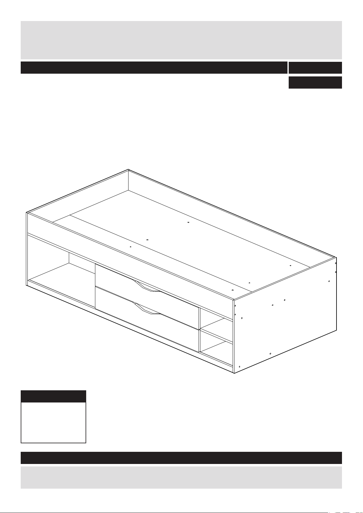
Shelby - Cabin Bed
Assembly Instructions - Please keep for future reference
322/0296
338/9663
Dimensions
Width - 195cm
Depth - 95.5cm
Height - 53cm
Important – Please read these instructions fully before starting assembly
If you need help or have damaged or missing parts, call the Customer Helpline: 0345 6400800
Issue 1 - 9/02/10
Page 2

Safety and Care Advice
Important – Please read these instructions fully before starting assembly
• Check you have all the
components and tools listed on
pages 2, 3 and 4.
• Remove all ttings from the
plastic bags and separate them
into their groups.
• Keep children and animals
away from the work area, small
parts could choke if swallowed.
• Make sure you have enough
space to layout the parts before
starting.
Care and maintenance
• Only clean using a damp cloth
and mild detergent, do no use
bleach or abrasive cleaners.
• Do not stand or put weight on
the product, this could cause
damage.
• Assemble the item as close
to its nal position (in the same
room) as possible.
• Assemble on a soft level
surface to avoid damaging the
unit or your oor.
• Parts of the assembly will be
easier with 2 people.
• From time to time check that
there are no loose screws on
this unit.
• To reduce
the likelihood of
damaging your
product please
ensure that your
power drill is set on a low torque
setting.
• Dispose of all packaging
carefully and responsibly.
• This product should not be
discarded with household waste.
Take to your local authority
waste disposal centre.
Handy Hints
• Assemble all parts and bolts
loosely during assembly, only
once the product is complete
should you fully tighten the bolts
• Regularly check and ensure
that all bolts and ttings are
tightend properly.
• WARNING: Do not place this child`s bed near heat
sources, windows and other furniture.
• WARNING: Do not use this child`s bed if any part is
broken, torn or missing.
• WARNING: Not suitable for children under the age of
4 years.
Note: if required the next
page can be cut out and used
as reference throughout the
assembly. Keep this page with
these instructions for future
reference.
1
Page 3
If you have damaged or missing components,
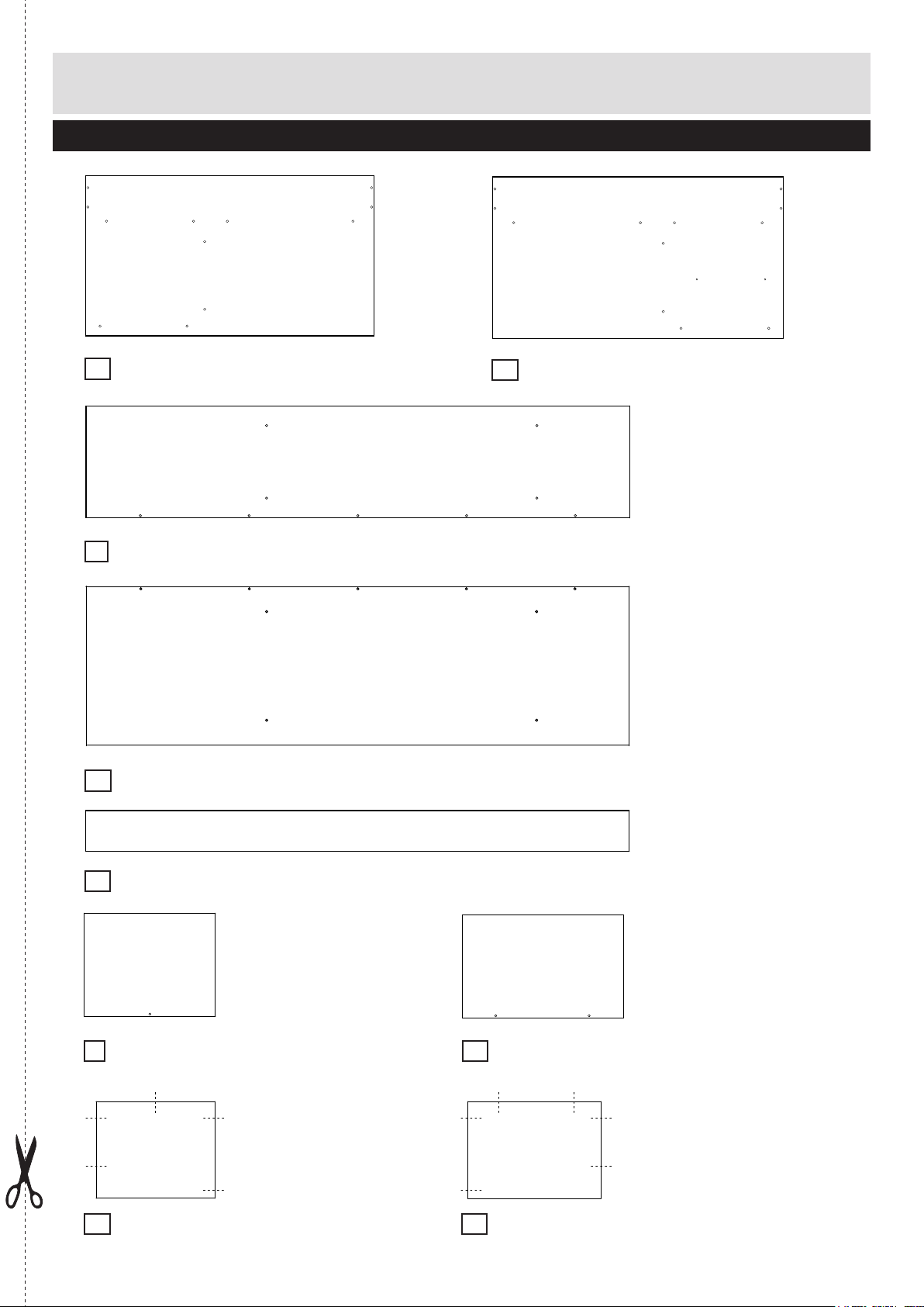
Components - Panels
call the Customer Helpline:
Please check you have all the panels listed below
Left side panel (95.5 x 53cm)
1
2
0345 6400800
Right side panel (95.5 x 53cm)
Front bed board (192 x 39.45cm)
3
Back bed board (192 x 56.05cm)
4
Front/Back bed supports x2 (192 x 14.3cm)
5
Right central support (32 x 37.2cm)
6
Right bottom panel (32 x 37.2cm)
8
Left central support (63 x 37.2cm)
7
Left bottom panel (63 x 37.2cm)
9
2
Page 4

If you have damaged or missing components,
Components - Panels
call the Customer Helpline:
Please check you have all the panels listed below
0345 6400800
Middle crossbar (94 x 12cm)
10
Front crossbar (94 x 10cm)
12
Left shelf partition (94 x 37.2cm)
13
Back crossbar (94 x 10cm)
11
Right shelf partition (94 x 37.2cm)
14
Shelf (32 x 37.2cm)
15
Front board (192 x 4cm)
17
Drawer sides x2 (159.5 x 12cm)
18
Drawer bottom panel x2 (90.3 x 33.9cm)
19
Drawer front x2 (96.9 x 16cm)
16
3
Page 5
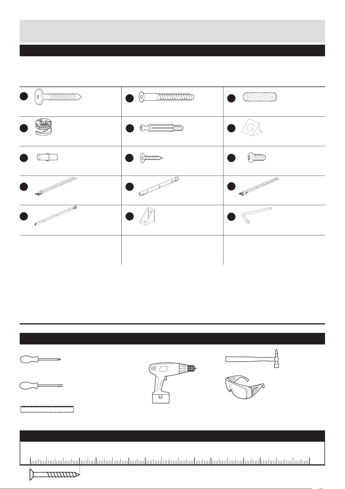
Components - Fittings
Please check you have all the ttings listed below
Note: The quantities below are the correct amount to complete the assembly. In some cases more ttings
may be supplied than are required.
A
50mm wood screw x 20
D
Locking nut x 4
G
Shelf support x 4
J
Left outside runner x 2
M N
Right inside runner x 2
B
50mm xing screw x 31
E
Screw-in dowel x 4
H
16mm wood screw x 38
K
Left inside runner x 2
Plastic support x 7
C
30mm wooden dowel x 14
F
Plastic support x 4
I
13mm xing screw x 12
L
Right outside runner x 2
O
Allen key x 1
Tools required
Phillips screwdriver
(medium & large)
Flatblade screwdriver
(medium)
0 10 20 30 40 50 60 70 80 90 100 110 120 130 140 150
0 1 2 3 4 5 6
Ruler/tape
measure
Drill
Ruler - Use this ruler to help correctly identify the screws
105
0510 15 20 25 30 35 40 45 50 55 60 65 70 75 80 85 90 95 100
The screws length is measured from the head to the point (30mm screw shown).
110 115 120 125 130 135 140 145 150 155 160 165 170
Small
hammer
Eye protection
(when using a
hammer)
4
Page 6

Assembly Instructions
Step 1
Attaching runners
Position runners J 2mm
in from front edge of the
left shelf partition 13 and
runners L 2mm in from
front edge of the right
shelf partition 14.
Fix through holes shown
using 13mm xing
screws I.
Insert the 30mm dowels
C
into left shelf partition
13
and into right shelf
partition 14.
I
Front edge
2mm
Front edge
C
I
I
I
C
J
I
I
J
C
Front edge
I I I
13
I
I
I
C
I
L
I
L
I
C
C
13
J
14
Step 2
Assemble middle
module
Screw the left shelf
partition 13 and the right
shelf partition 14 to the
middle crossbar 10, to
the back crossbar 11
and to the front crossbar
12
through 50mm xing
screws B.
Note: Use the Allen Key
O
.
B
O
Clockwise
10
B
B
B
12
13
11
14
B
B
B
5
Page 7

Assembly Instructions
Step 3
Attaching panels
a: Insert the 30mm
dowels C into left shelf
partition 13 and into right
shelf partition 14.
Position left central
support 7 to left bottom
panel 9 and right
central support 6 to
right bottom panel 8.
Fix the panels through
50mm xing screw B.
Note: Use the Allen Key
O
.
a:
B
O
7
9
B
C
B
C
13
C
C
8
Clockwise
14
6
B
b: Position the attached
panels: left central
support 7 and left
bottom panel 9 and
right central support 6
and right bottom panel
8
like shown on the
picture.
Fix the panels to left shelf
partition 13 and to right
shelf partition 14 through
50mm xing screws B.
Note: Use the Allen Key
O
.
b:
B
O
7
13
9
B
B
B
B
8
Clockwise
14
6
6
Page 8

Assembly Instructions
Step 4
Attaching panels
a: Insert the 30mm
dowels C into left side
panel 1 and into right
side panel 2.
a:
C
C
1
2
C
C
b: Position the left
side panel 1 and the
right side panel 2 like
shown on the picture and
x them to left central
support 7, left bottom
panel 9, right central
support 6 and right
bottom panel 9 through
50mm wood screws A.
Note: Use the Allen Key
O
.
b:
A
A
A
O
1
7
9
2
6
8
A
A
7
Page 9

Assembly Instructions
Step 5
Attaching panel
a: Screw plastic
supports N to the front
board 17 through 16mm
wood screws H.
First rotate the construction
of the bed horizontally
at 180 degrees and then
vertically at 90 degrees like
shown on the pictures.
a:
H
b:
H
N
H
N
H
N
H
17
N
H
N
17
H
N
N
H
N
b: Position the front
board 17 and screw it to
left central support
, middle crossbar 12
and right central support
8
through 16mm wood
screws H.
9
180
8
H
H
12
H
17
9
H
H
90
H
H
8
Page 10

Assembly Instructions
Step 6
Attaching panels
Two people are needed
here
a: Position the front bed
board 3 and the back
bed bord 4 and x them
to left shelf partition 13
and right shelf partition
14
through 50mm xing
screws B.
Note: Use the Allen Key
O
.
a:
B
B
B
B
B
B
B
B
4
3
13
14
O
Clockwise
B
b: Fix the left side panel
1
and the right side
panel 2 to the front bed
board 3 and the back
bed board 4 through
50mm wood screws A.
Note: Use the Allen Key
O
.
b:
A
A
A
A
A
3
1
4
A
O
A
A
A
9
Page 11

Assembly Instructions
Step 7
Attaching panels
Two people are needed
here
a: Position the front/
back bed supports 5
and x them to the front
bed board 3 and the
back bed board 4
through 50mm xing
screws B.
Note: Use the Allen Key
O
.
a:
B
O
Clockwise
5
5
3
B
B
4
B
B
B
b: Fix the front/back
bed supports 5 to the
left side panel 1 and
to the right side panel
2
through 50mm wood
screws A.
Note: Use the Allen Key
O
.
b:
A
A
A
A
A
1 5
5
A
A
O
A
2
A
10
Page 12

Assembly Instructions
Step 8
Attaching shelf
a: Position the shelf
supports G into the right
shelf partition 14 and the
right side panel 2.
Position the shelf 15 on
its place like shown on
the picture.
2
G
G
14
15
Step 9
Assembling drawer
a: Fold the drawer sides
18
like shown on the
picture.
b: Position the drawer
bottom 19 in the ditch of
the drawer 18 sides like
shown on the picture.
a:
18
b:
18
19
Continued on next page.
11
Page 13

Assembly Instructions
Step 9 - continued
c:
c: Position the wooden
dowels C and the screwin dowels E. Position the
drawer sides 18 and the
drawer bottom 19 onto
the front panel 16.
18
19
D
E
Insert the locking nuts D
into the drawer sides.
Use a screwdriver to turn
locking nuts D clockwise
to lock.
d: Turn the drawer with
the bottom up and place
the plastic supports
F
like shown on the
picture. Fix them with
16mm wood screws H.
Note: Place the sharp
part of the plastic support
F
in the ditch.
d:
D
E
C
C
16
H
H
F
F
D
E
C
C
e: Position the left inside
runner K and the right
inside runner M onto the
drawer and x them with
16mm wood screw H.
e:
K
H
H
H
M
H
H
M
HHH
H
12
Page 14

Assembly Instructions
Step 10
Placing drawers
Position the drawers into
the bed like shown on the
picture.
Assembly is complete.
If you need help or have damaged or missing parts, call the Customer Helpline: 0345 6400800
Domestic address or Home Retail Group Plc address.
13
Page 15

 Loading...