

Page 1
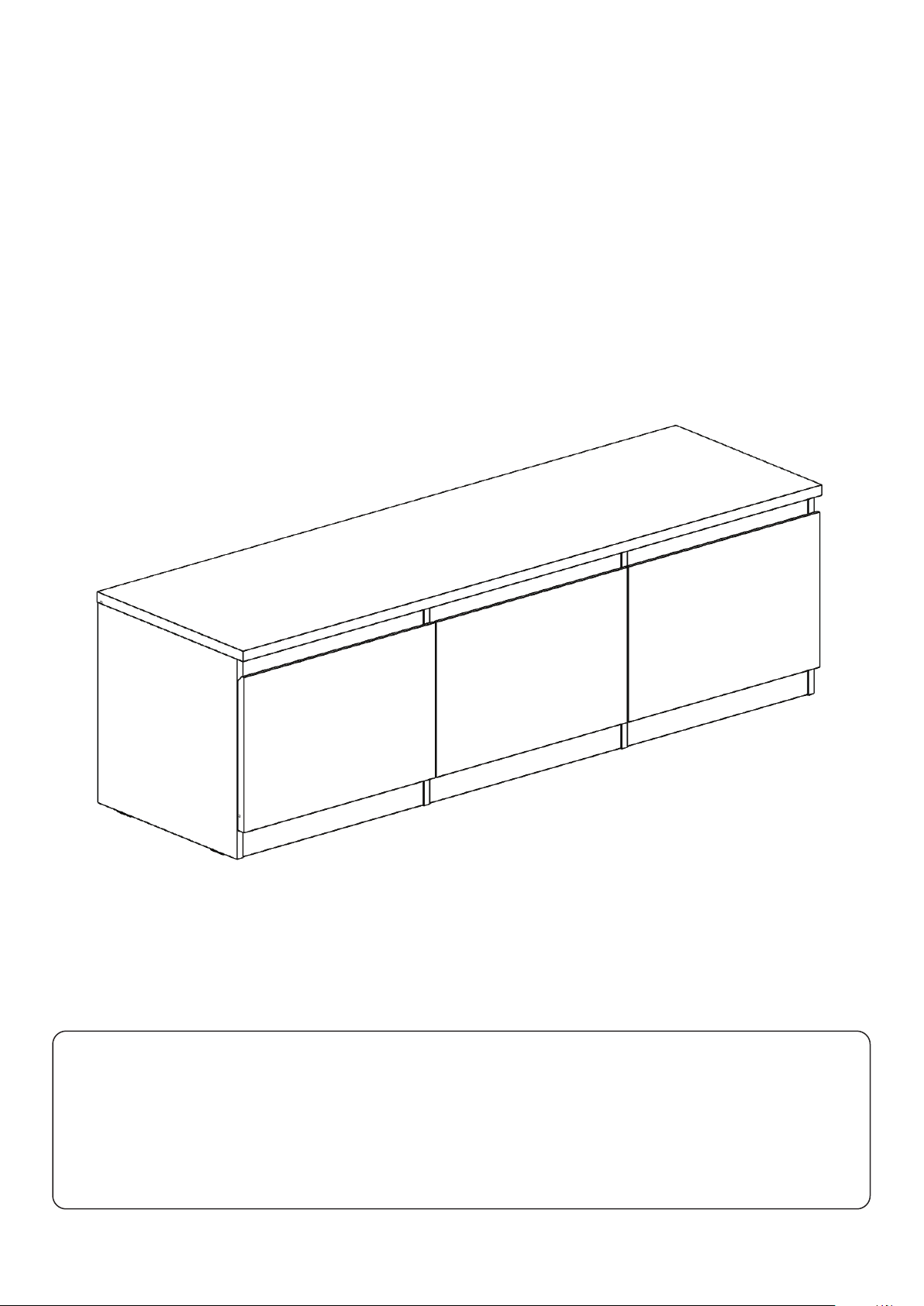
JENSON
Gloss
941/7481 853/5890
Spare Parts
Visit: www.argos-support.co.uk
Email: [email protected]
Call: 0330 016 1114
Customer Support
Call: 0345 640 2020
Issue 1 - 11/12/20
Page 2
Safety
Important - Please read these instructions fully before starting assembly
• Warning: This unit weighs
approximately 43kgs.
Please lift with care.
• During assembly children
should be kept away from the
product due to possible risk of
injury.
• Installation shall only be
carried out exactly according to
the manufacturer’s instructions otherwise a safety risk can
occur if incorrectly installed.
• Do not use this item if any
components are missing or
damaged.
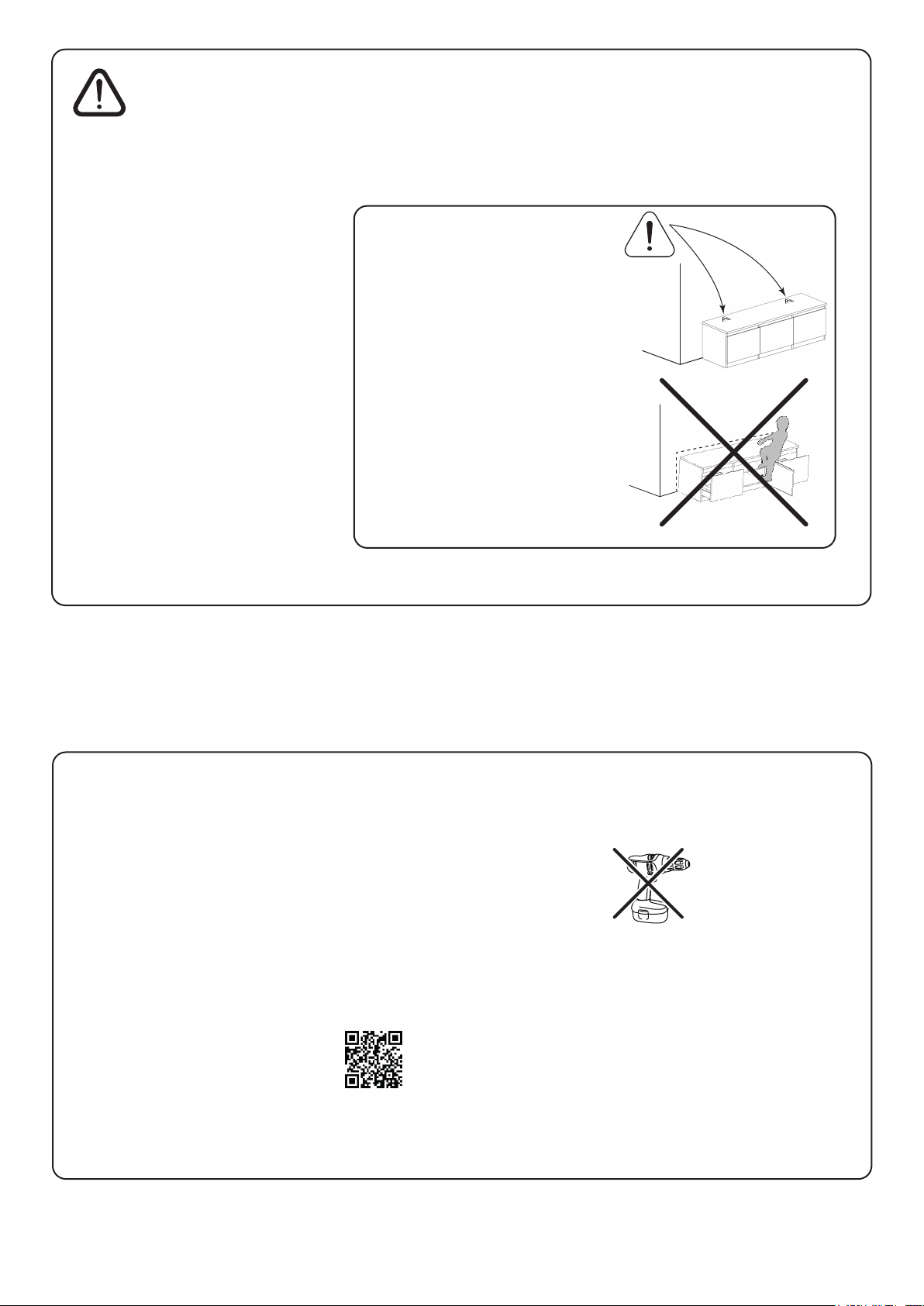
• WARNING: To prevent
possible overbalancing this unit
must be secured to a wall using
the 2 overbalance protector kits
supplied.
• A unit that is allowed to topple
can cause serious or fatal injury.
In addition to wall fixing the unit,
place heavy items on the lower
shelves, do not put any heavy
objects on top of the unit and
never allow children to climb or
hang on drawers, doors or
shelves.
• Refer to guide after section 36
for wall fixing information.
Care Advice
• Check you have all the
components and tools listed on
relevant pages.
• Remove all fittings from the
specified plastic bag and
separate them into their groups.
• Parts of the assembly will be
easier with 2 people.
• Make sure you have enough
space to layout the parts before
starting.
• Do not stand or put weight on
the product, this could cause
damage.
• Assemble the item as close to
its final position (in the same
room) as possible.
• Assemble on a soft level
surface to avoid damaging the
unit or your floor (use opened
out unit carton).
• Assembly videos are
available throughout
these instructions by
scanning in the QR
codes.
• We do not
recommend the
use of power
drill/drivers for
inserting screws,
as this could damage the unit.
Only use hand screwdrivers.
• Dispose of all packaging
carefully and responsibly.
• Only clean with a damp cloth.
Page 3
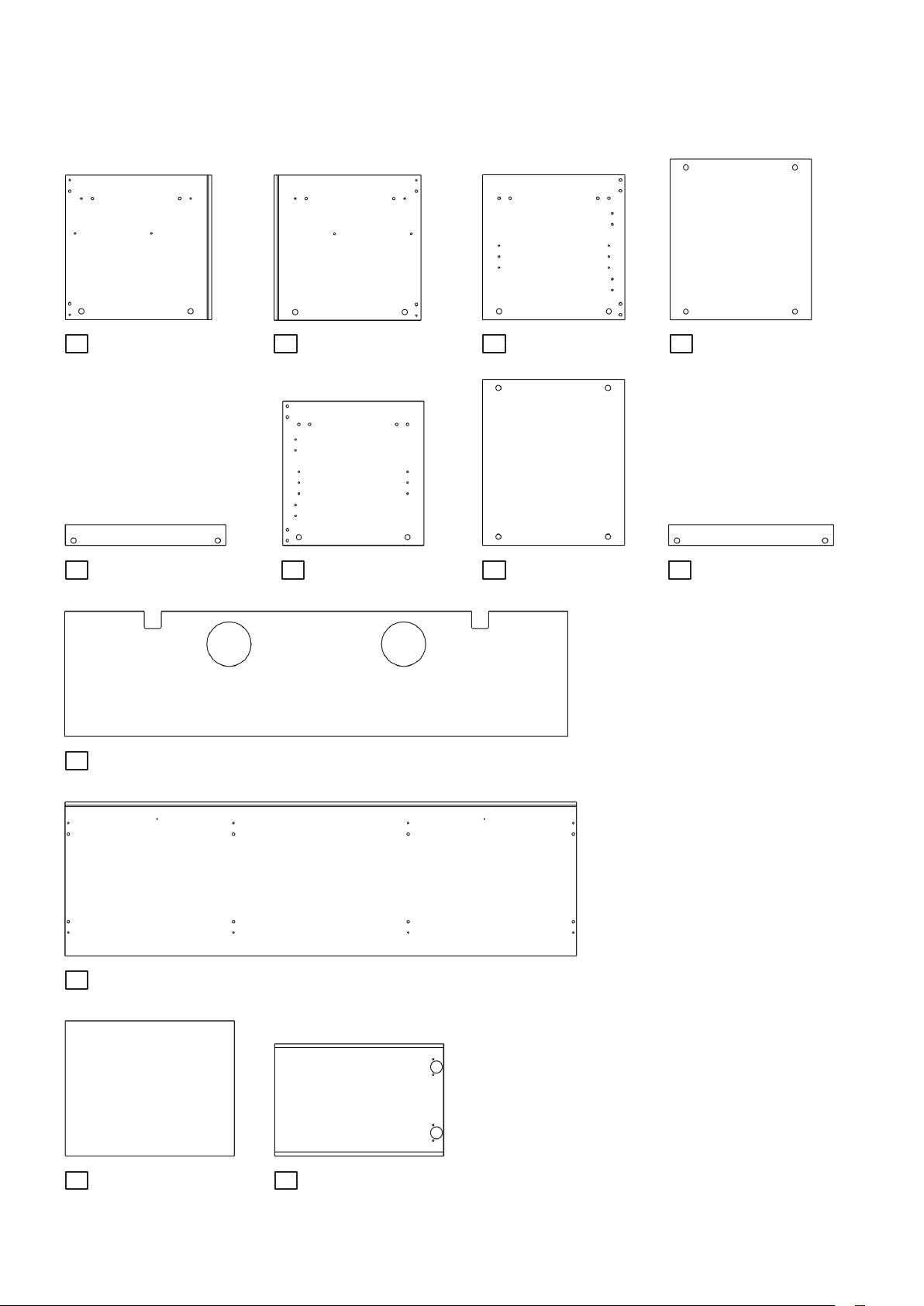
Cabinet Panels
Please do NOT remove any protective film until after assembly
1
42.3 x 42.9cm
5
46.9 x 6.0cm x 4
9
147.5 x 36.5cm
DF-00022936
2
DF-00022929
6
42.3 x 42.9cm
42.3 x 41.5cm
DF-00022935
3
DF-00022833
7
42.3 x 41.5cm
49.7 x 41.4cm
XDF-00022923
DF-00022834
4
46.9 x 41.4cm x 2
DF-00022932
8
49.7 x 6.0cm x 2
DF-00022930
DF-00022931
10
149.9 x 45.0cm
11
49.7 x 39.6cm
DF-00022934
12
49.5 x 32.7cm
DF-00022922
DF-00022823
Page 4
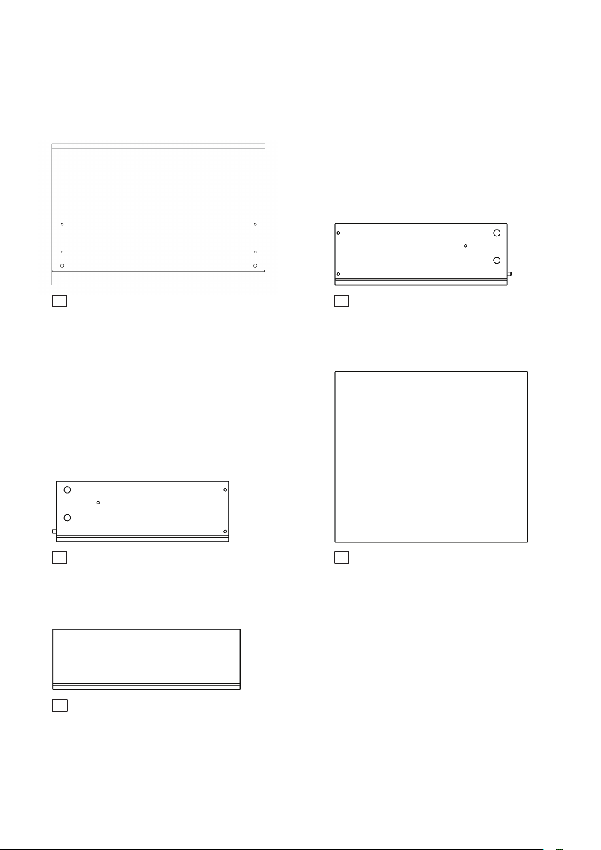
Drawer Panels
Note: the internal drawer panels are grey
Please do NOT remove any protective film until after assembly
13
49.5 x 32.7cm
15
40.0 x 14.0cm
x 2
x 2
DF-00022926
WRP-00000429
14
40.0 x 14.0cm
16
44.75 x 39.7cm
WRP-00000430
x 2
TDF-00022937
x 2
17
43.65 x 14.0cm
WRP-00000486
x 2
Page 5
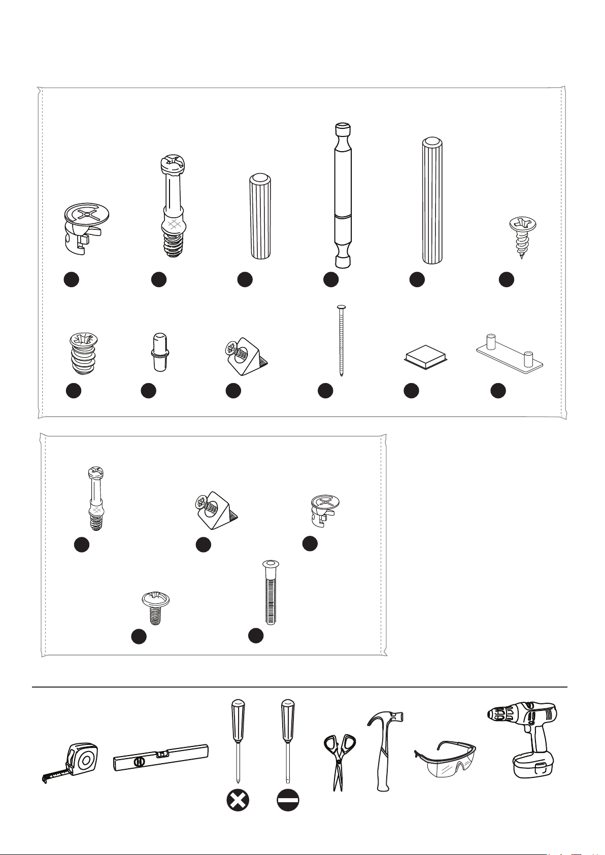
Fittings
Use these drawings to
correctly identify the fittings
Bag 1
A
G
x 32
x 8
F900
F73
F901
F901
B
x 16
F110
H
x 4
C
I
x 9
x 16
F22
F639
J
D
x 8
x 13
F566
F51
F40
E
x 8
F137
K
x 6
F
L
F63
x 4
F646
x 8
Bag 2
F639
F607
B
Tools
x 8
M
I
x 8
F74
N
x 4
O
F171GY
x 8
x 8
Only used for
drilling walls
Page 6
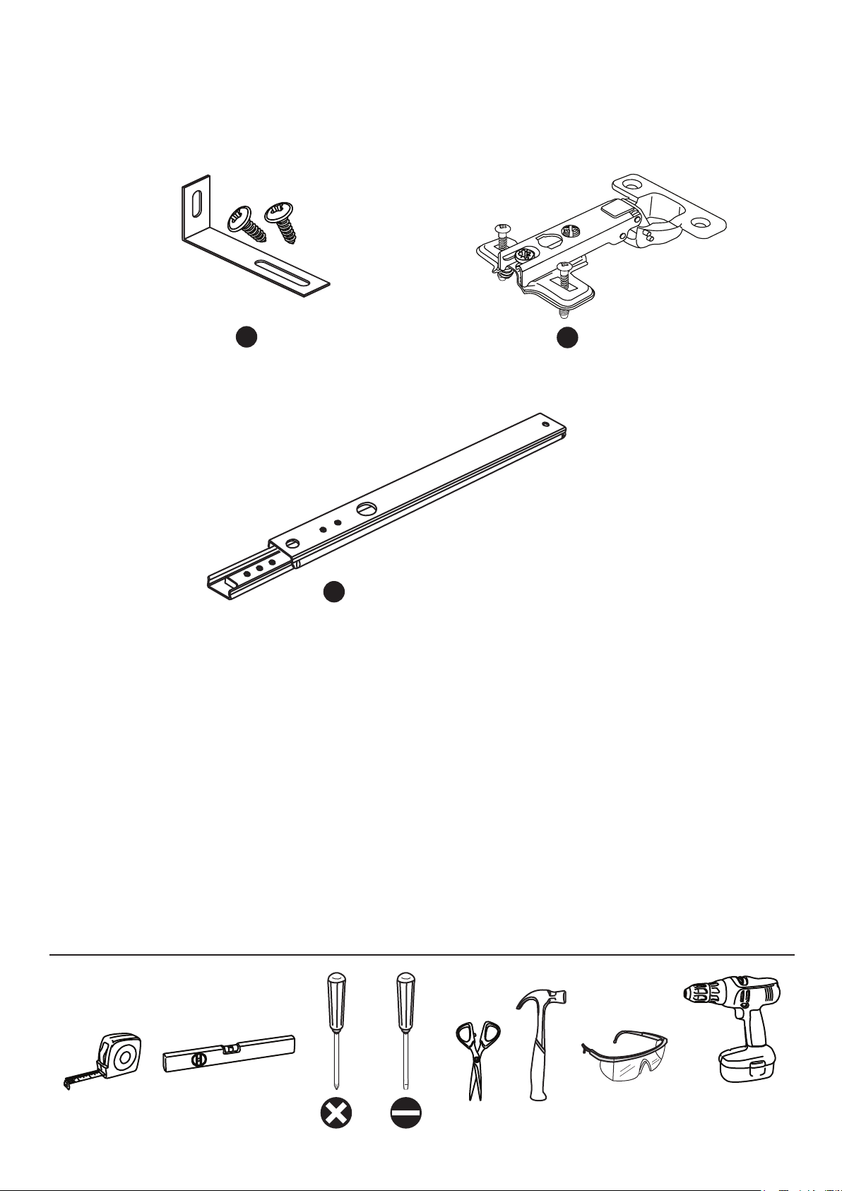
Fittings
Use these drawings to
correctly identify the fittings
F328
F474
P
x 2
Q
x 2
F450
Tools
R
x 4
Only used for
drilling walls
Page 7
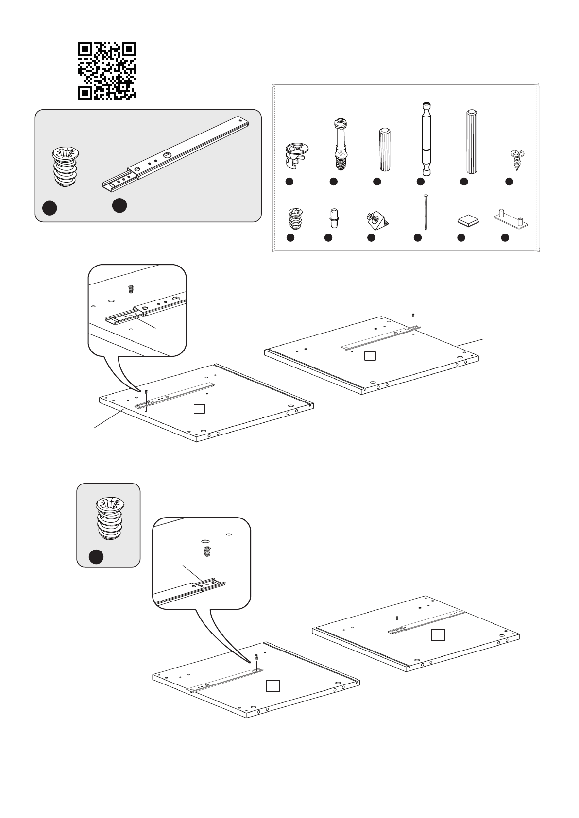
1
Fitting Ball Bearing Runners
www.youtube.com/watch?v=yG4xtiJJeSg
Bag 1
G
x 2
Finished
front edge
R
x 2
2nd hole
F900
A
x 32
F73
G
x 8
F901
B
x 16
F110
H
x 4
F22
C
x 16
F639
I
x 9
F566
D
x 8
F51
J
x 13
F40
E
x 8
F137
K
x 6
F63
F
x 4
F646
L
x 8
Finished
front edge
2
1
2
G
x 2
2nd hole
2
1
Page 8
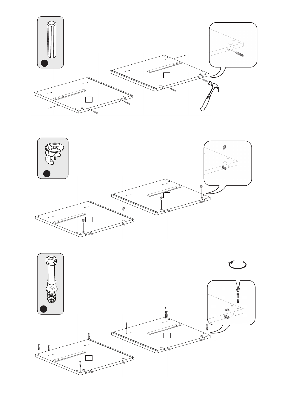
3
Finished
front edge
4
Finished
front edge
C
x 4
2
1
5
A
x 4
2
1
B
x 8
2
1
Page 9
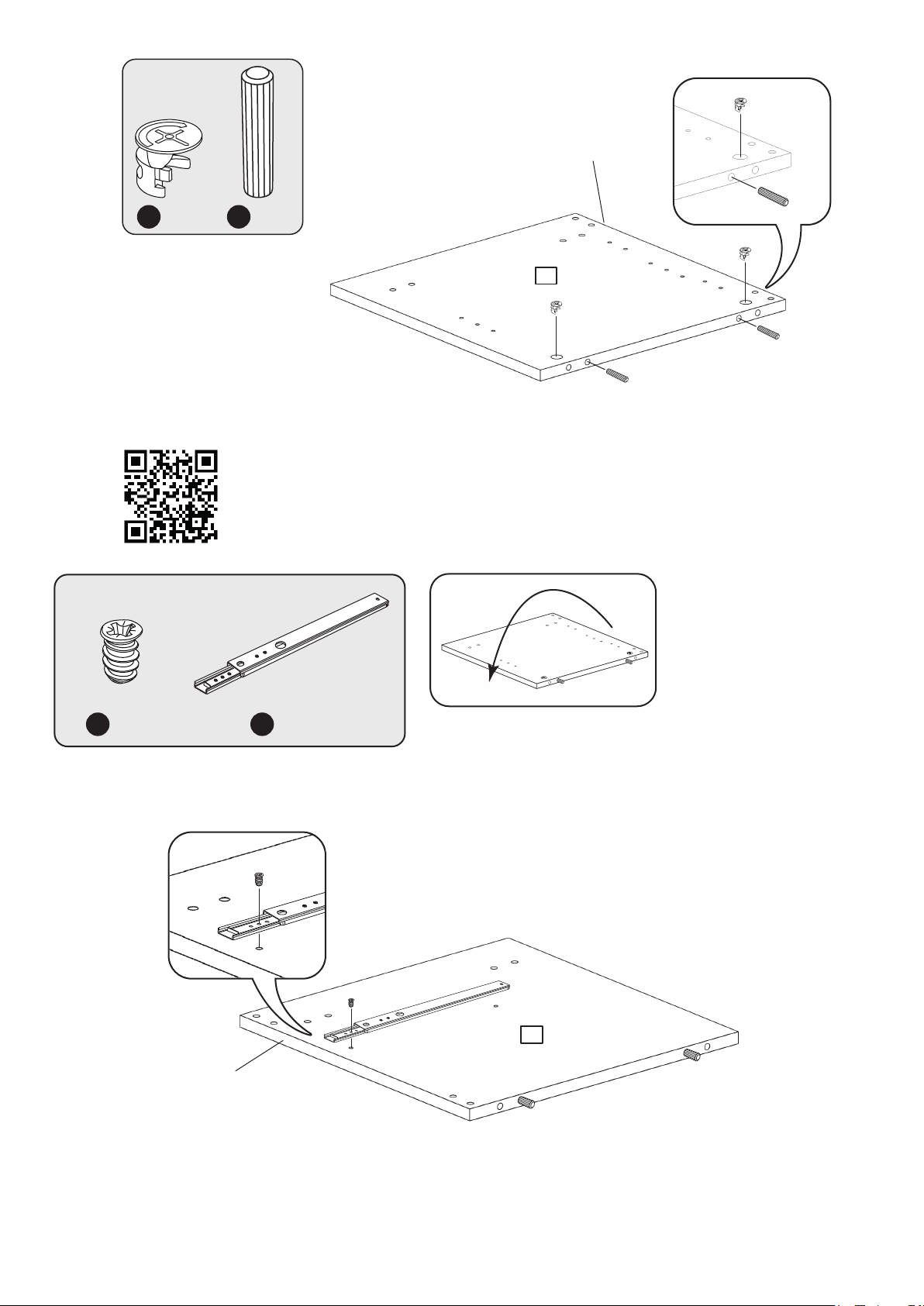
6
Finished
front edge
7
A
x 2
C
x 2
Fitting Ball Bearing Runners
www.youtube.com/watch?v=yG4xtiJJeSg
3
G
x 1
Finished
front edge
R
x 1
3
Page 10
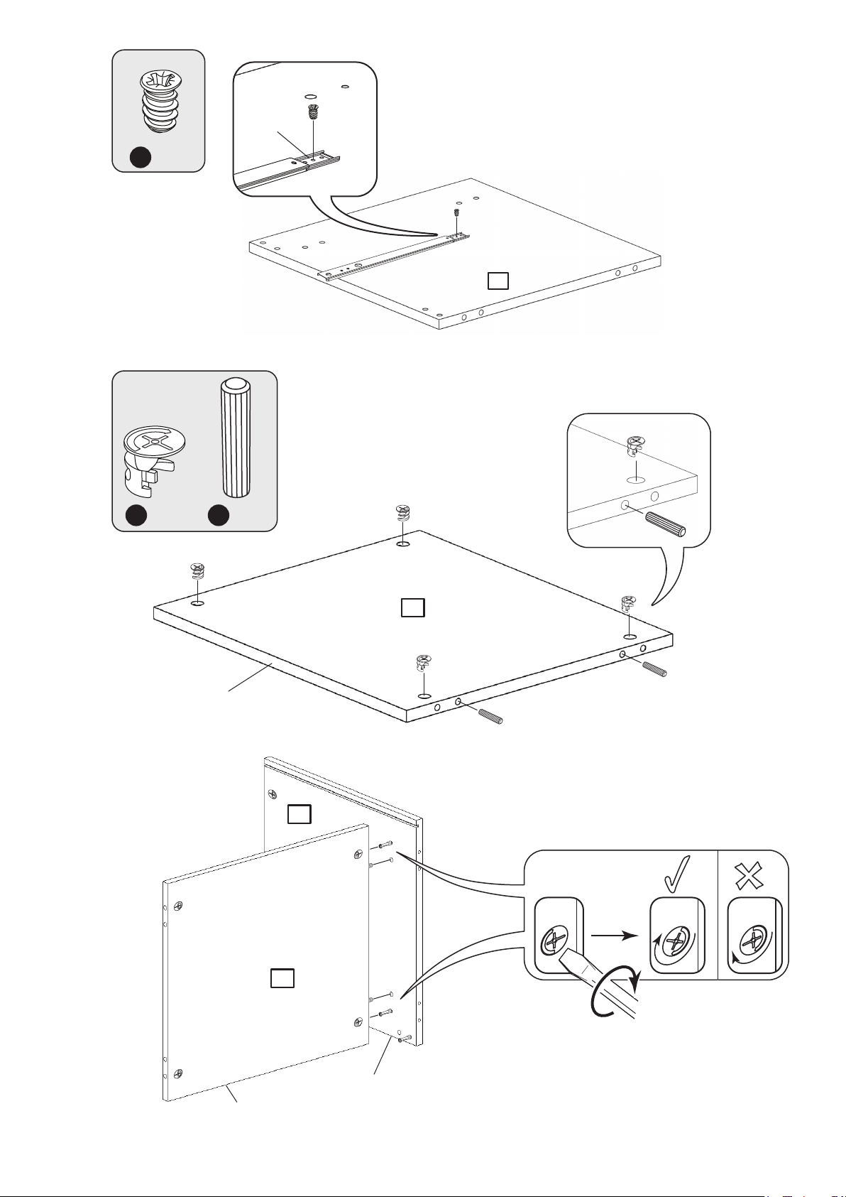
8
9
G
2nd hole
x 1
3
A
10
x 4
Finished
front edge
C
x 2
4
2
x 2
4
Finished
front edge
Finished
front edge
Page 11
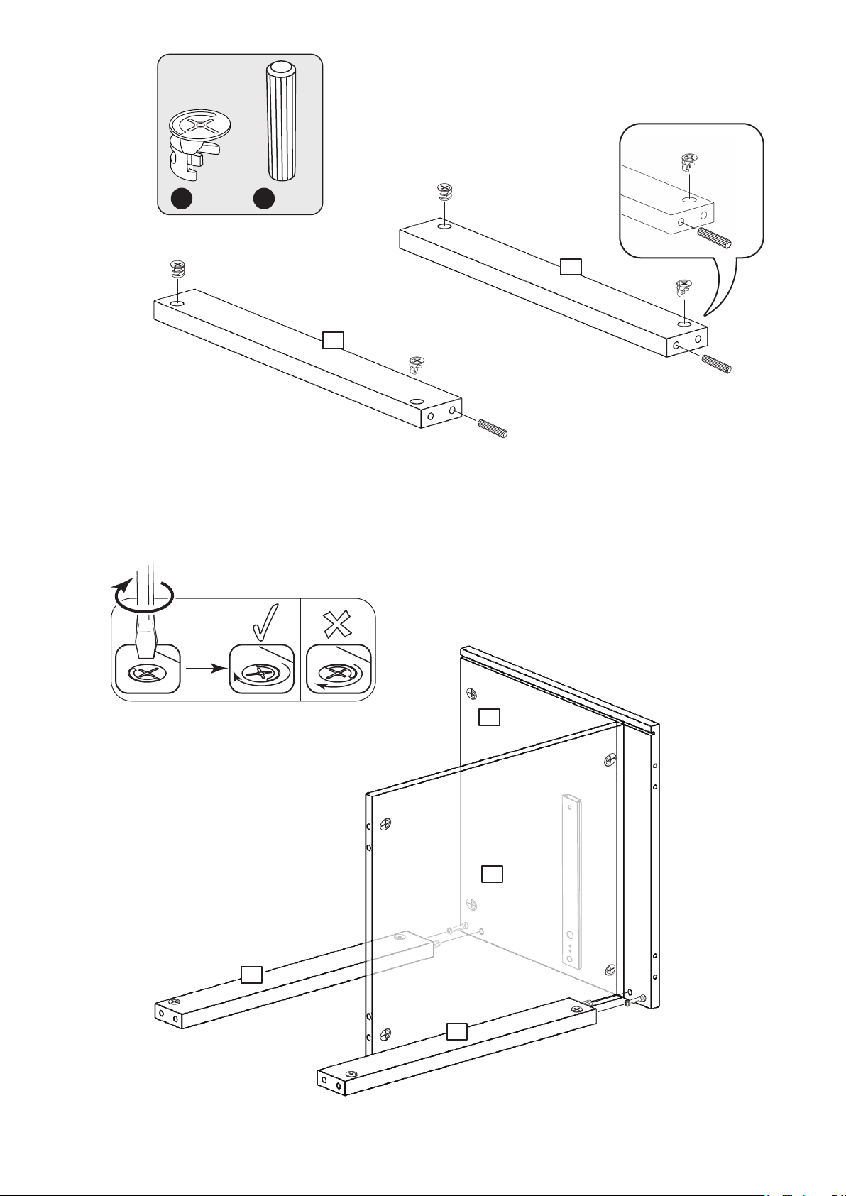
11
12
A
x 4
C
x 2
5
5
x 2
2
4
5
5
Page 12
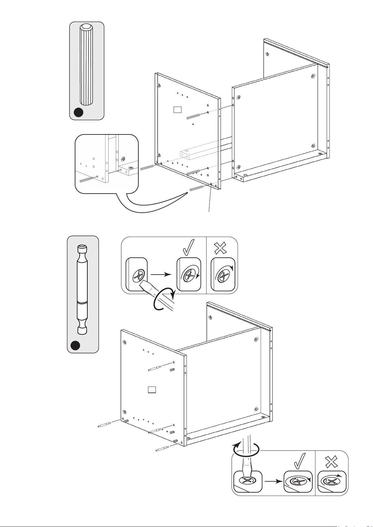
13
F
D
14
E
x 4
3
Finished
front edge
x 2
D
x 4
3
x 2
Page 13
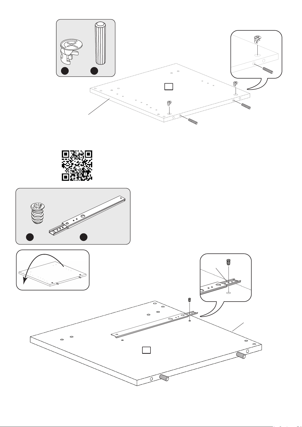
15
16
A
x 2
Finished
front edge
C
x 2
6
Fitting Ball Bearing Runners
www.youtube.com/watch?v=yG4xtiJJeSg
G
x 1
R
x 1
2nd hole
Finished
front edge
6
Page 14
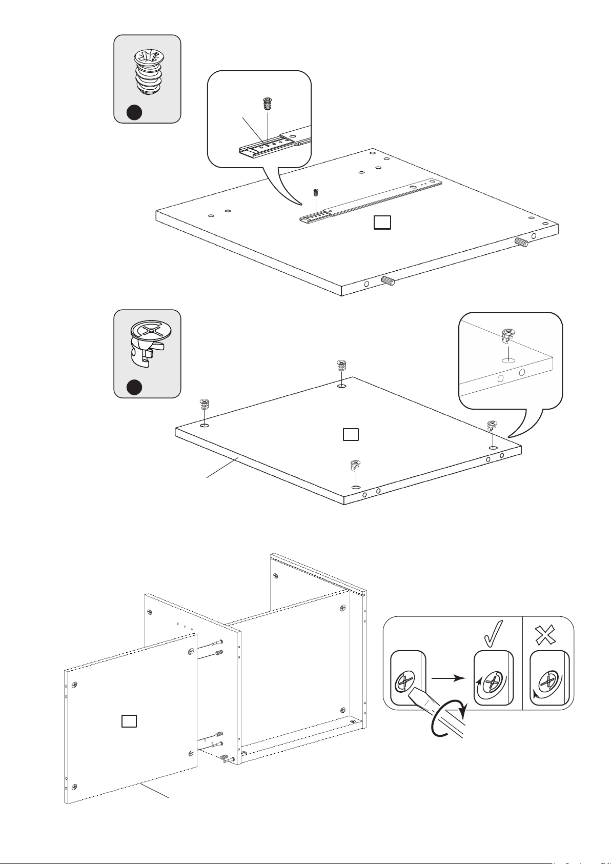
17
18
G
A
x 1
x 4
2nd hole
6
19
7
Finished
front edge
x 2
7
Finished
front edge
Page 15
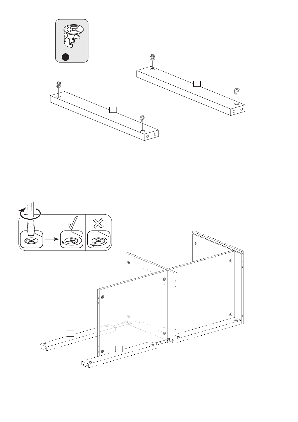
20
A
x 4
8
8
21
x 2
8
8
Page 16
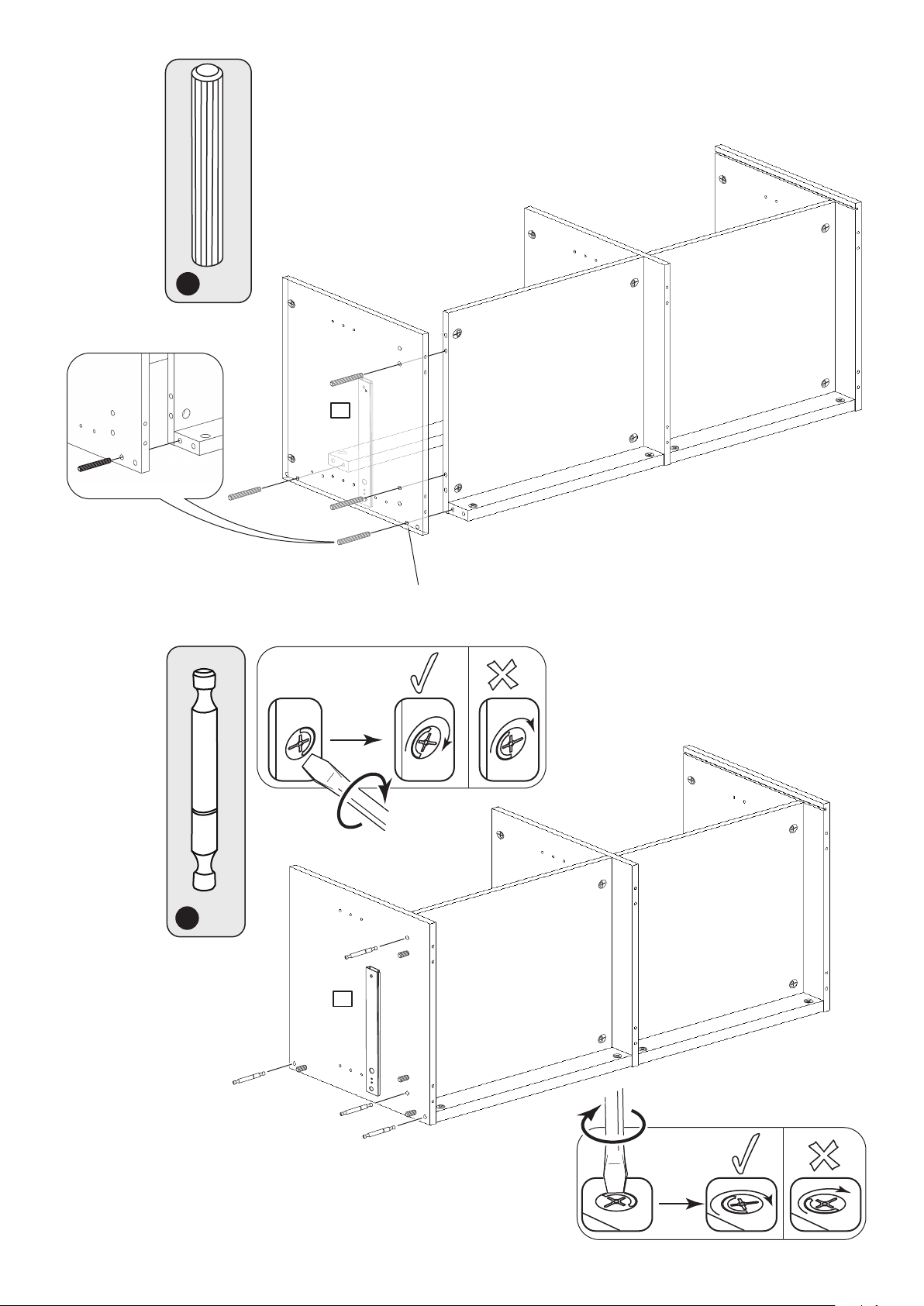
22
E
x 4
6
23
Finished
front edge
x 2
D
x 4
6
x 2
Page 17
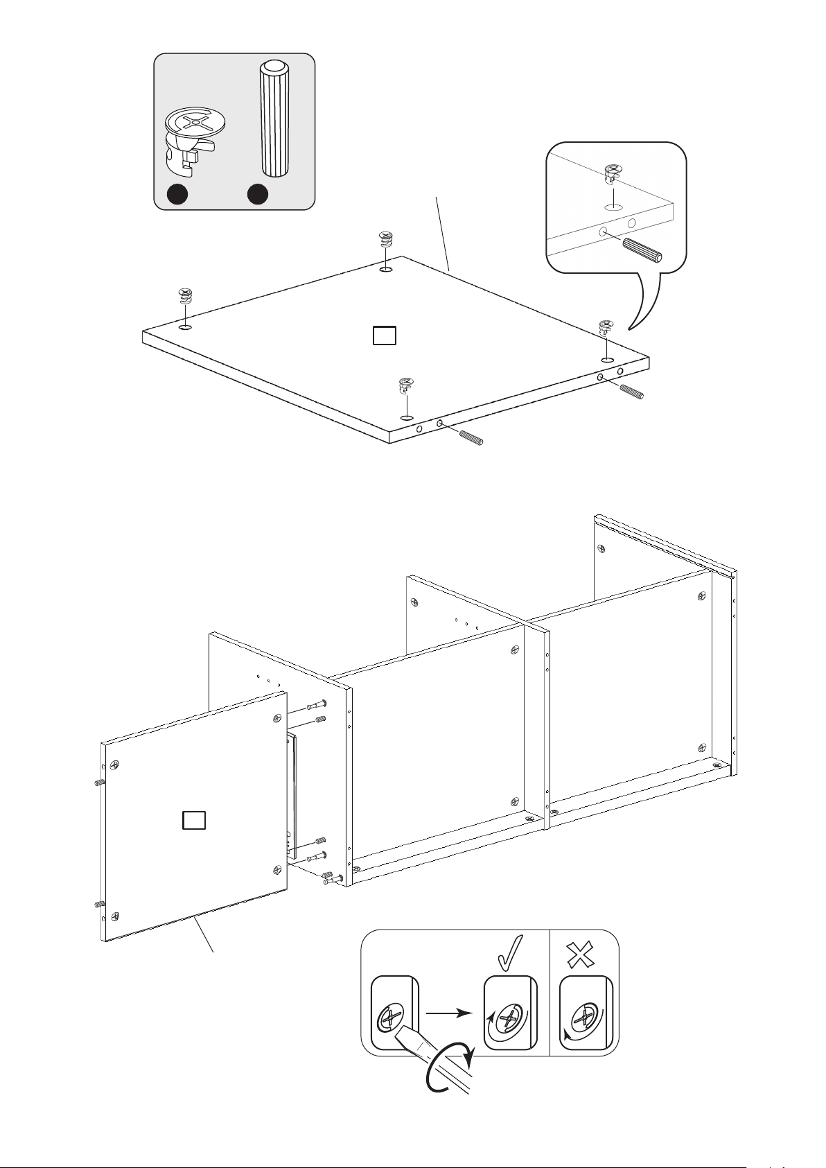
24
Finished
A
x 4
C
x 2
front edge
4
25
4
Finished
front edge
x 2
Page 18
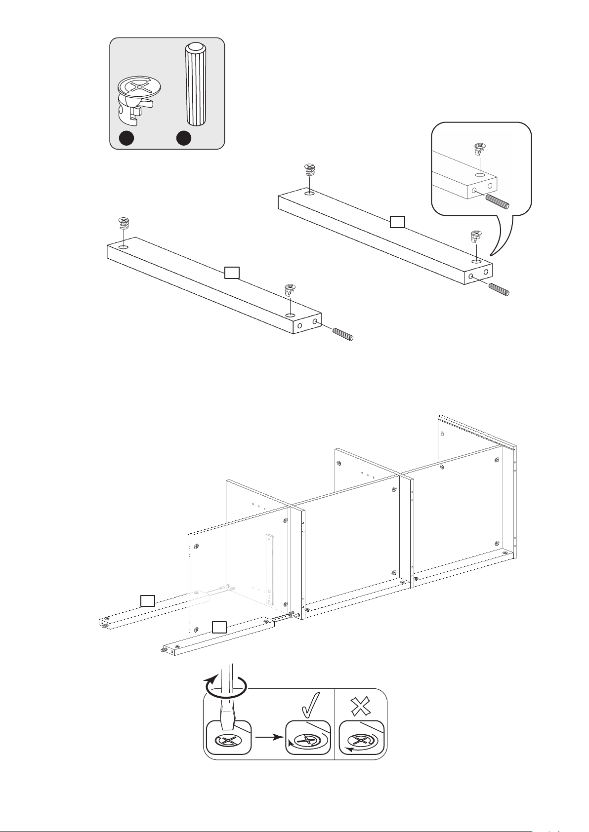
26
A
x 4
C
x 2
5
5
27
5
5
x 2
Page 19
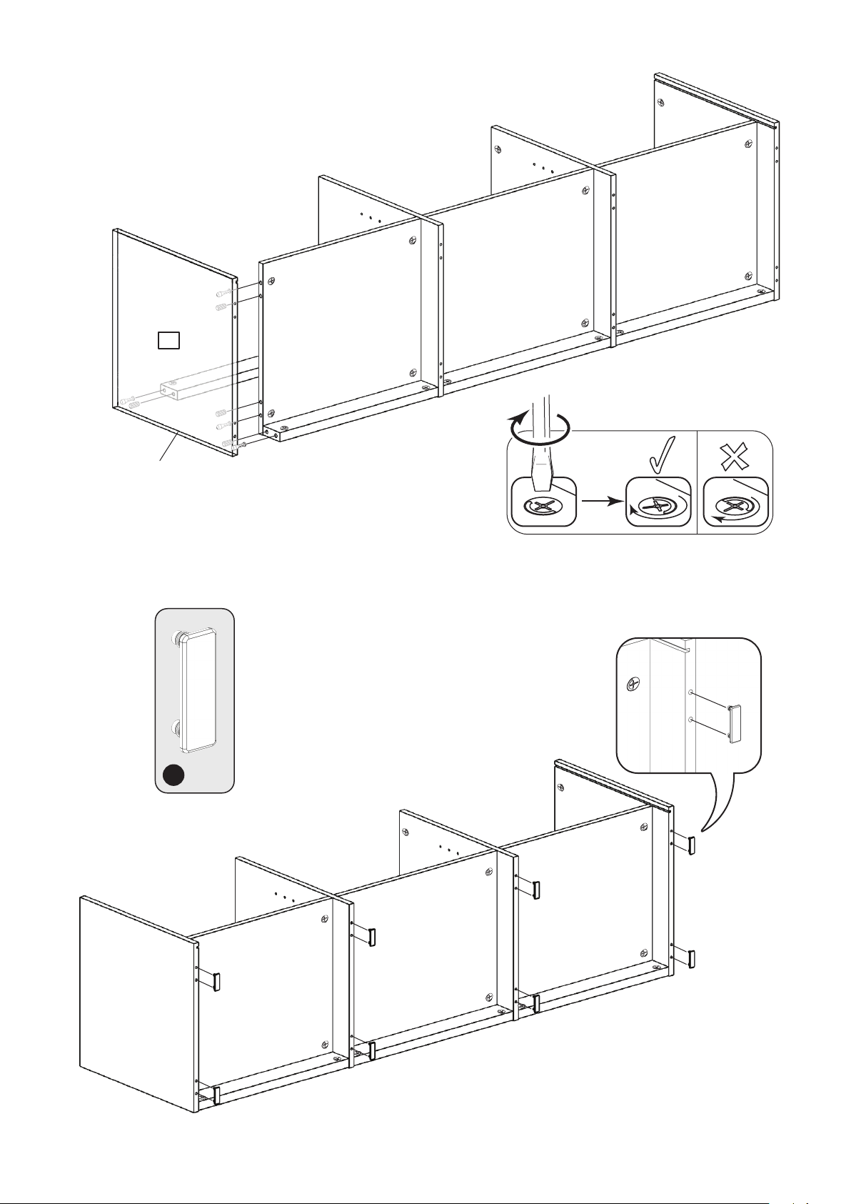
28
1
Finished
front edge
29
x 2
L
x 8
Page 20
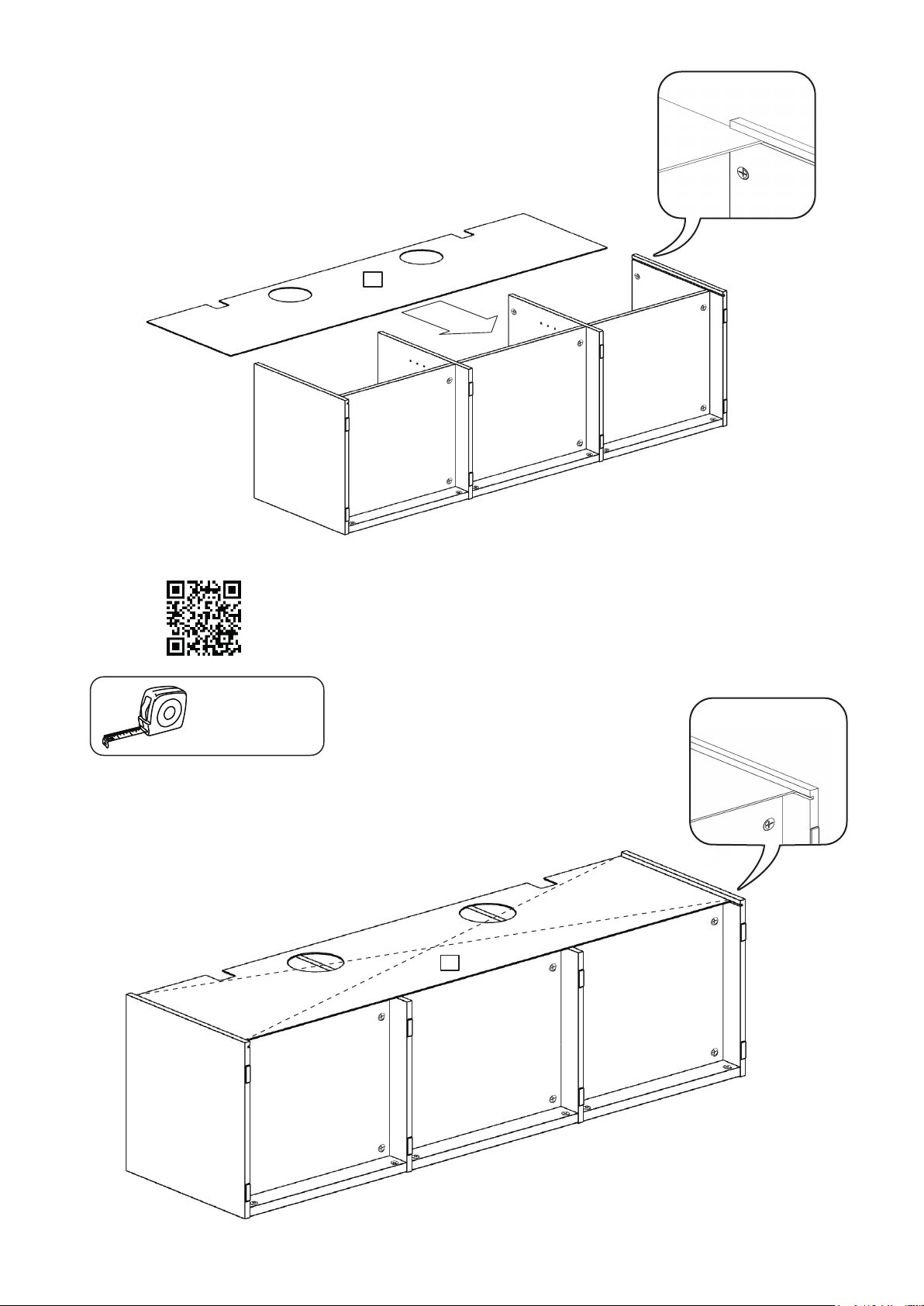
30
9
31
Make sure measurement
A and B are the same
Squaring up a Chest and fitting the Back Panel
www.youtube.com/watch?v=FeaI6541z7o
The Back panel must be
flush with the Back Rail.
A = B
B
9
A
Page 21
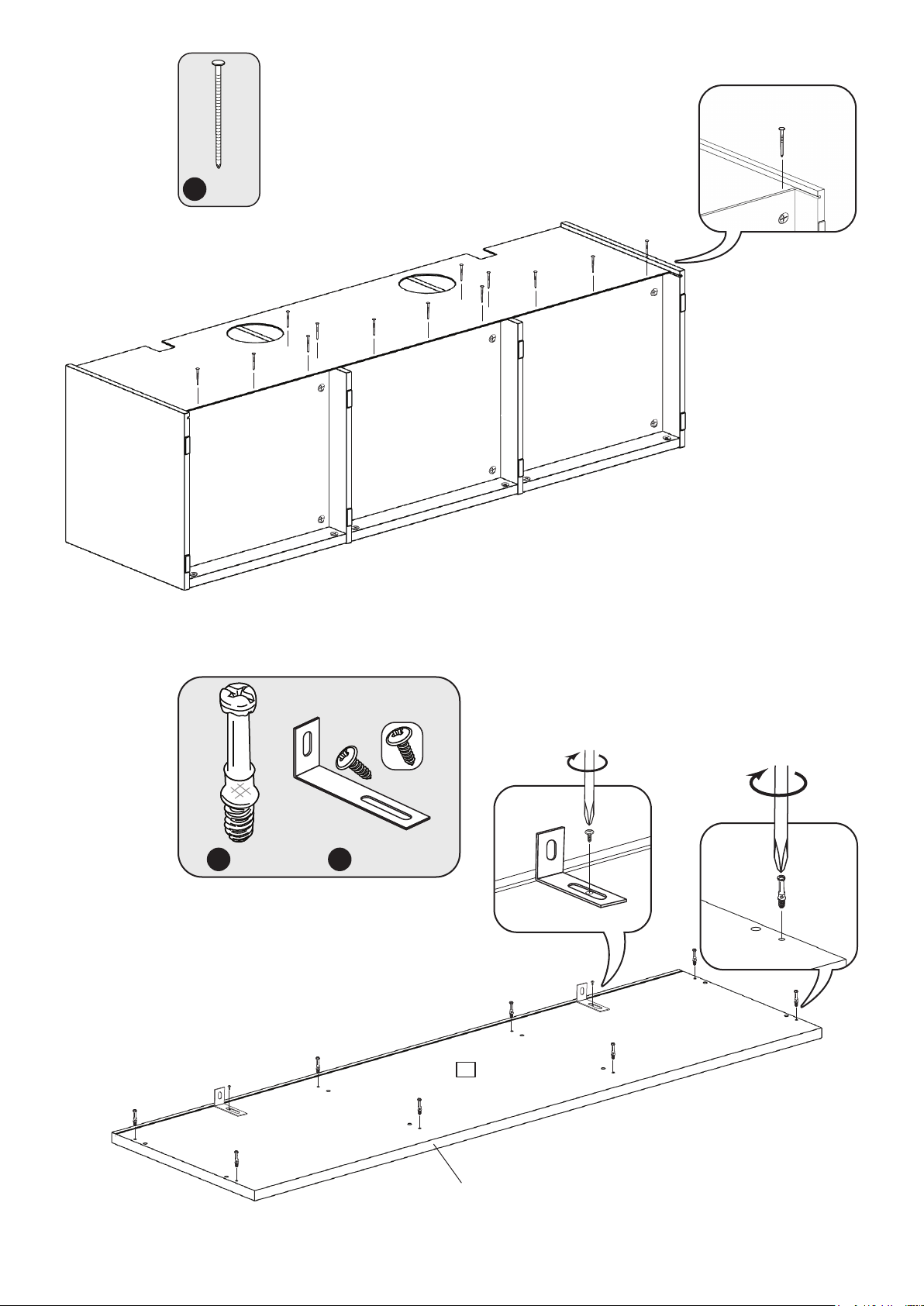
32
J
x 13
33
B
x 8
P
x 2
Only use 1 Screw
to fit each Bracket
10
Finished
front edge
Page 22
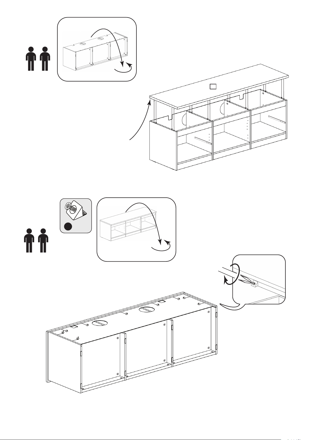
34
10
IMPORTANT:
The Back panel must
slot into the groove
in the Top panel
35
I x 9
Page 23
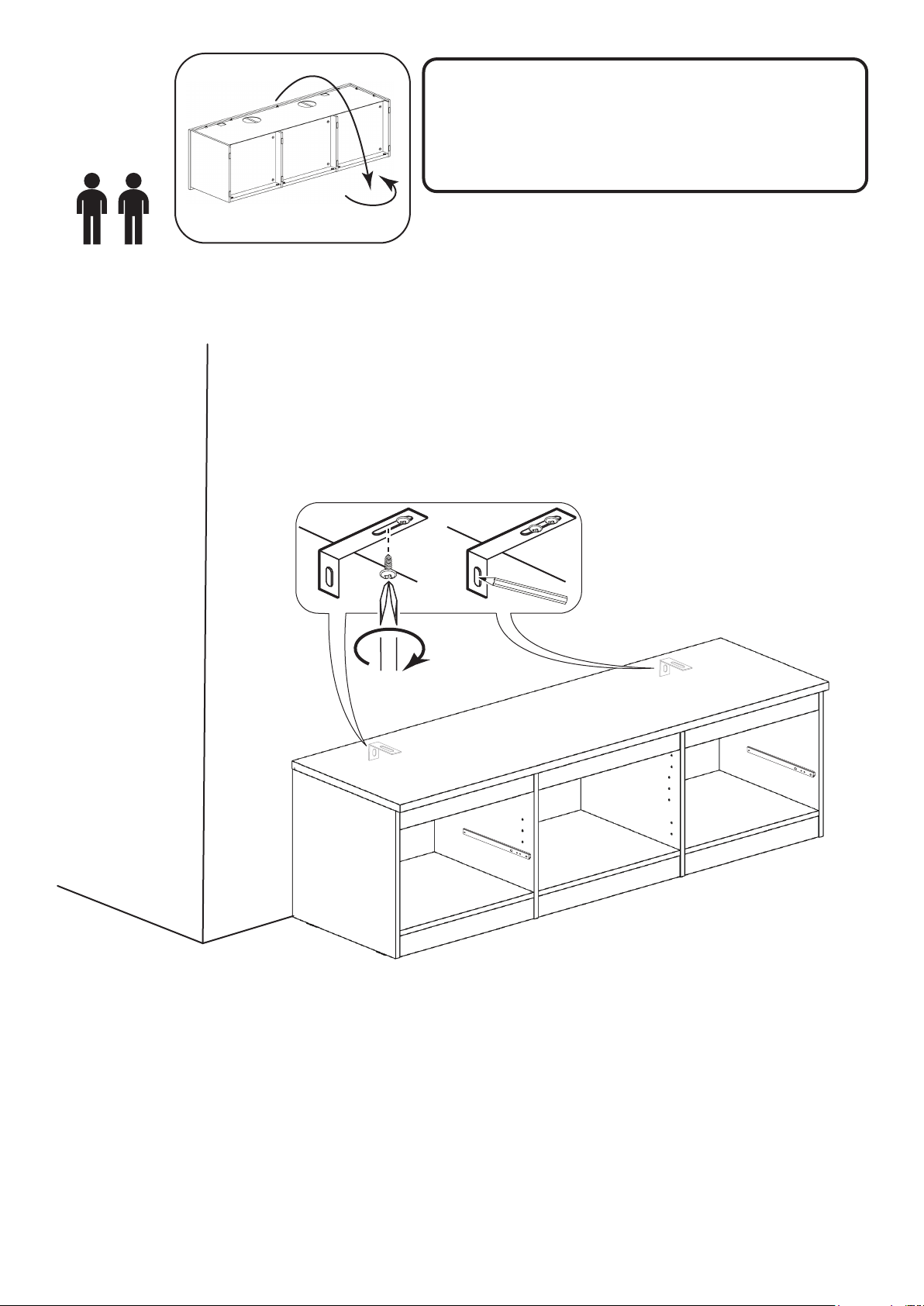
WARNING!
36
In order to prevent overturning
this product must be used with the 2
wall attachment devices provided
See the next section for a guide
to wall mounting and fixings
Top
Slide the Brackets against the wall. Fit the 2nd screws supplied
with the Brackets into the underside of the Top panel.
Mark the slot at the back of the Brackets for drilling into the wall.
Wall fixings are not supplied as they will need to suit the wall type.
Take care when drilling the wall that you do not drill
Note:
into any pipes, wires etc.
If in doubt, consult an expert.
Page 24
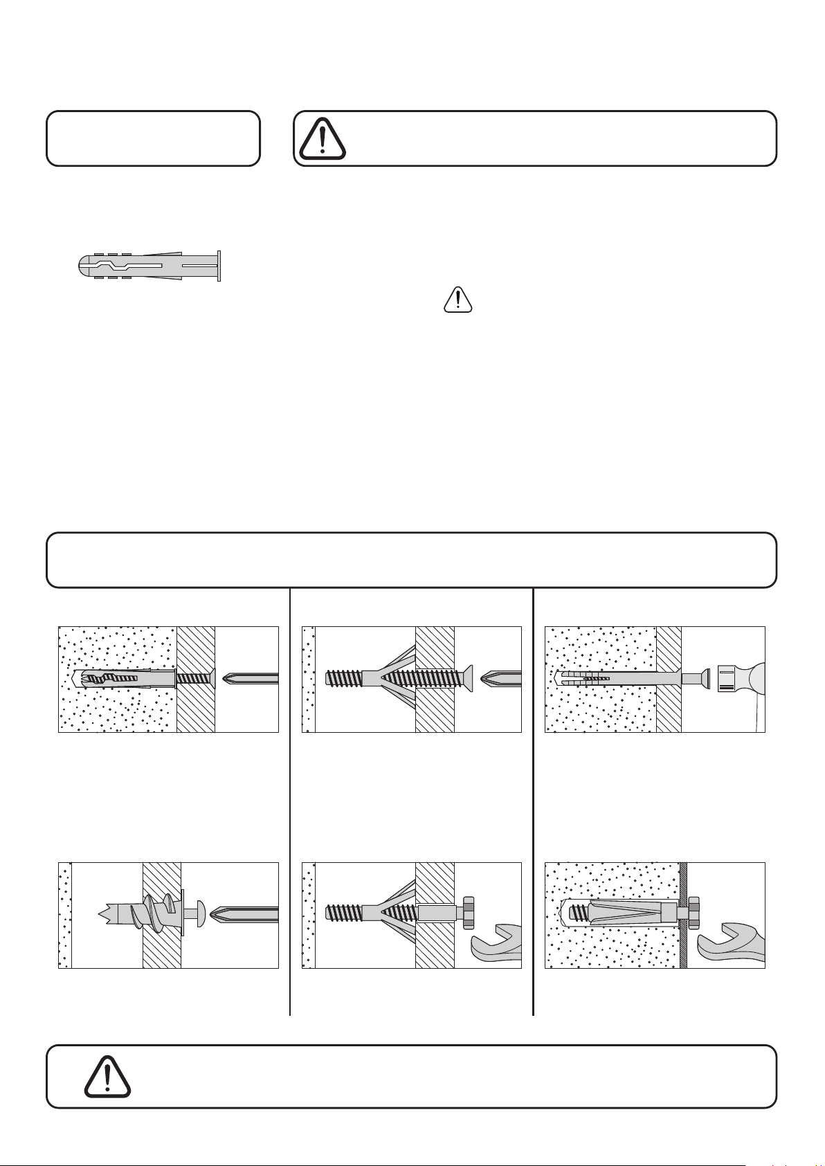
A Guide to Wall Mounting & Fixings
Important note:
If plastic wall plugs
are supplied with your
product:
- these are only suitable for
use in masonry walls.
If you are in any doubt about
the correct wall plugs for
your wall, seek professional
advice.
Failure of the product due to
using incorrect fixings is the
responsibility of the installer.
Important: When drilling into walls always
check that there are no hidden wires or pipes etc.
Make sure that the screws and wall plugs being used
are suitable for supporting your unit. Consult a qualified
tradesperson if you are unsure.
Hints:
1: General rule: Always use a larger screw and wall plug
if you are not sure.
2: Ensure you use the recommended drill bit to match the wall
plug and hole size.
3: Ensure you drill the hole horizontally, do not force the drill or
enlarge the hole.
4: Take extra care when drilling high walls, ceilings and ceramic
tiles. Ensure wall plugs are inserted beyond the thickness of
the ceramic tiles to avoid the tiles splitting or cracking.
5: Ensure wall plugs are well fitted and are a tight fit in the
drilled hole.
Types of walls
No.1 “General Purpose” wall plug No.3 “Cavity Fixing” wall plug No.5 “Hammer Fixing” wall plug
Generally aerated blocks should not
be used to support heavy loads, use
a specialist fitting in this case. For light
loads, general purpose wall plugs can
be used.
No.2 “Plasterboard” wall plug
You can use one of the following types of wall plug if your
walls are made of brick, breeze block, concrete, stone or wood.
For use with plasterboard partitions or
hollow wooden doors.
No.4 “Cavity Fixing-Heavy Duty”
wall plug
For use with walls stuck with
plasterboard. The hammer fixing allows
it to be fixed to the wall rather than the
plasterboard. Always check the fixing
is secure to the retaining wall.
No.6 “Shield Anchor” wall plug
Heavy loads
For use when attaching light loads on
to plasterboard partitions.
Care &
Maintenance
For use when fitting or supporting
heavy loads such as shelving, wall
cabinets and coat racks.
Safety: Always check the fitting
and location to ensure your safety
in and around the home.
For use with heavier loads such as TV
& HiFi speakers and satelite dishes etc.
Fitting: From time to time check
the fitting to ensure the wall plugs
or screws do not become loose.
Page 25
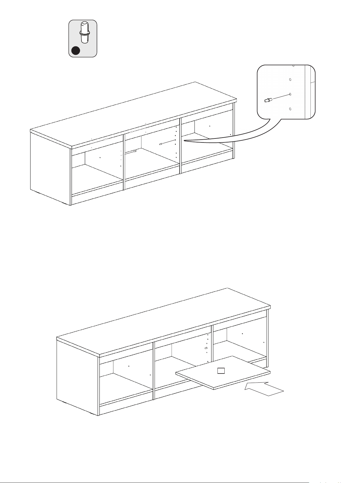
37
H
x 4
38
11
Page 26
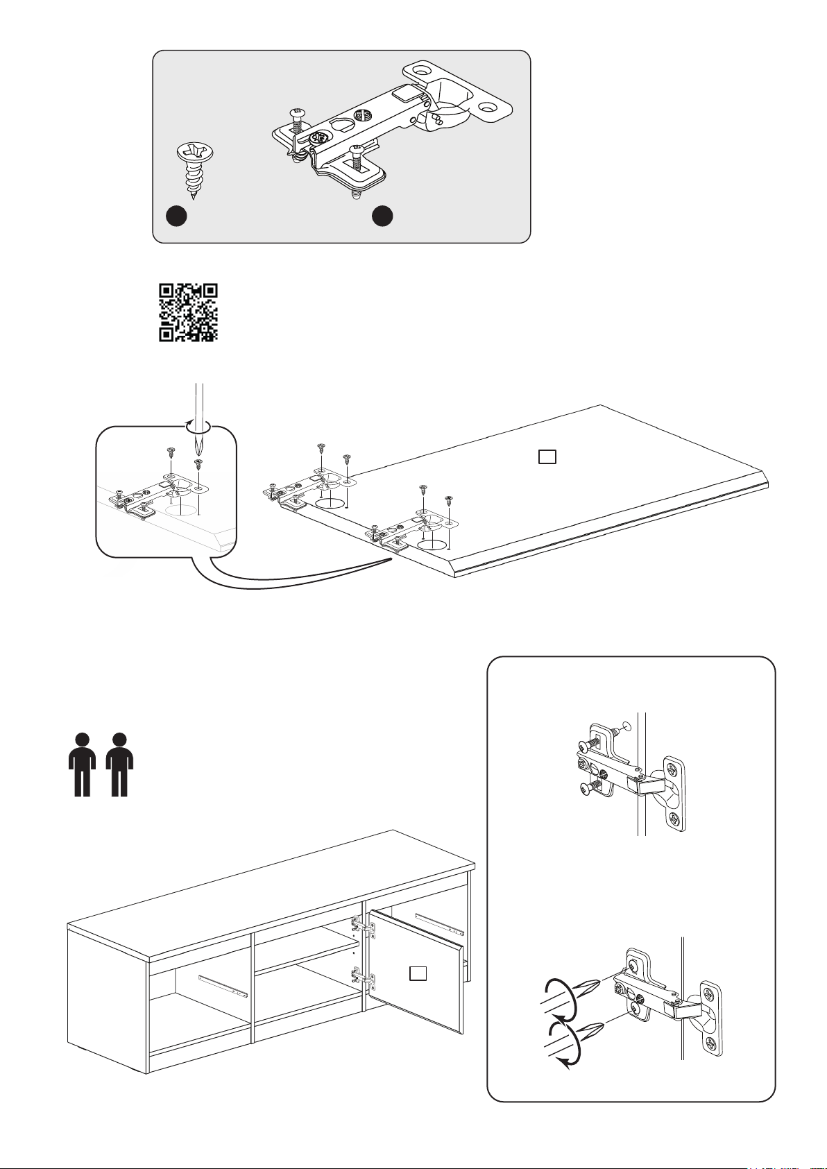
39
F
x 4
Pre-mounted Hinge Fitting & Adjustment
https://www.youtube.com/watch?v=b4NeCGnpjP8
Q
x 2
12
40
Press the screws into the
holes in the panels
When the hinges have been pushed
in, tighten up their screws
12
Page 27
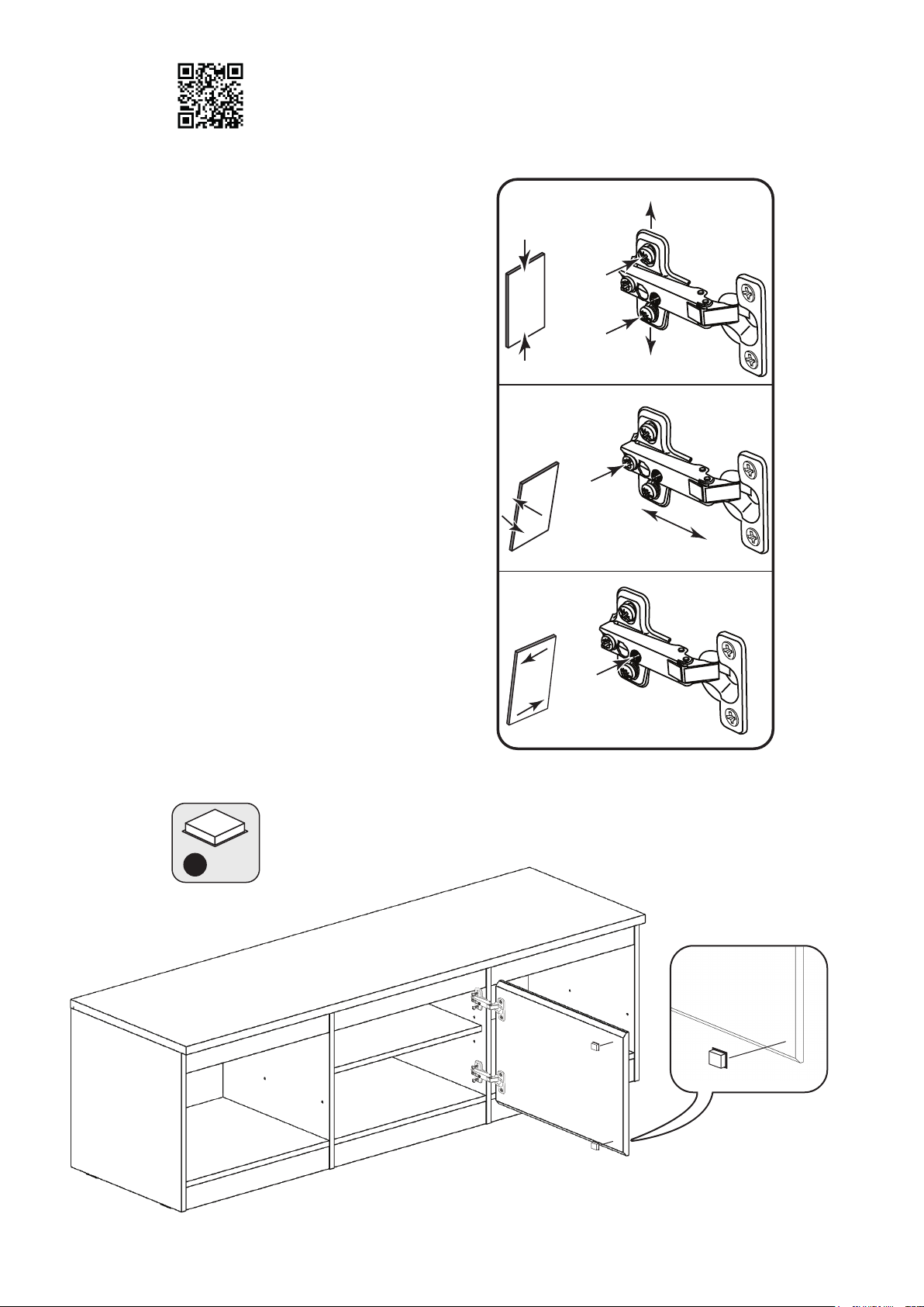
41
Adjust the Door if required
a: Height adjustment.
Loosen screws A on Hinge Plates and
move Door up or down as required.
Retighten screw A.
b: Forward and Back adjustment.
Loosen screw B on Hinge Plate and
move door in or out as required.
Retighten screw B.
Pre-mounted Hinge Fitting & Adjustment
https://www.youtube.com/watch?v=b4NeCGnpjP8
a:
A
A
b:
B
c: Sideways adjustment.
To move door ‘out’ loosen screw C.
To move door ‘in’ tighten screw C.
42
c:
C
K
x 2
Page 28
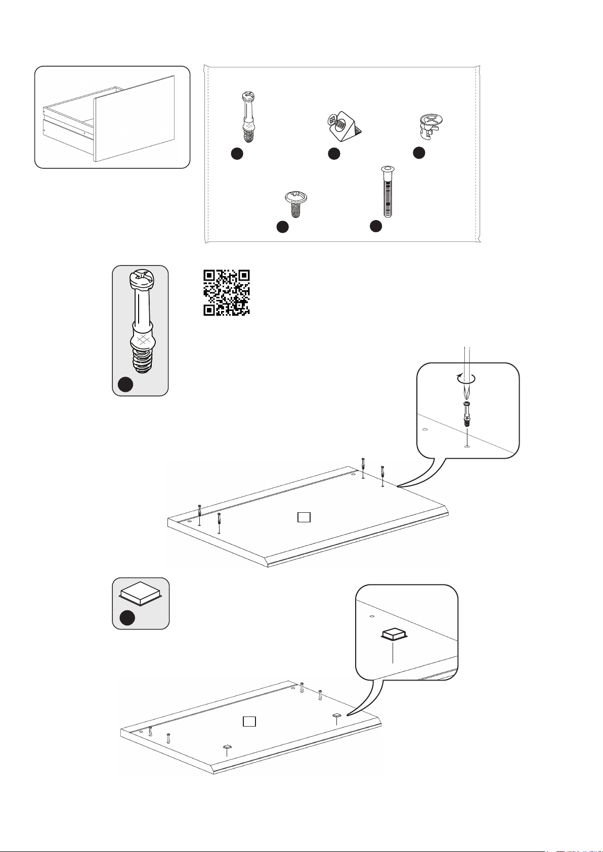
Drawer Assembly
x 2
43
Bag 2
F901
B
x 8
N
x 4
Drawer Assembly
www.youtube.com/watch?v=InNBV_uuMmo
I
F74
x 8
F639
O
x 8
M
F171GY
x 8
F607
44
B
x 8
13
K
x 4
x 2
13
x 2
Page 29
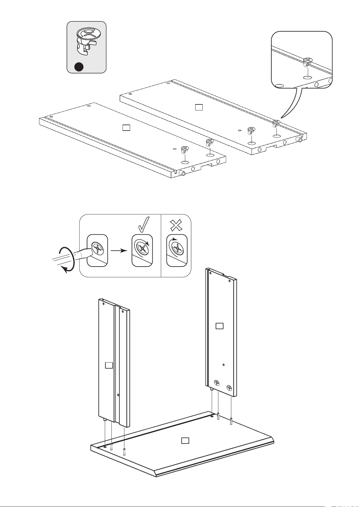
45
M
x 4
15
14
x 2
x 2
46
x 4
14
15
13
x 2
Page 30
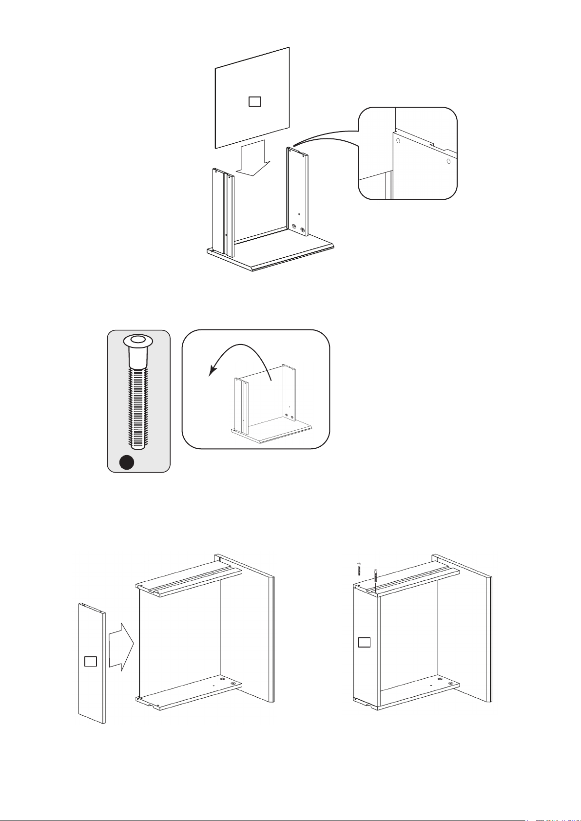
47
16
x 2
48
O
x 4
17
17
x 2 x 2
Page 31
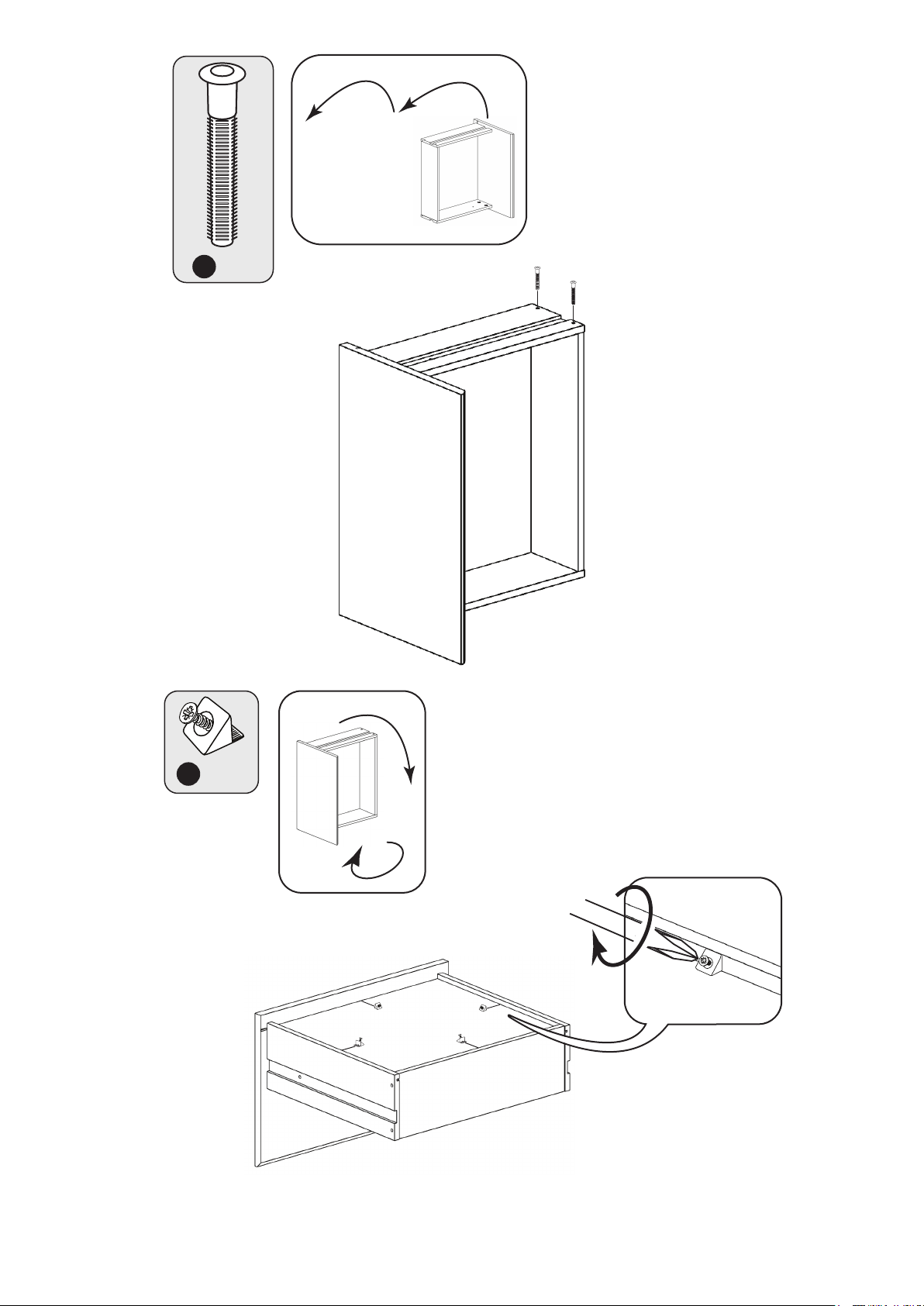
49
O
x 4
50
x 2
I x 8
x 2
Page 32
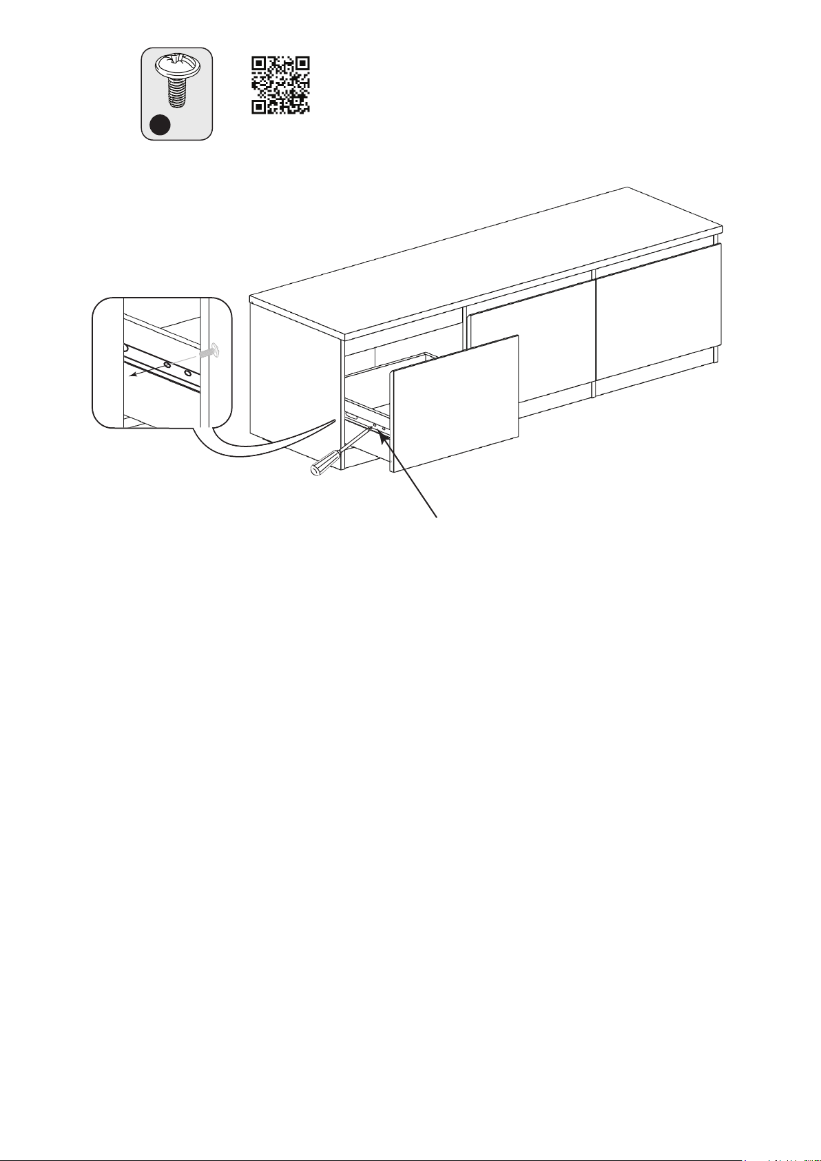
51
Fitting Ball Bearing Runners
www.youtube.com/watch?v=yG4xtiJJeSg
N
x 4
Warning: Use a Screwdriver
to position the Runners as
they could have sharp edges
Slide both of the Runners forward and locate the Drawer Sides between them, lining up the
holes in the Drawer Sides with the 2nd 'threaded' holes in the Runners.
Working from the inside of the Drawer, insert 2 Screws through the Drawer Sides and out into
the 2nd threaded hole in the Runner.
Note: Do not overtighten the Screws.
If they catch on the runner you may need to loosen them slightly.
Assembly is complete
Please remove any blue protective film from panel
edges and clear protective film from panel surfaces
ALR3717
 Loading...