

Page 1

Arlo 3 Drawer Wardrobe White-Pine
Assembly Instructions - Please keep for future reference
8791335
Dimensions
Length - 78cm
Depth - 53cm
Height - 180cm
Weight - 67kg
Important – Please read these instructions fully before starting assembly
If you need help or have damaged or missing parts, call the Customer Helpline:
0045 7668 8055 or e-mail: order@fl exa.dk
Issue 1 - 26/11/18
Page 2

Safety and Care Advice
Important – Please read these instructions
fully before starting assembly
• Check you have all the
components and tools listed on
pages 2, 3 and 4.
• Remove all fi ttings from the
plastic bags and separate them
into their groups.
• During assembly children
should be kept away from the
product due to possible risk of
injury.
• Make sure you have enough
space to layout the parts before
starting.
Care and maintenance
• Only clean using a damp cloth
and mild detergent, do no use
bleach or abrasive cleaners.
• Regularly check all fastenings
to ensure that they properly
tightened.
• Do not stand or put weight on
the product, this could cause
damage.
• Assemble the item as close
to its fi nal position (in the same
room) as possible.
• Assemble on a soft level
surface to avoid damaging the
unit or your fl oor.
• Parts of the assembly will be
easier with 2 people.
• Do not use this item if any
components are missing or
damaged
• This product should not be
discarded with household waste.
Take to your local authority
waste disposal centre.
• We do not
recommend the
use of power
drill/drivers for
inserting screws,
as this could
damage the unit. Only use hand
screwdrivers.
• Dispose of all packaging
carefully and responsibly.
• Assembly to be carried out by
a competent adult only.
• This product is suitable for
children in the age 4-12 years.
Maximum load in each drawer
7 kg.
1
Page 3
If you have damaged or missing components,
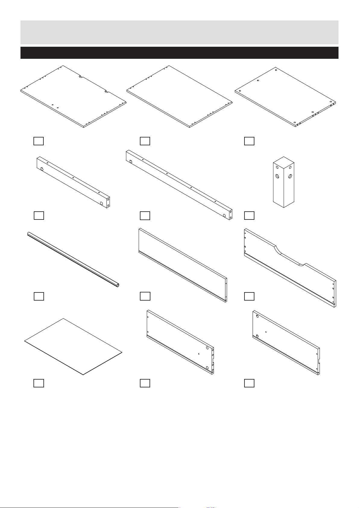
Components - Parts
call the Customer Helpline: 0045 7668 8055
Please check you have all the parts listed below
Top x1
1
(78.0x53.0x1.6cm)
No. 4301-1607803-40
Plinth side x2
4
(43.4x5.0x1.9cm)
No. 12-01904341
Hanging rail x1
7
(74.1x2.2x1.5cm)
No. 3946-0741-2
Base x1
2
(78.0x53.0x1.6cm)
No. 4301-1607804-40
Plinth front x2
5
(68.4x5x1.9cm)
No. 12-01906841
Drawer back x3
8
(71.6x16.7x1.3cm)
No. 15-01307161
Shelf x2
3
(74.8x50.2x1.6cm)
No. 4301-1607486-40
Leg x4
6
(14x4.3x4.3cm)
No. 12-04301401
Drawer front x3
9
(74.4x18.5x1.6cm)
No. 4301-1607445-40
Drawer base x3
10
(72.8x48.3x0.3cm)
No. 4309-0307282
Drawer side Right x3
11
(48.8x16.7x1.3cm)
No. 15-01304881
Drawer side Left x3
12
(48.8x16.7x1.3cm)
No. 15-01304882
2
Page 4
If you have damaged or missing components,
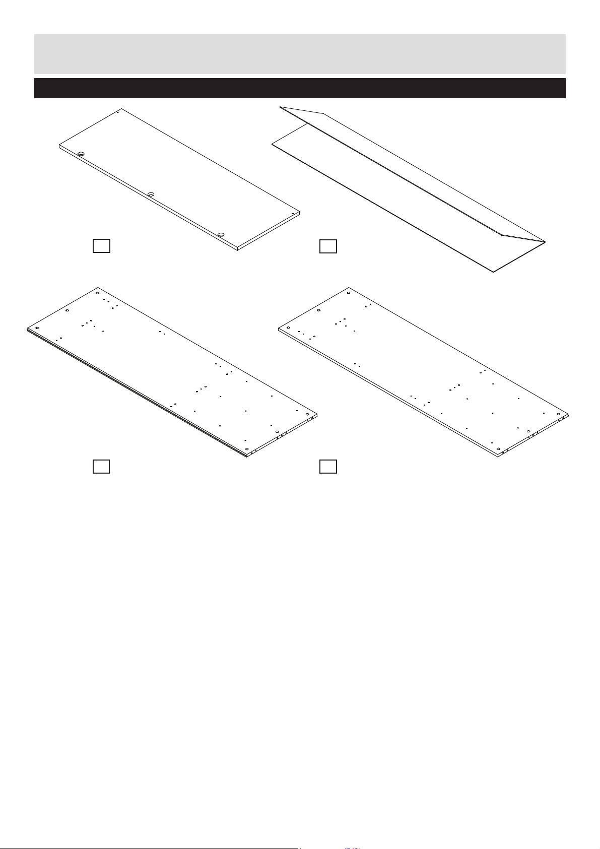
Components - Parts
call the Customer Helpline: 0045 7668 8055
Please check you have all the parts listed below
Door x2
13
(105.8x37x1.6cm)
No. 4301-1610581-40
Side panel Right x1
15
(162.8x52.6x1.6cm)
No. 4301-1616281-40 No. 4301-1616282-40
Back panel x1
14
(164.7x76.6x0.3cm)
No. 4309-0316471
Side panel Left x1
16
(162.8x52.6x1.6cm)
3
Page 5
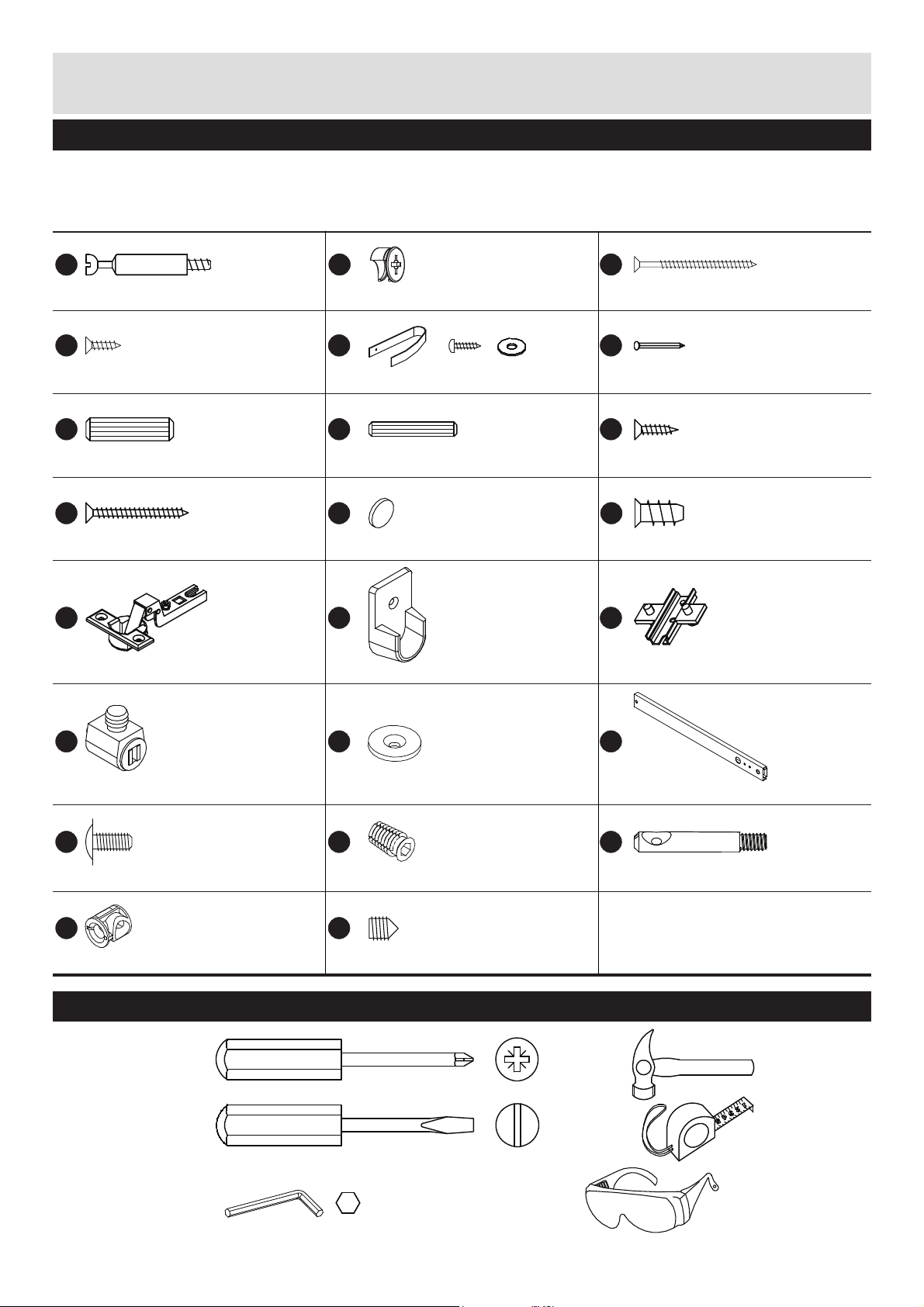
Components - Fittings
Please check you have all the fi ttings listed below
Note: The quantities below are the correct amount to complete the assembly. In some cases more fi ttings
may be supplied than are required.
No. 3933-15010No. 4020-005
A
7x34mm for ø5 Minifi x bolt x36
No. 3901-30012
D
3.0x12mm Chipboard screw x4
No. 3930-08030 No. 3930-05030
G
8x30mm Dowel x36 5x30 mm Dowel x16
No. 3901-35035
J
3.5x35mm Chipboard screw x12
No. 4015-007 No. 4015-008
M N
Ø26 mm Cup hinge x6 Mounting plate x6
No. 4012-012
B
ø15x9.5mm Minifi x cam x36
No. 41-00179
E
Overbalance protector x2
H
No. 4026-022
K
Door bumper x2
No. 4038-003-2
Hanging rail fi tting x2
No. 4012-010
C
4.0x60mm Chipboard screw x14
F
1.6x16mm Nail square x48
I
3.5x15mm Chipboard screw x12
L
ø5.8x11mm Euro screw x18
O
No. 3901-40060
No. 4022-004
No. 3901-35015
No. 3907-58011
No. 4010-028
P
Magnetic catch x2
No. 3912-04009
S
Ø9.5/M4x9mm Machine screw x6
No. 3933-14015
V W
Tools required
Phillips
screwdriver
(medium)
Flatblade
screwdriver
(medium)
Allen key
6mm incl.
No. 4033-010
Q
Counter plate x2
No. 4028-021
T
M6/Ø12x20mm Threaded bush x8
No. 3917-08009
M8x8,5mm Grub screw x8Ø14x14,5mm Threaded bush x8
R
438x27x10mm Drawer slide x6
No. 4020-022
U
Ø7x45mm Connecting bolt x8
Small
hammer
Ruler/tape
measure
Eye protection
(when using a
hammer or glue)
4
Page 6

Assembly Instructions
Step 1
Screw the threaded
T
bushes
into the leg 6
using 6mm allen key so
that they are fl ush with
the leg.
Screw the connecting
U
bolts
bushes
into the threaded
T
.
Repeat for 4 legs.
Step 2
Insert the dowels
the holes in the plinth
5
fronts
sides
and the plinth
4
.
G
into
U
G
T
T
6
U
G G
T
U
G
G
It may be necessary
to tap the dowels in
very gently with a small
hammer.
Step 3
Assemble the plinth.
Push threaded bushes
V
into the holes in the
5
plinth fronts
plinth sides
Attach the plinth fronts
5
and the plinth sides
4
to the legs 6 by
placing the dowels into
the holes in legs
connecting bolts into
the holes in the plinth
5
fronts
sides
4
Fasten the legs
and the plinth fronts
5
and the plinth sides
4
by tightening the
grub screws
threaded bushes
and the
4
.
6
and
and the plinth
.
6
W
in the
V
.
4
G
G
G
4
G
5
5
V
W
5
6
4
6
6
4
6
5
6
5
W
NB!
4
V
Don’t overtighten.
5
Page 7

Assembly Instructions
Step 4
Attach the assembled
2
plinth to the base
with
the chipboard screws
NB! Align the holes in
4
plinth sides
with the
small holes in base
Step 5
Attach minifi x bolts A
1
to the top
base
2
and to the
.
C
C
C
.
2
.
6 HOLES UP!
C
4
2
C
4
C
A
A
P
Attach magnetic catches
P
to the top 1.
It may be necessary to
tap the magnetic catches
P
in very gently with
small hammer.
Step 6
G
Insert the dowels
the holes in the shelfs
3
.
It may be necessary
to tap the dowels in
very gently with a small
hammer.
into
G
1
A
3
P
A
2
G
A
G
G
G
3
6
Page 8

Assembly Instructions
Step 7
Insert the dowels H to
the holes in the side
15
panels
Attach minifi x bolts
the side panels
16
.
Attach the hanging rail
fi ttings
panels
screws
Attach the hinge
mounting plates
side panels
Attach the drawer
runners
panels
euro screws
Be aware of the front
edge!
and 16.
15
N
to the side
15
and 16 with
D
.
15
and 16.
R
to the side
15
and 16 with
L
.
A
and
O
to the
to
A
H
O
Front edge
H
O
O
N
R
L
D
H
H
H
A
A
A
D
N
A
H
H
H
H
A
D
N
O
A
O
BACK
16
FRONT
15
Front edge
O
H
16
A
R
A
A
L
L
L
L
L
L
H
H
L
L
L
H H
R
R
A
L
L
L
15
Front edge
A
L
L
L
H
O
A
L
L
L
H
NB! 3rd hole
L
H
R
Front edge
R
L L
7
Page 9

Assembly Instructions
Step 8
Attach the side panels
15
and 16 to the shelfs
3
with the minifi x cams
B
.
Be aware of the front
edges!
B
16
3
15
Front edge
3
16
3
B
Step 9
1
Attach the top
the base
panels
2
15
and 16 with
the minifi x cams
Be aware of the front
edges!
and
to the side
B
.
B
1
1
15
Front edge
B
16
2
16
8
Page 10

Assembly Instructions
Step 10
Attach the back panel 14
F
with nails
side of the wardrobe.
Nail the back panel
the carcass around the
edge ensuring that there
are NO GAPS between
the top
panel
measurements.
Nail the back panel
to the bottom shelf
Follow the measurement
606 mm from the
underside of the base
Be careful.
to the back
1
and the back
14
. Follow the
14
14
3
to
.
2
60 mm
F
60 mm
60 mm
606 mm
3
F
14
2
606 mm
Step 11
Attach the hinges
to both doors
screws
13
I
.
M
using
60 mm
2
I
M
I
M
13
I
M
I
M
I
13
I
M
I
M
M
9
Page 11

Assembly Instructions
Step 12
Insert the dowels G into
the holes in the drawer
11
sides
and 12.
Attach the minifi x bolts
9
to the drawer front
.
Repeat for all drawer
sides and drawer fronts.
Step 13
Attach the drawer sides
11
and 12 to the drawer
9
front
cams
Repeat for all drawers.
with the minifi x
B
.
A
G
A
12
11
A
A
G
G
A
A
9
B
B
9
B
12
Step 14
Push the drawer base
carefully into the drawer.
Attach the drawer back
8
to the drawer sides
11
and 12 with the
J
screws
.
Repeat for all drawers.
10
B
B
11
J
J
J
11
9
12
10
8
J
J
10
Page 12

Assembly Instructions
Step 15
Measure out the
positions for the wall
attachment straps.
Drill two holes spaced
as illustrated with the
appropriate size for the
wall attachment fi tting
(see next step).
Pull the two straps
through the gaps in
1
top plate
furniture against the wall
and secure the strap
under the top plate with
washer and screw.
.Push the
E
E
320 mm
1
E
Step 16
Different types of wall
fi ttings. Contact your
local DIY or hardware
store for the wall plugs
and screws.
1775 mm
E
Concrete/Brick wall
Plaster wall
11
Wooden wall
Page 13

Assembly Instructions
Step 17
Place the assembled
drawer between the
R
drawer runners
Attach the drawer sides
11
and 12 to the runners
using the screws
Repeat for all drawers.
Place the hanging rail
7
into the hanging rail
N
fi ttings
.
Attach the doors with
the hinges
M
mounting plates
Attach counterplates
to both doors
D
screws
.
Put the door bumpers
on the edge of the lower
shelf
3
.
.
S
to the
O
13
using
.
.
Q
K
S
Q
D
K
D
Q
O
13
M
13
3
Assembly is complete.
This drawer must be positioned furthest from floor level
WARNING!
IN ORDER TO PREVENT OVERTURNING
THIS PRODUCT MUST BE USED WITH
THE WALL ATTACHMENT DEVICE
PROVIDED
Serious or fatal crushing injuries can occur from
furniture tipping over. To help prevent topple over:
• Use the wall attachment device provided
• Never allow children to climb or hang on
drawers, doors or shelves
• Place heaviest items in the lower drawers
or shelves
• Unless specifically designed to
accommodate, do not set TV's or other
heavy objects on top of this product
• Never open more than one drawer at a
time
An attachment device is provided with your product,
however you will need to source suitable fixings for your
wall type. If in doubt, please consult a qualified
trades person.
Always ensure the wall to be drilled is free from hidden
electrical wires, water and gas pipes.
Permanent safety label. Please do not remove
K
11
S
7
S
12
R
N
If you need help or have damaged or missing parts,
call the Customer Helpline: 0045 7668 8055
E-mail: order@fl exa.dk
Ref.no. 44-01832-09 A Stand: 261118 Page 13 (81-33504-09)
12
Page 14

 Loading...