

Page 1
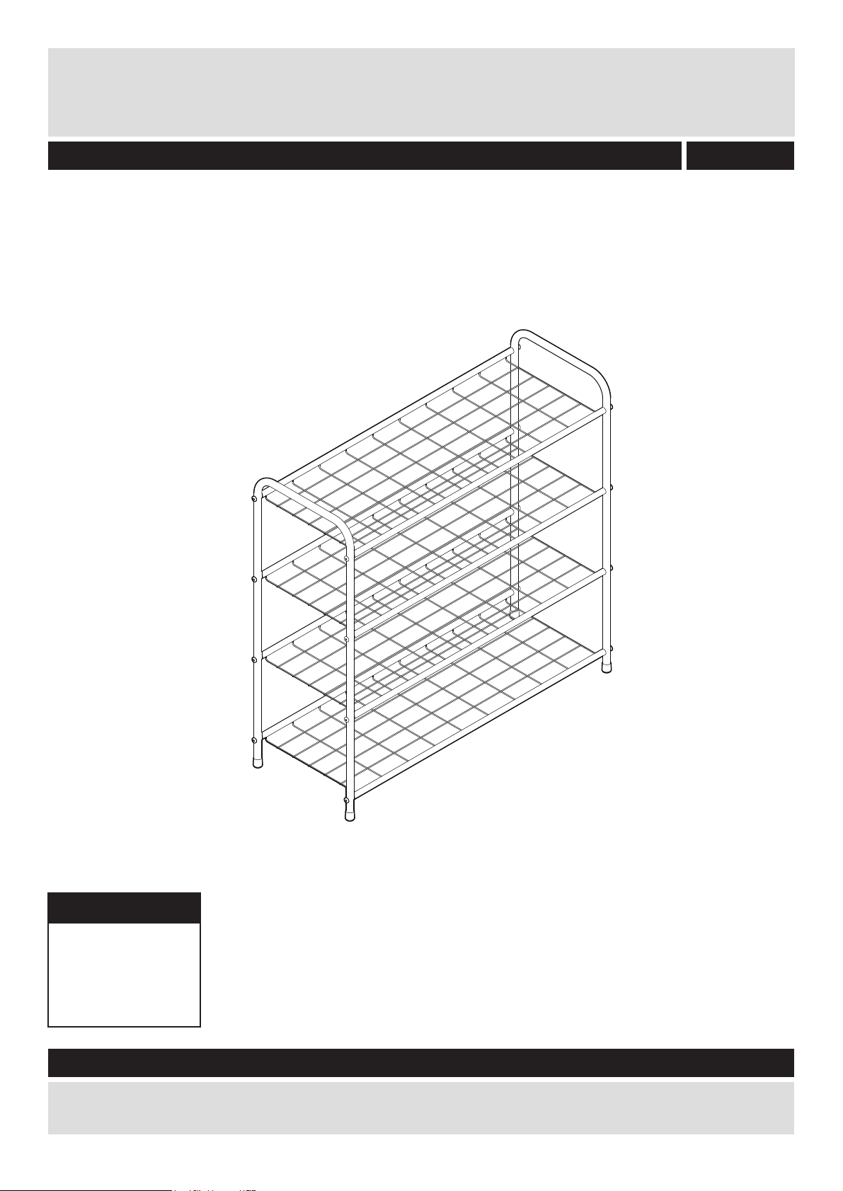
4 Tier White Shoe Rack
Assembly Instructions - Please keep for future reference
875/5429
Dimensions
Width - 75cm
Depth - 28cm
Height - 73cm
Important - Please read these instructions fully before starting assembly
If you need help or have damaged or missing parts, call the
Customer Helpline: 08456 400800
Page 2

Safety and care advice
Important - Please read these instructions fully before starting assembly
• Check you have all the
components and tools listed on
pages 2 and 3.
• Remove all fittings from the
plastic bags and separate them
into their groups.
• Keep children and animals
away from the work area, small
parts could choke if swallowed.
• Make sure you have enough
space to layout the parts before
starting.
Care and maintenance
•Only clean using a damp cloth
and mild detergent, do no use
bleach or abrasive cleaners.
• Assemble on a soft level surface
to avoid damaging the unit or your
floor.
• Parts of the assembly will be
easier with 2 people.
• If using power tools, please
follow the safety instructions
supplied with the tools.
• Assemble the unit as close to its
final position (in the same
room) as possible.
• From time to time check that
there are no loose screws on
this unit.
• We do not
recommend the use
of power drill/ drivers
for inserting screws,
as this could damage
the unit.
Only use hand screwdrivers.
• Dispose of all packaging carefully
and responsibly.
• This product should not be
discarded with household waste.
Take to your local authority
waste disposal centre.
1
Page 3
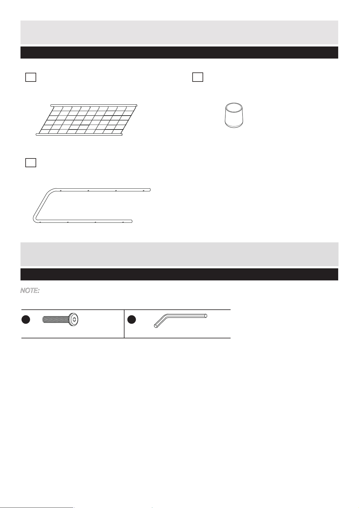
Components - Panels
If you have damaged or missing components,
call the Customer Helpline: 08456 400800
Please check you have all the panels listed below
Net x 4
1
Side support x 2
2
3
PP cap x 4
Components Fittings
Please check you have all the fittings listed below
NOTE: The quantities below are the correct amount to complete the assembly. In some cases more
fittings may be supplied than are required.
A
32mm screw x 16
B
Allen key x 1
2
Page 4
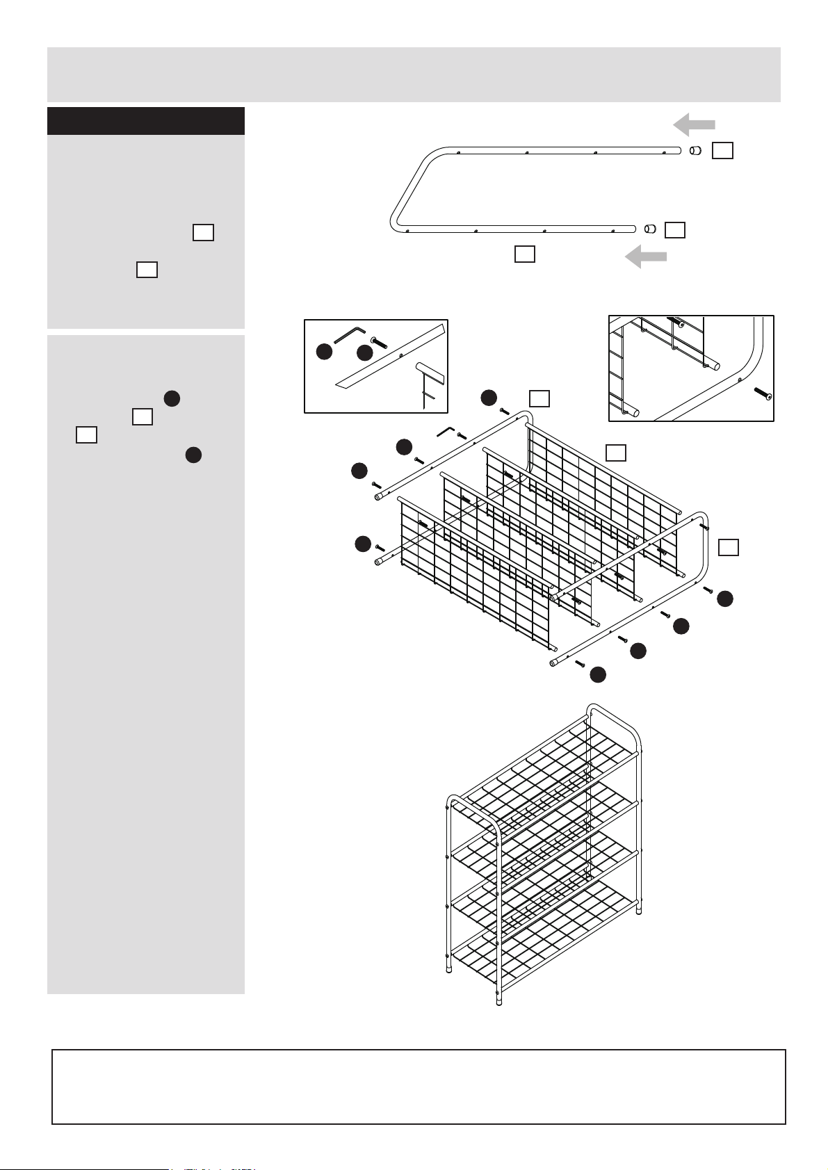
Assembly Instructions
Step 1
a:
NOTE: It would be useful
to ask someone to help
you at this stage.
3
A
A
B
A
2
b:
B
A
fig.1
A
A
A
A
a: Inset the PP cap
into the end of Side
2
support .
2
b: Attch Screw to Side
2
support and Net
1
1
, and tighten by
2
using Allen key as
shown in fig.1 and
fig.2 .
A
A
A
A
3
2
3
2
2
2
2
2
fig. 2
1
1
The assembly is complete.
A
A
A
A
A
A
A
A
2
2
A
A
If you need help or have damaged or missing parts, call the
Customer Helpline: 08456 400800
3
 Loading...