

Page 1
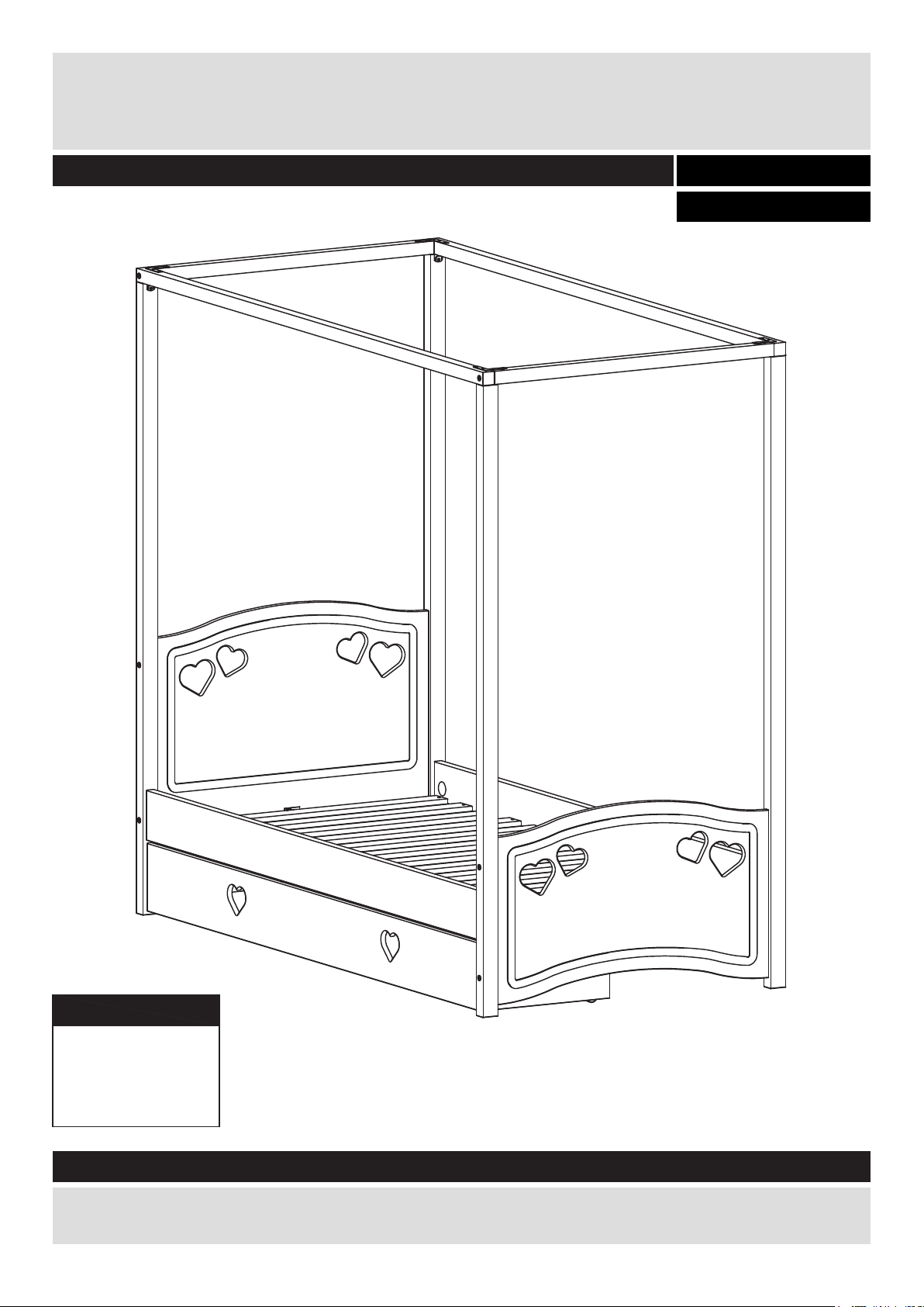
Mia 4 Poster Bed
Assembly Instructions - Please keep for future reference
White 2627436
Pink 2557386
Dimensions
:
Width
Depth
Height
197.3 cm
:
99.5 cm
:
186.2 cm
Assembly Instructions - Please keep for future reference
If you need help or have damaged or missing parts, call the Argos Customer Helpline: 0845 640 30 30
350268-01
Issue 1 - 26-05-2014
Page 2
Safety and Care Advice
!
Important - Please read these instructions fully before starting assembly
• Check you have all the
components and tools listed on
pages 2 and 3.
• Remove all fittings from the
plastic bags and separate them
into their groups.
• Keep children and animals
away from the work area, small
parts could choke if swallowed.
• Make sure you have enough
space to layout the parts before
starting.
Care and maintenance
• Only clean using a damp cloth
and mild detergent, do no use
bleach or abrasive cleaners.
• Do not stand or put weight on
the product, this could cause
damage.
• Assemble the item as close to
its final position (in the same
room) as possible.
• Assemble on a soft level
surface to avoid damaging the
unit or your floor.
• Parts of the assembly will be
easier with 2 people.
• From time to time check that
there are no loose screws on
this unit.
• We do not recommend the use
of power drill/drivers for
inserting screws, as this could
damage the unit. Only use hand
screwdrivers.
• Dispose of all packaging
carefully and responsibly
• This product should not be
discarded with household waste.
Take to your local authority
waste disposal centre.
.
Note !
• This childs bed conforms to BS 8509:2008 +A1:2011.
• Age recommendation: from 3 year to 12 years.
• Mattress in size 90x190 cm to be used with this bed.
• Children are likely to play, bounce ,jump and climb on beds, therefore the childs bed should not
be placed too close to other furniture or windows, and should be placed either tight to any wall or
have a gap 300mm between the wall and the side of bed.
• Any additional or replacement parts are obtained from the manufacturer or distributor.
Note: if required the next
page can be cut out and used
as reference throughout the
assembly. Keep this page
with these instructions for
future reference.
1
Page 3
If you have damaged or missing components, call
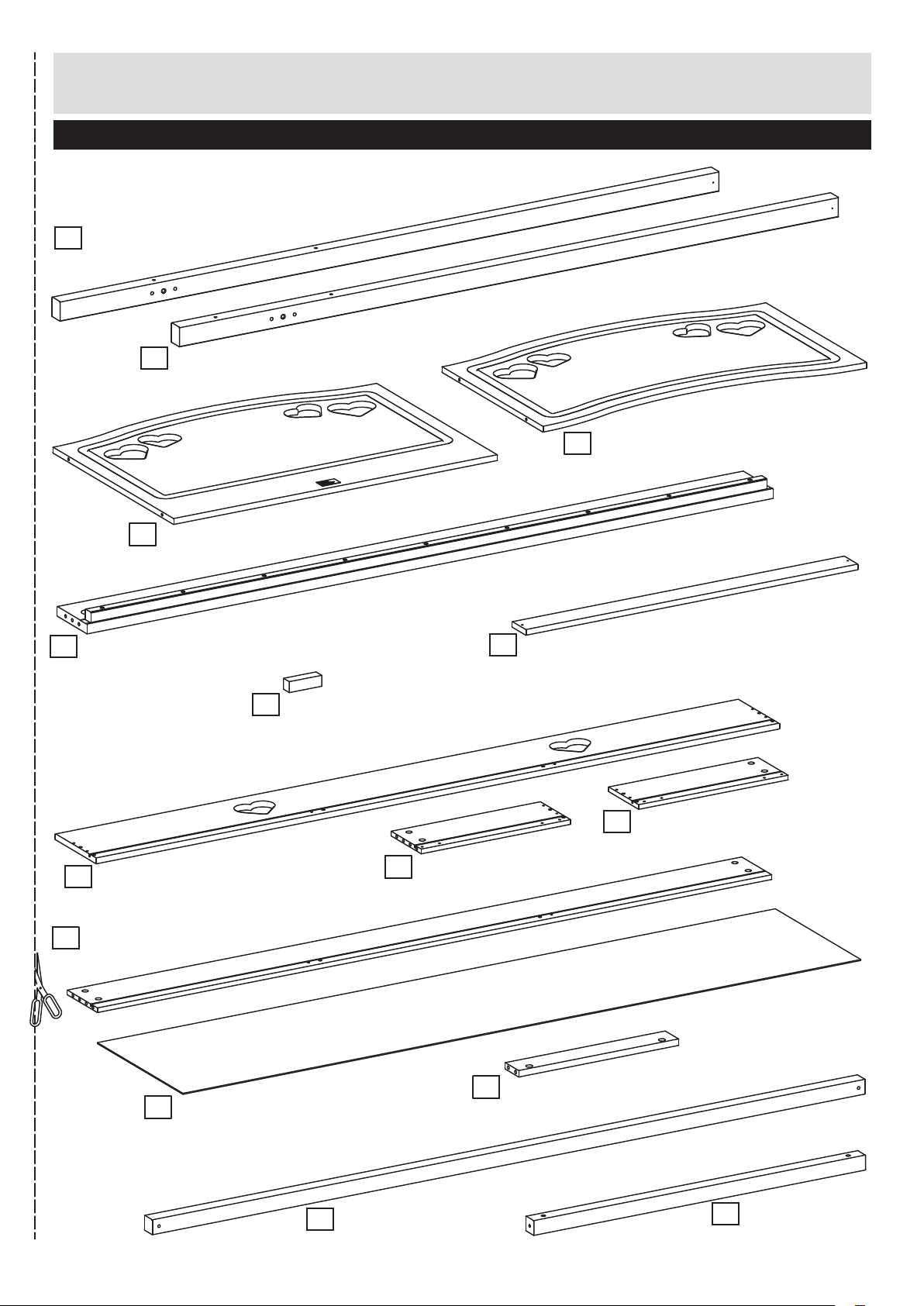
Components - Panels
the Argos Customer Helpline: 0845 640 30 30
Please check you have all the panels listed below
1
Post, headboard
(182,4 cm x 5 cm)
3
5
Side rail
(189,7 cm x 14,5 cm)
x
x
2
2
Post, foot
(182,4 cm x 5 cm)
Headboard
(89,5 cm x 64 cm)
2
7
Slat
(91,8 cm x 6,8 cm)
4
Footboard
(89,5 cm x 54,5 cm)
8
Drawer front
(189,1 cm x 19,7 cm)
Drawerback
11
(186,5 cm x 14,5 cm)
12
Drawer bottom
(187,5 cm x 41,0 cm)
6
Spacer block
(7,1 cm x 2,2 cm)
9
Drawerside, left
(41,3 cm x 14,5 cm)
13
Drawer rail
(40,0 cm x 6 cm)
x
10
Drawerside, right
(41,3 cm x 14,5 cm)
2
350268-03
Top rail, side
14
(197,3 cm x 3,8 cm)
x
15
2
Top rail, end
(91,9 cm x 3,8 cm)
x
2
2
Page 4
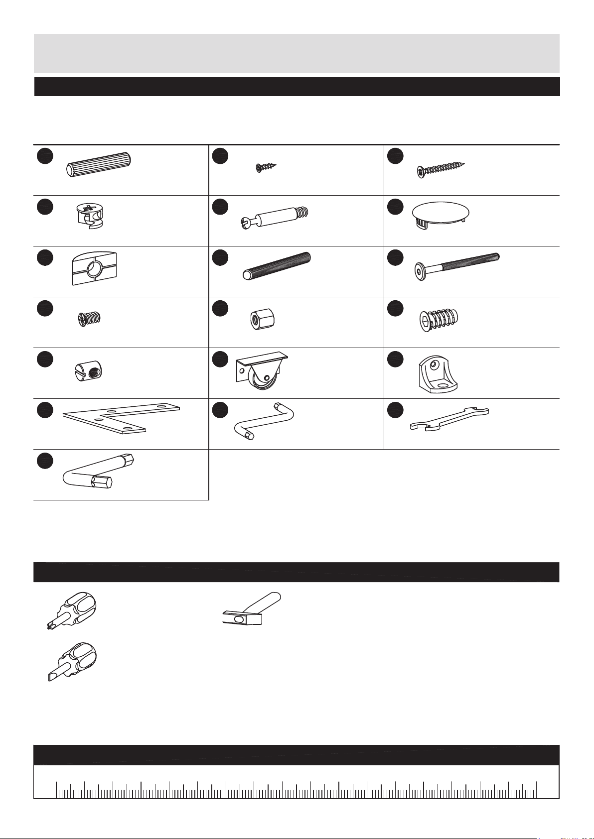
Components - Fittings
Please check you have all the panels listed below
Note: The quantities below are the correct amount to complete the assembly. In some cases more ttings
may be supplied than are required.
Aa
ø7.8 x 40mm Wooden dowel x
Ca
ø15 x 10.5mm Cam x
Fm
ø35mm Bracket x
Ke
ø6.1 x 11.5mm Screw x
Nf
M6, ø10 x 12.5mm barrel nut x
Vq
70 x 70 x 16mm Corner angle x
12
4
8
12
4
20
Bo
ø3 x 12mm Screw x
Cb
ø5 x 8, cc34mm Bolt x
Hg
M6 x 70mm Threaded rod x
Na
M6 x 10mm Nut x
ø35mm Wheel xTa4
4mm Allen key xYa1
24
12
4
Bv
ø3,5 x 30mm Screw x
Ec
ø35mm Cap x
Hw
4
M6 x 80mm Bolt x
Ne
M6 x 20mm Bushing x
Vn
Angle 23 x 23 x 24mm x
Yb
10/13mm Wrench x
4
28
12
4
4
1
6mm Allen key xYc1
Tools required
Phillips screwdriver
(Medium & large)
Flatblade screwdriver
(Medium)
Hammer
Ruler - Use this ruler to help correctly identify the screws
17060 16040 90 15013070 120100 14011050 803020100
3
350268-04
Page 5
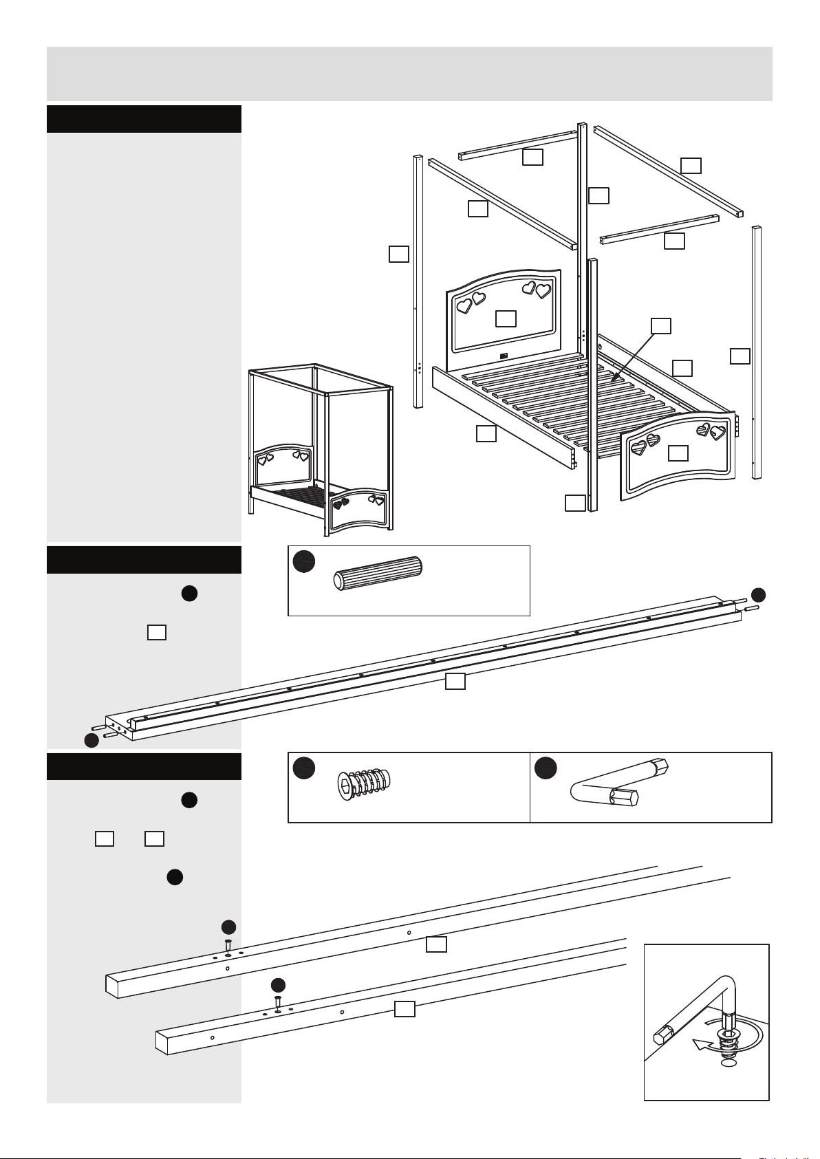
Assembly Instructions
Step 1
Assembly of the bed.
15
1
14
1
3
5
2
14
15
x
14
7
5
4
2
Step 1.1
Knock the dowels Aa into
the holes indicated on
5
the side rails
small hammer.
Aa
using a
Step 1.2
Screw the bushings Ne into
the holes indicated on the
1
posts
Use the allen key
and 2.
Yc
.
Ne
Aa
ø7.8 x 40mm Wooden dowel x
5
Ne
M6 x 20mm Bushing x
4
1
x
2
x
8
2
6mm Allen key xYc1
Aa
350268-05
Ne
2
x
2
4
Page 6

Assembly Instructions
Step 1.3
Fix the posts 1 onto the
3
headboard
Hw
into the barrel nuts Nf.
Note - the holes in the posts
for the siderails must point
downwards.
Fix the posts
footboard
into the barrel nuts
using bolts
2
onto the
4
using bolts Hw
Nf
.
1
Hw
Hw
M6 x 80mm Bolt x
8
Note NO holes !
The holes for the
siderails on reverse side !
Nf
Nf
Hw
Nf
M6, ø10 x 12.5mm barrel nut x
8
Ya
4mm Allen key x
1
1
Nf
3
Nf
Hw
Hw
Make sure to place the legs
2
onto the footboard 4
exactly as shown. Note the
holes for the siderails must
point upwards.
Ya
Use the allen key
.
Note the holes for
the siderails !
2
Hw
Hw
Nf
2
Nf
Hw
Hw
Nf
4
Nf
Nf
Hw
5
350268-06
Page 7

Assembly Instructions
Step 1.4
Screw the threaded rods
Hg
into the bushings Ne in
1
the posts
Fix the angles
posts
screws
indicated.
Bo
Vn
and 2.
Vn
to the
1
and 2 using
Bo
into the holes
Bo
ø3 x 12mm Screw x
4
Vn
Angle 23 x 23 x 24mm x
Hg
M6 x 70mm Threaded rod x
4
Bo
Vn
4
Vn
Bo
1
Hg
1
Hg
Bo
Vn
2
Hg
350268-07
2
Hg
6
Page 8

Assembly Instructions
Step 1.5
Place the side rails
onto the headboard
1
posts
.
Push the brackets
the nuts
Na into the holes
indicated on the side rails
5
and onto the threaded
Hg
rods
.
Tighten the nuts
the wrench
Fm
5
Fm
and
Na using
.
Fm
ø35mm Bracket x
2
Na
M6 x 10mm Nut x
2
Yb
10/13mm Wrench x
1
1
1
Hg
Fm
Na
Fm
Na
5
Produced by:
NJA Furniture A/S
DK-7700 Thisted
Safety requirements:
EN BS 8509:2008+A1:2011
Prod. wk/year: xx/201x
7
5
350268-08
Page 9

Assembly Instructions
Step 1.6
Place the footboard posts
2
onto the side rails 5.
Fm
.
Fm
and
Na using
Push the brackets
the nuts
Na into the holes
indicated on the side rails
5
and onto the threaded
Hg
rods
.
Tighten the nuts
the wrench
Ec
ø35mm Cap x
4
Na
M6 x 10mm Nut x
2
Fm
ø35mm Bracket x
Yb
10/13mm Wrench x
1
2
2
2
Fm
Na
Insert the caps Ec
into
the holes indicated on
5
the side rails
.
Hg
5
5
Fm
Na
350268-09
Ec
8
Page 10

Assembly Instructions
Step 1.7
Fix the top rails (side) 14 to
15
the toprails (end)
Hw
bolts
nuts
into the barrel
Nf
.
Use the allen key
Nf
Hw
using
Ya
.
Hw
M6 x 80mm Bolt x
Nf
15
14
Nf
4
M6, ø10 x 12.5mm barrel nut x
4
Ya
4mm Allen key x
Hw
1
14
Nf
Hw
Nf
15
Step 1.8
Fix the corner angles Vq
to the upper side of the top
Bo
frame using screws
Note !
The holes for the
barrel nuts in the end rail
15
must point upwards
.
Bo
Vq
Hw
Bo
ø3 x 12mm Screw x
Vq
16
Bo
Vq
70 x 70 x 16mm Corner angle x
Bo
4
Vq
Bo
Vq
14
Vq
15
9
350268-10
Page 11

Assembly Instructions
Step 1.9
Place the top frame on the
top of the posts.
Fix it using screws
through the angles
Bo
Vn
.
Bo
15
14
Bo
ø3 x 12mm Screw x
15
14
15
4
14
Vn
Bo
350268-11
10
Page 12

Assembly Instructions
Step 1.10
Fix the rst of the slats 7
to the slatholders using
Bv
screws
The slats
distributed evenly in the
bedframe. To get the
distance right use the
spacer block
See detail.
.
7
must be
6
as shown.
Bv
Bv
ø3,5 x 30mm Screw x
6
7
Bv
2
7
Step 1.11
Fix the second of the slats
7
to the slatholders using
Bv
screws
To get the distance right
use the spacer block
shown.
See detail.
.
6
as
Bv
Bv
ø3,5 x 30mm Screw x
7
Bv
7
2
6
7
11
350268-12
Page 13

Assembly Instructions
Step 1.12
Fix the rest of the slats 7
Bv
using screws
To get the distance right
use the spacer block
shown.
See detail.
.
6
as
Bv
ø3,5 x 30mm Screw x
24
Bv
7
7
6
7
Bv
7
350268-13
12
Page 14

Assembly Instructions
Step 2
Assembly of the drawer.
9
12
13
8
13
11
10
Step 2.1
Screw the bolts Cb into
the holes indicated on the
11
drawer back
drawer sides
and the
9
and 10.
Knock the dowels Aa into
the holes indicated on
drawer back 11, the
the
9
drawer sides
and 10
and the
Aa
13
drawer rails
using a
smal hammer.
Step 2.2
Aa
ø7.8 x 40mm Wooden dowel x
Aa
Cb
13
11
9
Aa
Ke
12
Cb
Cb
ø5 x 8, cc34mm Bolt x
Aa
Cb
Cb
Ta
6
Aa
10
Aa
Fix the wheels Ta onto
the drawer sides 9 and
10
using screws Ke.
See detail.
13
ø6.1 x 11.5mm Screw x
8
9
Ta
Ke
Ke
ø35mm Wheel x
Ke
Ta
Ke
Ta
4
10
Ke
Ta
350268-14
Page 15

Assembly Instructions
Step 2.3
Screw the bolts Cb into
the holes indicated on
8
the drawer front
Cb
.
Step 2.4
Push the drawer sides 9
10
and
rails
back
Place cams
holes indicated. Arrow
pointing towards the front.
Turn the cams
right to x the drawer
back.
and the drawer
13
onto the drawer
11
.
Ca
into the
Ca
to the
Cb
ø5 x 8, cc34mm Bolt x
Cb
Ca
ø15 x 10.5mm Cam x
Cb
6
Cb
8
6
10
13
Ca
Ca
13
11
Ca
Step 2.5
Slide the drawer bottom
12
into the drawer
9
sides
and 10.
9
Ca
12
10
9
350268-15
14
Page 16

Assembly Instructions
Step 2.6
Push the drawer front 8
onto the drawer sides
10
and
rails
and the
13
.
drawer
Place cams Ca into the
holes indicated. Arrow
pointing towards the front.
Ca
Turn the cams
to the
right to x the front.
9
Ca
ø15 x 10.5mm Cam x
6
Ca
8
10
Ca
Ca
Ca
13
13
9
Step 2.7
Place the drawer.
15
350268-16
 Loading...