

Page 1
Assembly Instructions
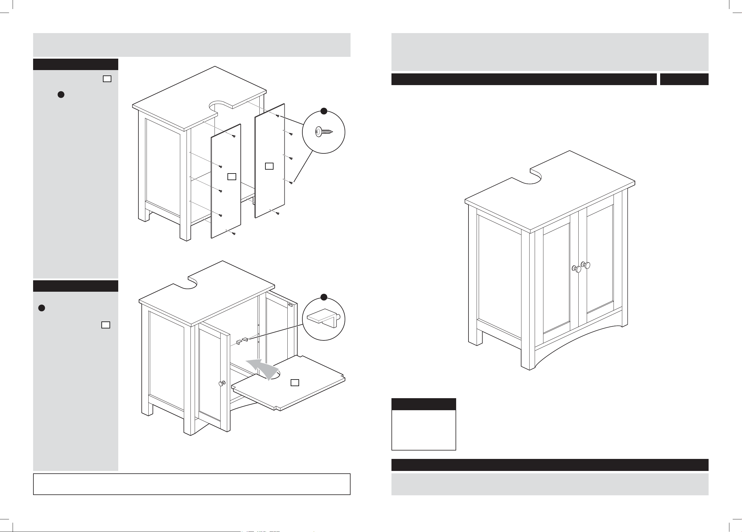
Step 9
Under Basin Storage Unit
Connect back panels
using 10 x back panel
screw E as shown.
8
E
8
8
Assembly Instructions- please keep for future reference
833/2811
Step 10
Insert 4 x shelf bracket
L
inside the unit at the
desired height as shown
and set internal shelf
in place.
Assembly complete.
9
L
9
Dimensions
Width - 48cm
Depth - 30cm
Height - 60cm
If you need help or have damaged or missing parts, call the Customer Helpline: 0845 640 0800
Important – Please read these instructions fully before starting assembly
If you need help or have damaged or missing parts, call the Customer Helpline: 0845 640 0800
Issue 1 - 01/09/10
Page 2
Safety and Care Advice
Components - Panels
Important – Please read these instructions fully before starting assembly
• Check you have all the
components and tools listed on
pages 1 and 2.
• Remove all ttings from the
plastic bags and separate them
into their groups.
• Keep children and animals
away from the work area, small
parts could choke if swallowed.
• Make sure you have enough
space to layout the parts before
starting.
• Do not stand or put weight on
the product, this could cause
damage.
• Assemble the item as close
to its nal position (in the same
room) as possible.
• Assemble on a soft level
surface to avoid damaging the
unit or your oor.
• Parts of the assembly will be
easier with 2 people.
• We do not
as this could damage the unit.
Only use hand screwdrivers.
• Dispose of all packaging
carefully and responsibly.
Care and maintenance
• Only clean using a damp
cloth and mild detergent, do
not use bleach or abrasive
cleaners.
• From time to time check that
there are no loose screws on
this unit.
• This product should not be
discarded with household
waste. Take to your local
authority waste disposal
centre.
recommend the
use of power
drill/drivers for
inserting screws,
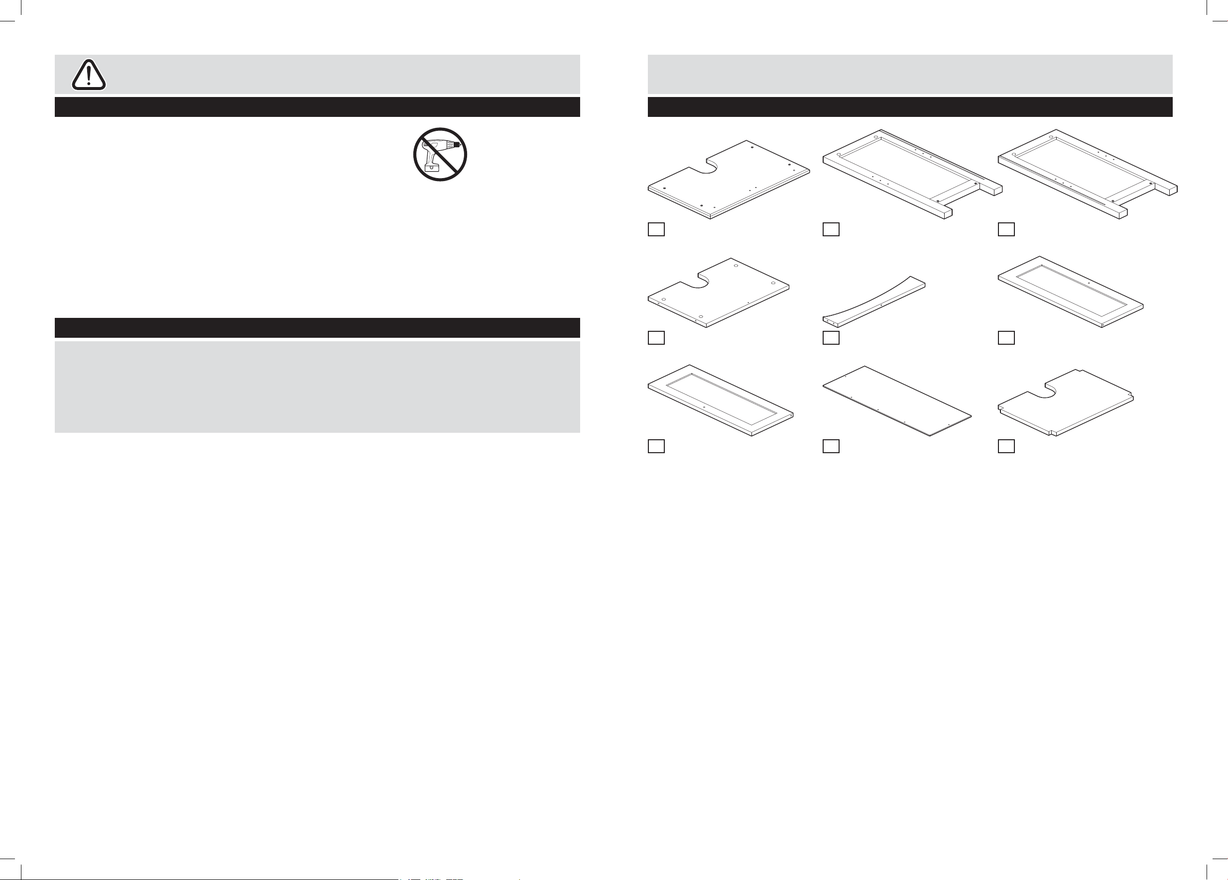
Please check you have all the panels listed below
Top x 1
1
(48(w)cm x 30(d)cm)
Base x 1
4
(40(w)cm x 28(d)cm)
Left side x 1
2
(58.5(h)cm x 28.5(d)cm)
Plinth x 1
5
(6(h)cm x 40(w)cm)
Right side x 1
3
(58.5(h)cm x 28.5(d)cm)
Left door x 1
6
(49.2(h)cm x 19.7(w)cm)
Right door x 1
7
(49.2(h)cm x 19.7(w)cm)
Back panel x 2
8
(52(h)cm x 9.5(w)cm)
Shelf x 1
9
(40(w)cm x 25.6(d)cm)
1
Page 3
Components - Fittings
If you have damaged or missing components,
call the Customer Helpline: 0845 640 0800
Assembly Instructions
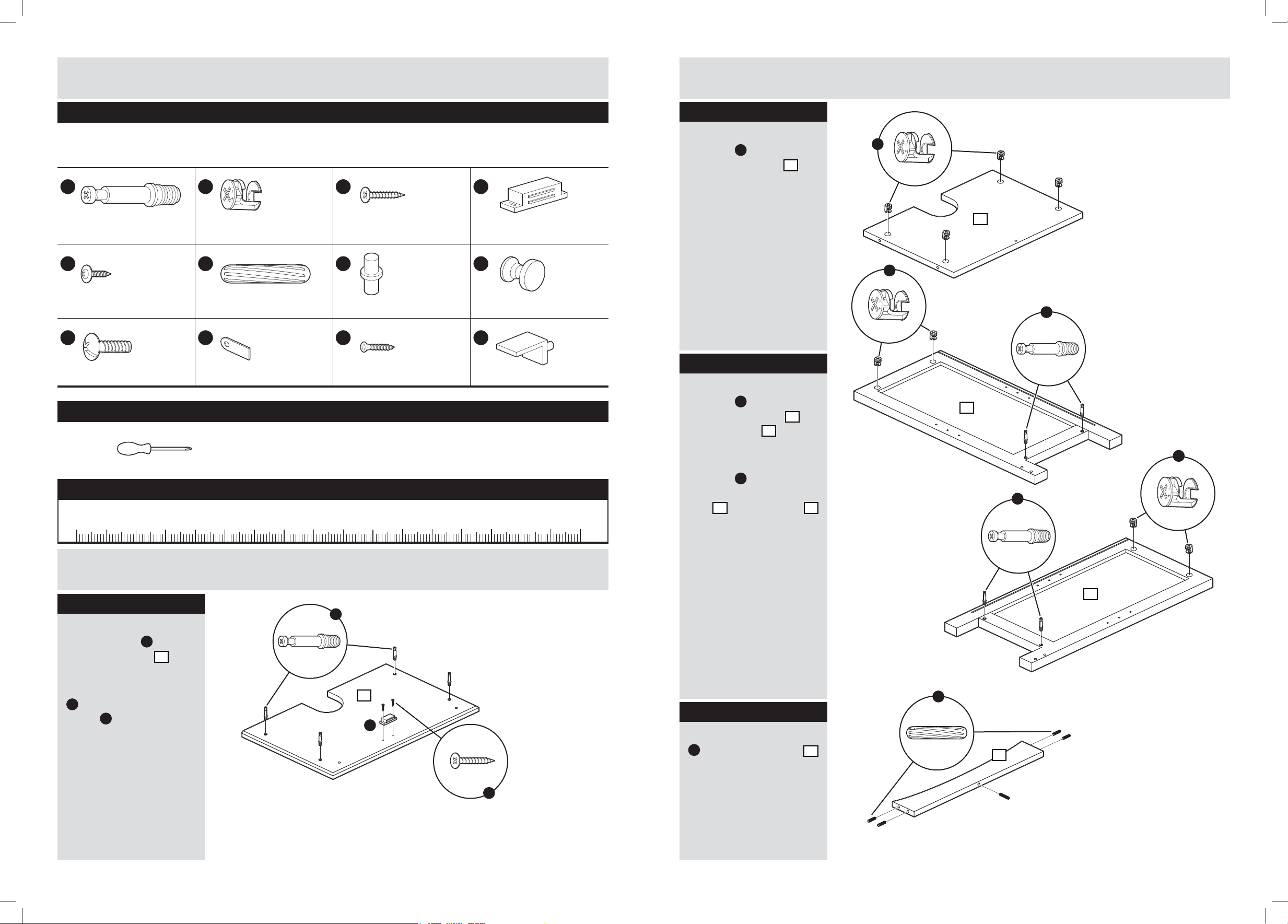
Please check you have all the ttings listed below
Note: The quantities below are the correct amount to complete the assembly. In some cases more ttings
may be supplied than are required.
A
35mm Male camlock x 8 Female camlock x 8 14mm Screw x 2 Magnetic catch x 1
E
Back panel screw x 10 Wooden dowel x 5 Hinge x 4 Knob x 2
I
16mm Screw x 2 Catch plate x 2 10mm Screw x 2 Shelf bracket x 4
B
F
J
C
G
K
D
H
L
Tools required
Phillips screwdriver
(medium & large)
Ruler – Use this ruler to help correctly identify the screws
105
0 5 10 15 20 25 30 35 40 45 50 55 60 65 70 75 80 85 90 95 100
110 115 120 125 130 135 140 145 150 155 160 165 170
Step 2
Insert 4 x female
camlock
underside of base
as shown.
B
into
4
Step 3
Screw 2 x 35mm male
camlock
bottom of left side
and right side
as shown.
Insert 2 x female
camlock
holes at the top of left
side
as shown.
A
into holes at
2
3
B
into the
2
and right side 3
B
4
B
A
2
B
A
Assembly Instructions
Step 1
Screw 4 x 35mm
male camlock
underside of top
as shown.
Connect magnetic catch
D
using 2 x 14mm
screw
C
.
A
into
1
3
A
1
F
Step 4
D
Insert 5 x wooden dowel
F
into the bottom rail 5
as shown.
C
5
2 3
Page 4
Assembly Instructions Assembly Instructions
Assembly Instructions Assembly Instructions
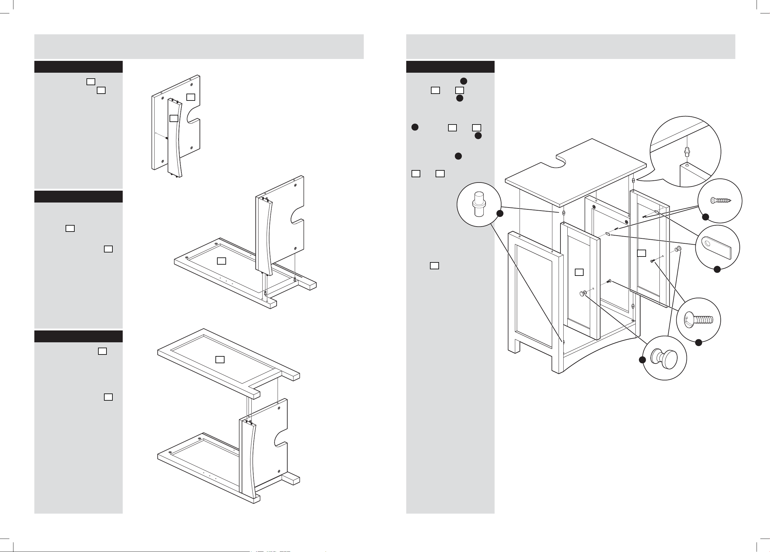
Step 3
Step 5
Screw 2 x male camlock
Connect plinth 5 to
A
underside of base
into reverse of drawer
13
front
as shown.
as shown.
4
Step 6
Connect assembly
completed in Step 5 to
left side
2
as shown.
Step 4
Tighten female camlocks
Connect hinges B to
in underside of base
top door
with a screwdriver.
door
Note: you should feel a
screws
click when the camlocks
are secured.
5
and bottom
6
using 15mm
F
as shown.
2
Step 6
Step 8
Connect top base 7
Connect knobs H to
and top shelf
doors
4
5
2
right side
16mm screws
shown.
Tighten female camlocks
in under side of top base
Connect catch plates
J
7
using 10mm screws
as shown.
Insert a hinge
top and bottom of doors
6
Note: it may be
helpful to have
assistance
from another
person with
the next stage.
Locate door hinges in
place in base as shown,
Connect top left side
then connect the top
to exposed ends of top
panel
base
top hinges of doors
9
slot into place (
Tighten female camlocks
tighten female camlocks
in under side of top base
on inside of left and right
7
side with a screwdriver.
6
with a screwdriver.
to doors 6 and 7
and
Step 7
1
7
and top shelf
as shown
with a screwdriver.
9
and 7 using
7
ensuring that
to top
I
2
.
as
G
into the
as shown.
K
a:), and
a:
G
1
6
7
K
J
Step 7
Connect right side 3 to
other end of assembly
completed in Step 5 as
shown.
Tighten female camlocks
in underside of base
with a screwdriver.
Note: you should feel a
Step 5
click when the camlocks
Insert 4 x 15mm female
are secured.
camlock
Note: it may be helpful
side of top base
to have assistance from
shown.
another person with this
Insert 4 x small wooden
stage.
dowel
9
as shown.
E
into under
D
into top shelf
2
7
as
Step 8
Screw 4 x male camlock
A
3
into the under side of
10
top
as shown.
H
I
Step 9
Connect top 10 as
shown.
Tighten female camlocks
with a screwdriver.
4 5
 Loading...