

Page 1
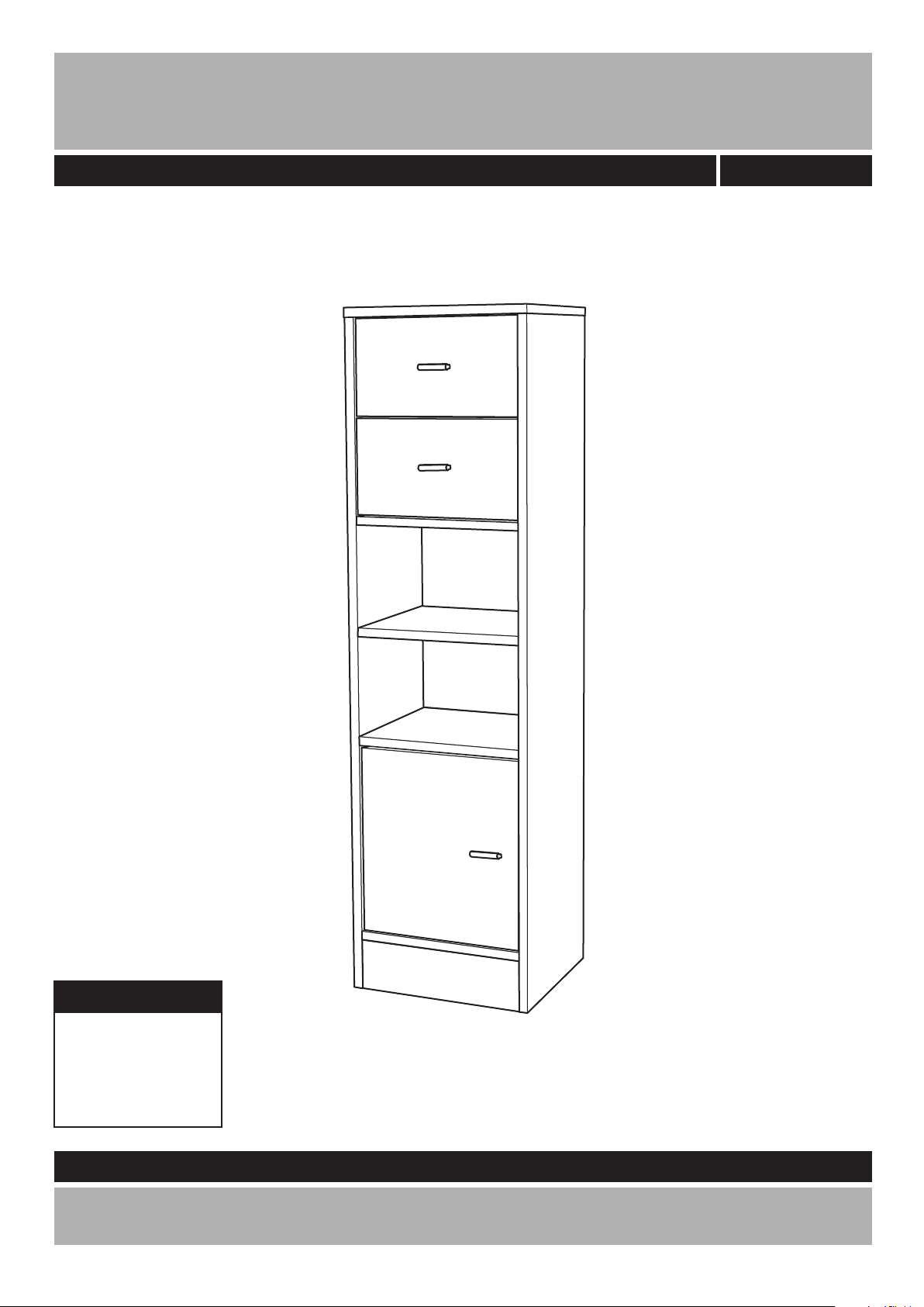
Medium Storage Unit
Assembly Instructions
-
Please keep for future reference
833/2471
Dimensions
Width - 32.5cm
Depth - 30.1cm
Height - 119.2cm
Important - Please read these instructions fully before starting assembly
If you need help or have damaged or missing parts, call the
Customer Helpline: 08456 400800
Version 2 Date: 26/09/11
Page 2
Safety and Care Advice
Important - Please read these instructions fully before starting assembly
• Check you have all the
components and tools listed on
pages 2 and 3.
• Remove all ttings from the
plastic bags and separate them
into their groups.
• Keep children and animals away
from the work area, small parts
could choke if swallowed.
• Make sure you have enough
space to layout the parts before
starting.
• Do not stand on the product,
this could cause damage.
• Assemble the item as close to
its nal position (in the same
room) as possible.
• Assemble on a soft level surface
to avoid damaging the unit or your
oor.
• Parts of the assembly will be
easier with 2 people.
as this could damage the unit.
Only use hand screwdrivers.
• Dispose of all packaging
carefully and responsibly.
• Note: Only apply the glue once
you are sure of the assembly.
Glue safety - Take care when using glue, please follow the advice below
Skin contact: Remove
contamination by washing with
soap and water. This procedure
should also be followed prior to
eating and drinking.
Eye contact: Rinse immediately
with clean water for 15 minutes
and seek medical advice.
If swallowed: Seek medical
advice immediately.
• We do not
recommend the
use of power
drill/drivers for
inserting screws,
Care and maintenance
• Only clean using a damp cloth
and mild detergent, do not use
bleach or abrasive cleaners.
• From time to time check that
there are no loose screws on
this unit.
• This product should not be
discarded with household waste.
Take to your local authority waste
disposal centre.
Note: if required the next
page can be cut out and used
as reference throughout the
assembly. Keep this page with
these instructions for future
reference.
1
Page 3
If you have damaged or missing components,
Components - Panels
call the Customer Helpline: 08456 400800
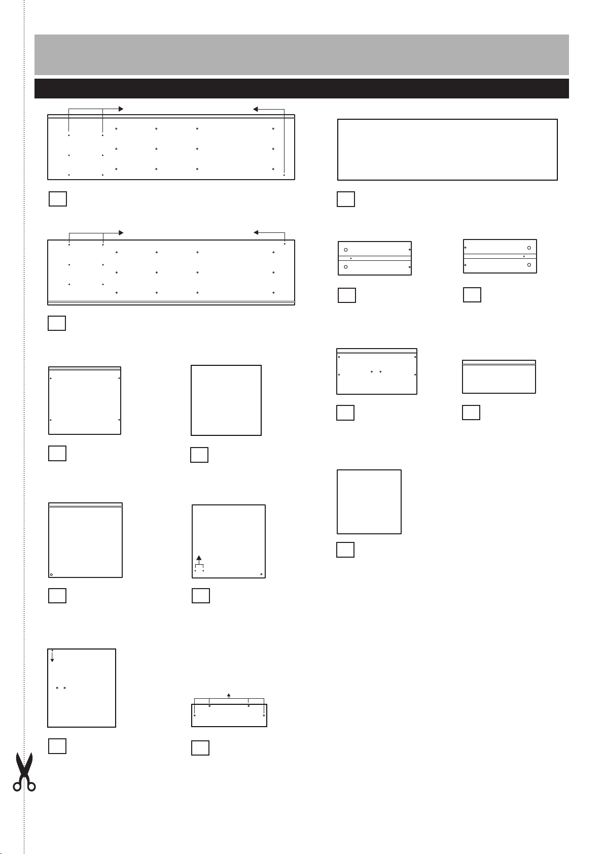
Please check you have all the panels listed below
Pilot holes for guidance only
Left side panel (117.6 x 29.9cm)
1
Pilot holes for guidance only
Right side panel
2
Top panel
3
(32.4 x 30cm)
(117.6 x 29.9cm)
Middle panel x 2
4
(29.3 x 28.4cm)
Back panel (107.9 x 30cm)
9
Drawer right
10
side panel x 2
(26.1 x 11.5cm)
Drawer front
12
panel x 2
(28.8 x 16.4cm)
Drawer left
11
side panel x 2
(26.1 x 11.5cm)
Drawer back
13
panel x 2
(26.1 x 11.5cm)
Bottom panel
5
(29.3 x 29.8cm)
Pilot holes for
guidance only
Door
7
(28.5 x 33cm)
Pilot holes
for guidance
only
Shelf
6
(29.3 x 28.4cm)
Pilot holes for guidance only
Front panel
8
(29.3 x 8.8cm)
Drawer bottom
14
panel x 2
(27 x 25.7cm)
2
Page 4
Components - Fittings
Note:
may be supplied than are required.
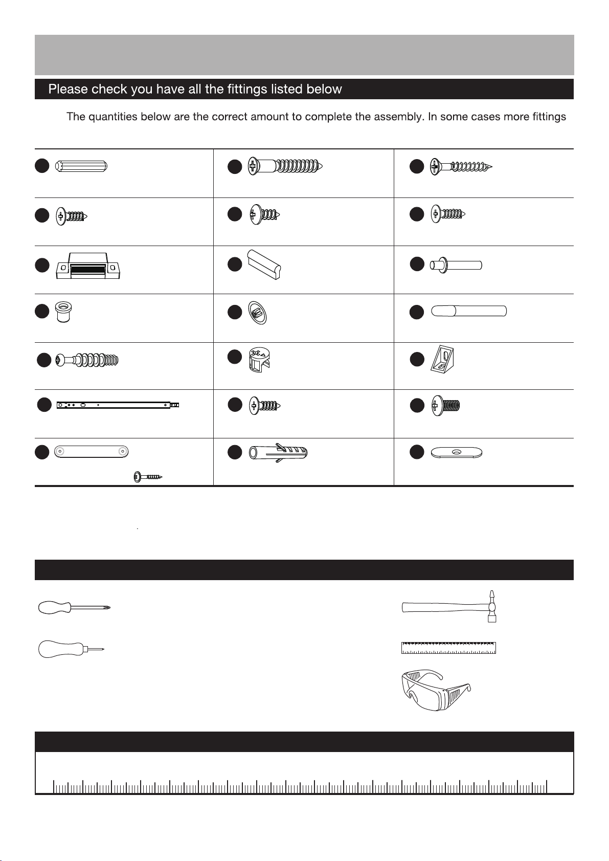
A
Wooden dowel x 16
D
12mm Screw x 1
G
Door stopper x 1
J
Hinge plug x 1
M
Locking pin x 8
P
Runner x 4
S
Wall strap x 1
(This screw is
included in the
wall strap bag)
x 1
B
50mm Screw x 12
E
14mm Screw x 9
H
Handle x 3
K
Screw cover x 12
N
Locking nut x 8
Q
(This screw is included in
the runner bag.)
12mm Screw x 12
T
Wall plug x 1
C
30mm Screw x 14
F
15mm Screw x 2
I
Door hinge
x 2
L
Glue x 1
O
Plastic support x 4
R
12mm Screw x 4
U
Metal plate x 1
Tools required
Phillips screwdriver
(medium & large)
Bradawl
(or sharp point)
Ruler - Use this ruler to help correctly identify the screws
105
0 5 10 15 20 25 30 35 40 45 50 55 60 65 70 75 80 85 90 95 100
110 115 120 125 130 135 140 145 150 155 160 165 170
0 1 2 3 4 5 6
110 120 130 140 1500 10 20 30 40 50 60 70 80 90 100
Eye protection
(when using a
hammer or glue)
Small
hammer
Ruler/tape
measure
3
Page 5
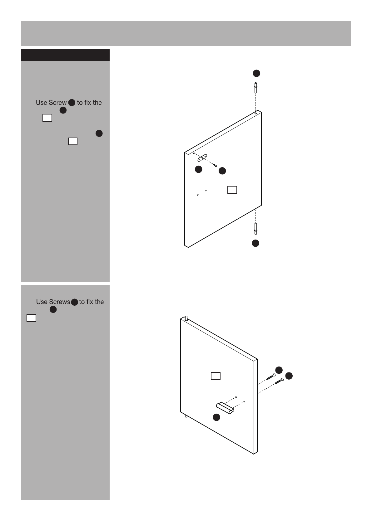
Assembly Instructions
Step 1
a:
F
itting hinges and
handle to door
I
a:
Metal plate onto the
Door .
7
D
U
Insert the Door hinges
into the Door .
7
I
U
D
7
I
b:
Handle onto the Door
7
H
.
C
b:
7
H
C
C
4
Page 6
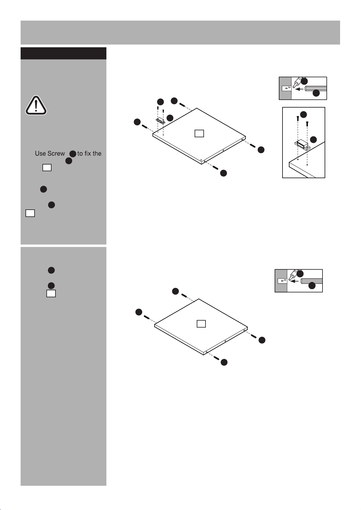
Assembly Instructions
Step 2
a:
Fitting dowels and
door stopper
Caution: Always
check the
assembly method
is correct before
applying glue.
a:
Door stopper onto the
Shelf .
6
s
F
G
Place a small amount of
L
Glue into the dowel
holes. Insert Wooden
dowels into the Shelf
6
A
.
A
F
L
A
A
G
6
A
A
F
G
b:
Place a small amount
of Glue into the dowel
L
holes. Insert Wooden
dowels into the Middle
panels .
A
4
b:
L
A
A
A
4
A
A
X 2
5
Page 7
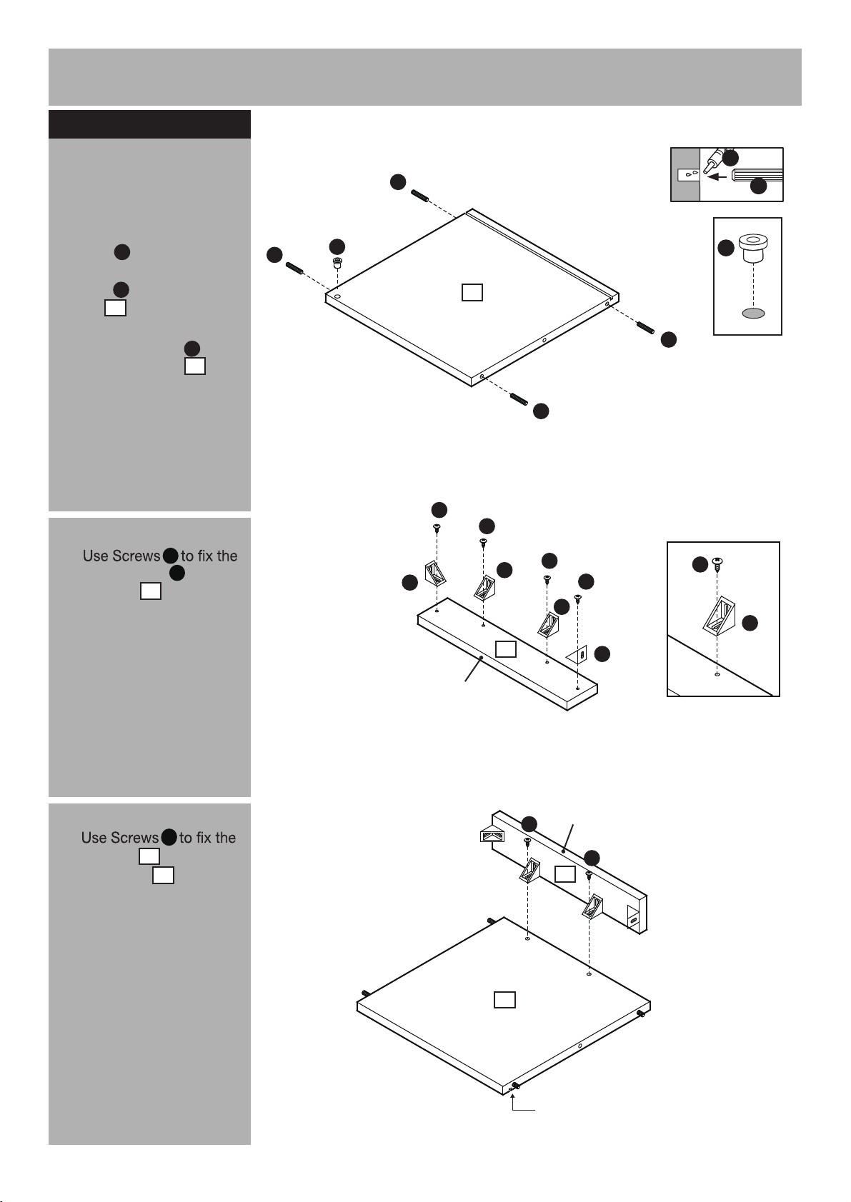
Assembly Instructions
Step 3
Fitting the bottom
panel
a:
Place a small amount
of Glue into the dowel
L
holes. Insert Wooden
dowels into the Bottom
panel .
Insert Hinge plug into
the Bottom panel .
b:
Plastic supports onto the
Front panel .
A
5
J
5
E
O
8
A
a:
b:
L
A
J
5
A
A
E
E
O
O
E
E
O
E
A
J
O
E
c:
Front panel onto the
Bottom panel .
E
8
5
c:
Finished
front edge
8
E
5
O
Finished
front edge
E
8
Groove underneath
6
Page 8
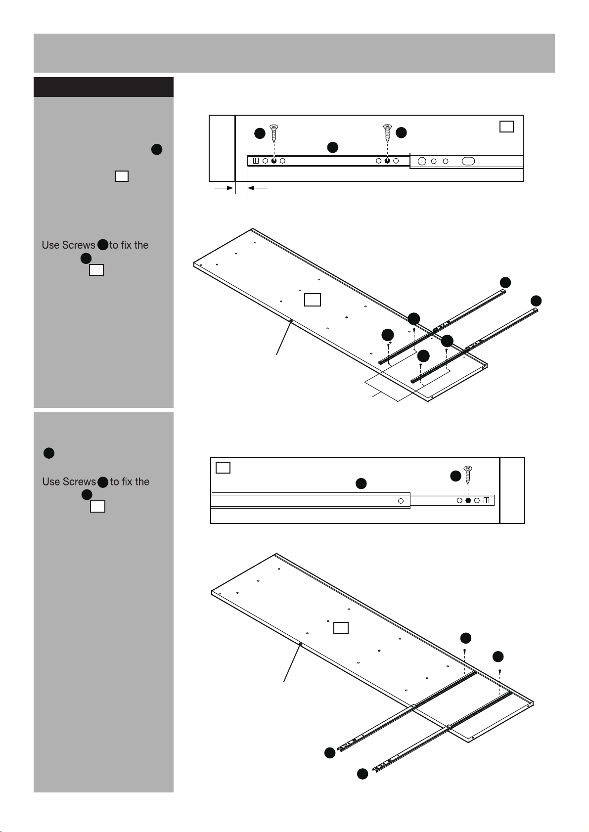
Assembly Instructions
Step 4
Attaching runners
a:
Position the Runners
in from front edge of the
Right side panel .
2
Slide top of the runners
back.
Q
Runners on the Right
side panel .
Note:
The front part of the
P
2
Runner should be
approximately 1.7cm from
the front edge of the panel.
P
a:
17mm
Middle hole
Q
Front edge
Q
P
2
Q
Q
Q
Q
2
P
P
b:
Slide top of the Runners
P
forward.
Q
Runners on the Right
side panel .
P
2
b:
Pilot holes for
runner position
2
P
2
F ront edge
Middle hole
Q
Q
Q
Continued on next page.
7
P
P
Page 9
Assembly Instructions
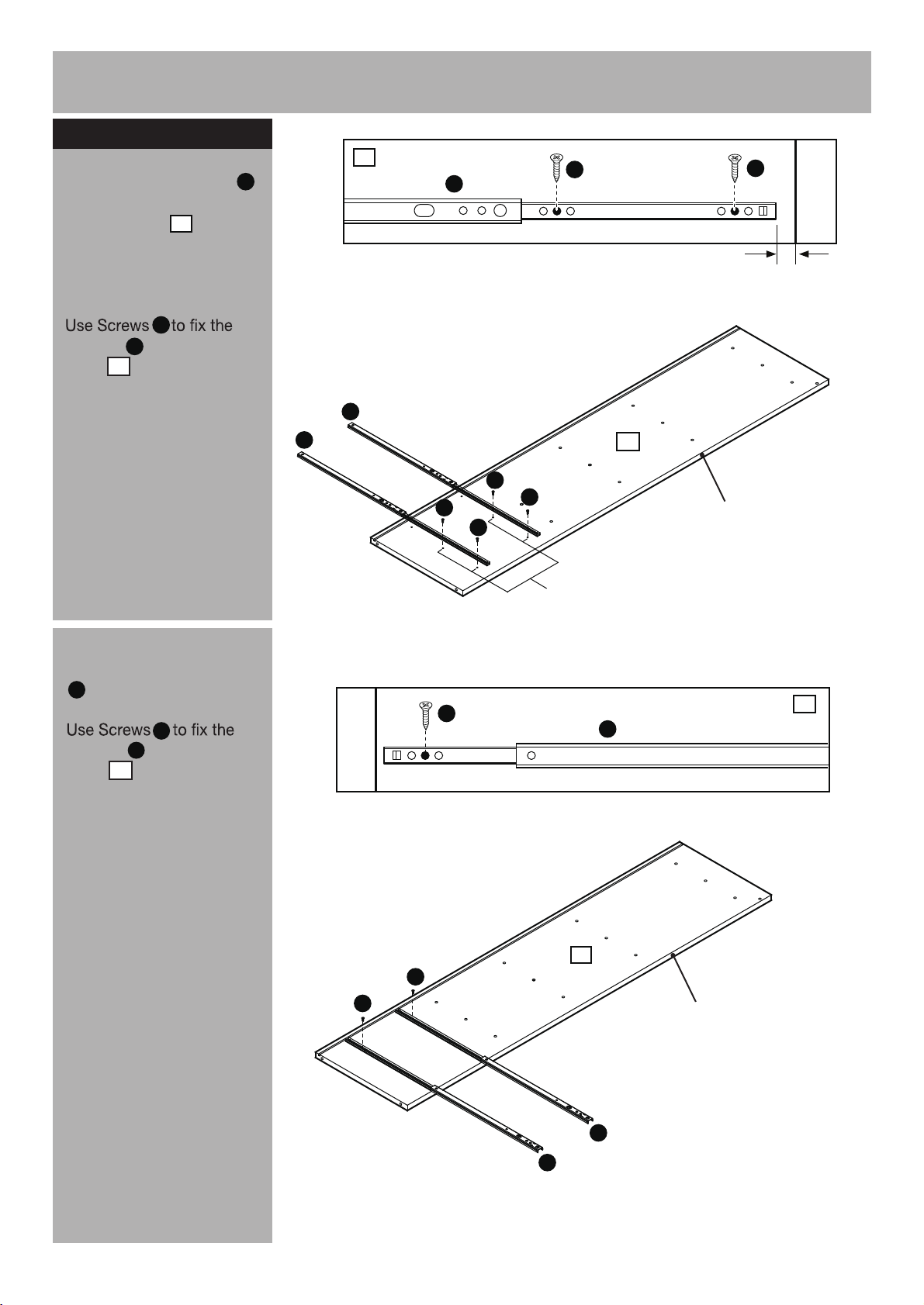
Step 4 - continued
1
c:
Position the Runners
in from front edge of the
Left side panel .
1
c:
P
P
Q
Middle hole
Q
Slide top of the runners
back.
Q
Runners on the Left side
panel .
Note:
The front part of the
P
1
Runner should be
approximately 1.7cm from
the front edge of the panel.
d:
Slide top of the Runners
P
forward.
Q
Runners on the Left side
panel .
P
1
P
d:
17mm
P
1
Q
Q
Q
Q
Middle hole
Q
Front edge
Pilot holes for
runner position
1
P
1
Q
Q
P
P
Front edge
8
Page 10
Assembly Instructions
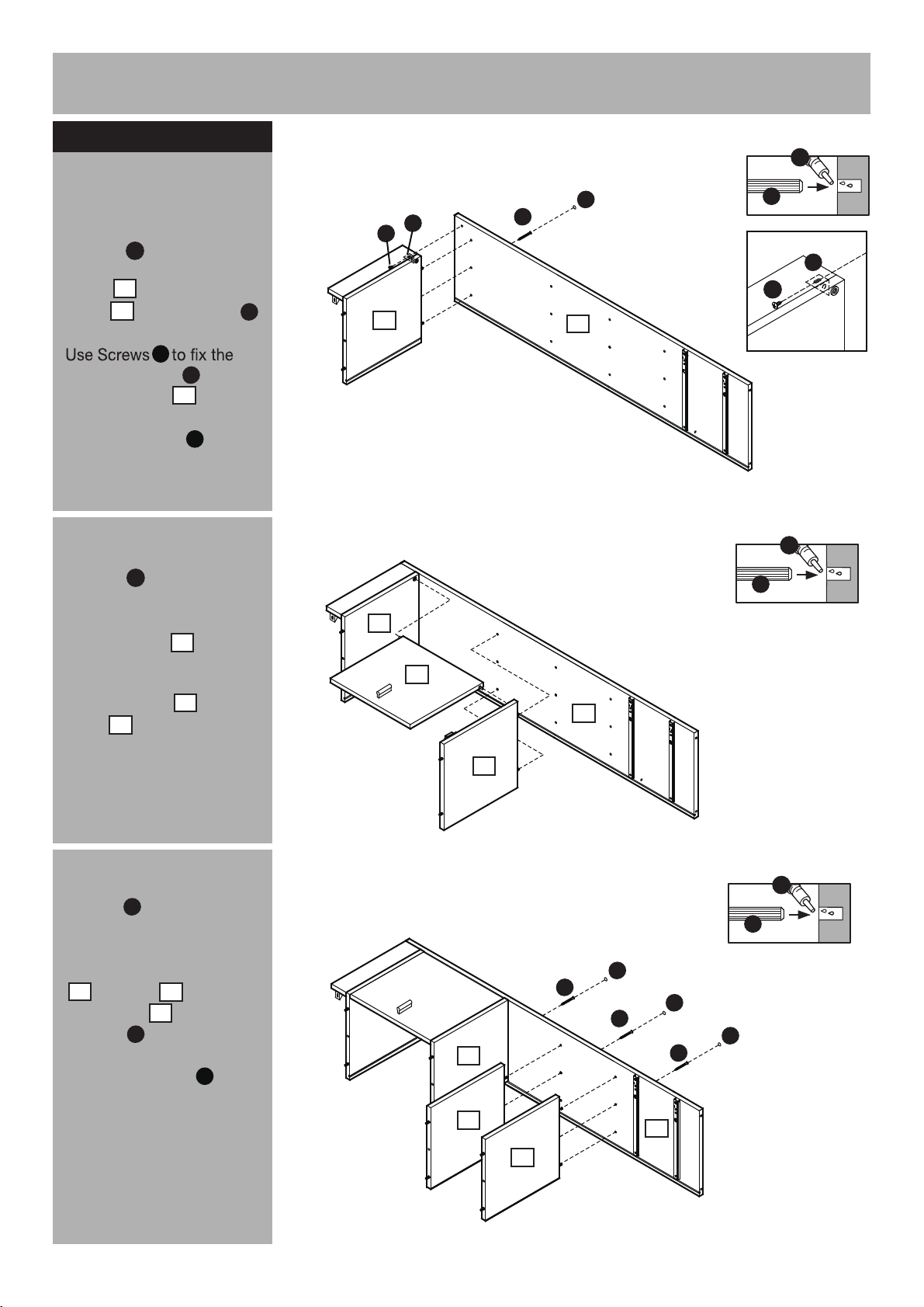
Step 5
a:
Fitting left side panel
a:
Place a small amount
of Glue into the dowel
holes. Position Bottom
panel onto Left side
panel using Screws .
Plastic supports onto the
Left side panel .
Use Screw cover to
cover the Screw heads.
b:
of Glue into the dowel
holes.
Position Door onto
the unit, locating the
hinges into plug on
Bottom panel and
Shelf and
corresponding holes.
L
5
1
E
O
1
K
Place a small amount
L
7
5
6
B
b:
L
K
O
E
5
5
7
B
1
1
6
A
O
E
L
A
c:
Place a small amount
of Glue into the dowel
L
holes.
Position Middle panels
4
& Shelf onto Left
side panel using
Screws .
Use Screw covers to
cover the Screw heads.
Continued on next page.
9
6
1
B
K
c:
L
A
K
B
B
6
4
4
K
K
B
1
Page 11
Assembly Instructions
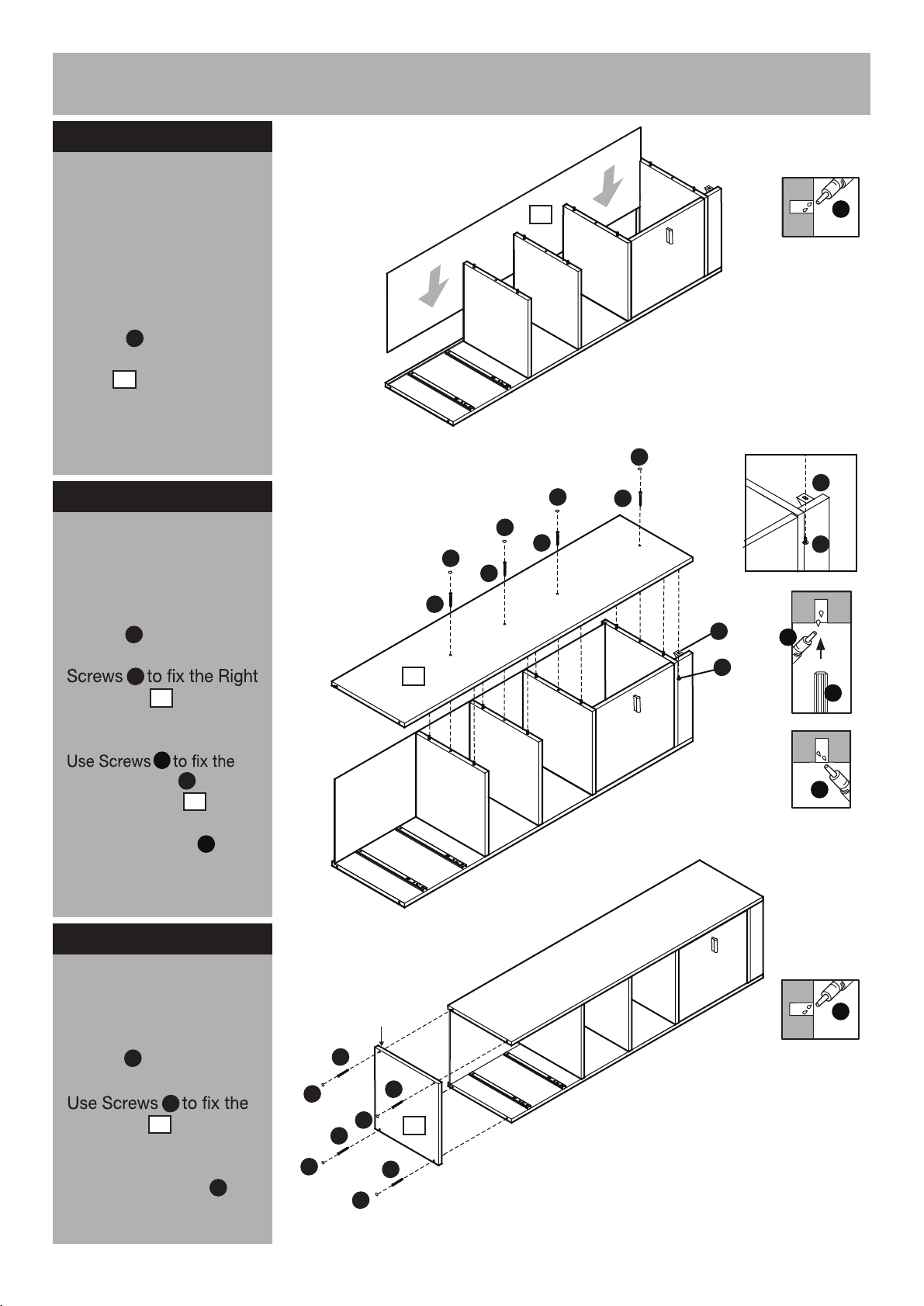
Step 6
Fitting the back panel
Note:
to ask someone to help
you at this stage.
Place a small amount
of Glue into the groove.
Carefully slide the Back
panel onto the unit.
Fitting the right side
panel
It would be useful
L
9
Step 6
Step 7
9
K
K
K
B
K
B
B
L
O
E
Place a small amount
of Glue into the dowel
L
holes and groove. Use
B
side panel onto the
2
unit.
Plactic Support onto the
Right side panel .
Use Screw covers to
cover the Screw heads.
E
O
2
K
Step 8
Fitting the top panel
Place a small amount
of Glue into the groove.
L
2
Groove underneath
B
B
O
E
L
A
L
L
B
Top panel onto the
3
unit.
Use Screw covers to
K
cover the screw heads.
K
B
K
B
K
K
3
B
10
Page 12
Assembly Instructions
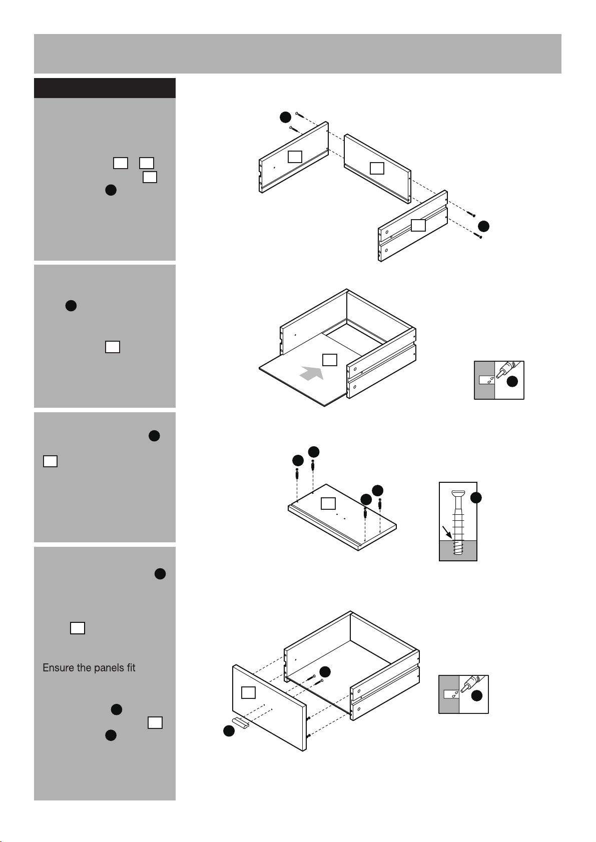
Step 9
a:
Drawer assembly
a:
Fix Drawer right and
left side panels &
to Drawer back panel
using Screws .
10
11
13
C
G
C
11
13
b:
Place a small amount of
L
Glue into the grooves.
Carefully slide the Drawer
bottom panel into the
unit.
Screw Locking pins
c:
into the Drawer front panel
.
12
Note:
Insert Locking pins
as far as shown.
Do not over tighten.
14
M
b:
c:
M
10
14
M
G
G
M
G
M
12
G
M
C
G
L
d:
Place a small of Glue
into the groove.
Position the Drawer front
panel onto the drawer
sides.
together without any gaps.
Fix the Handle onto
the Drawer front panel
using Screws .
Continued on next page.
11
12
H
C
12
L
d:
C
12
H
L
Page 13
Assembly Instructions
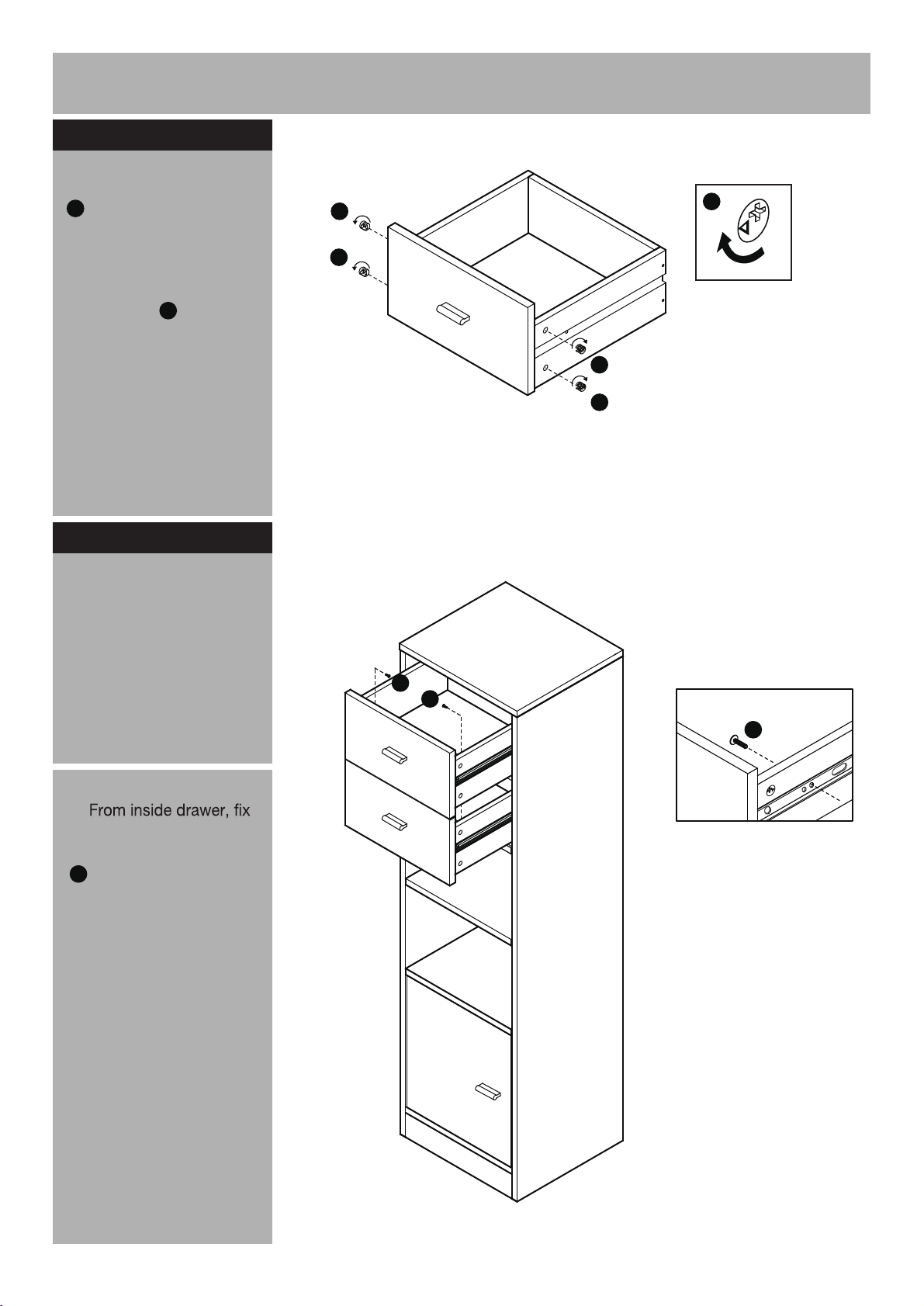
Step 9
e:
Insert 4 Locking nuts
N
into the holes in the
drawer sides(they will only
insert one way).
Use a screwdriver to turn
Locking nuts clockwise
to lock.
Repeat with remaining
drawer.
continued
-
N
Step 10
Inserting drawers
e:
a:
N
N
N
N
N
a:
Slide the assembled
drawers fully onto the
runners so the runners butt
up against the back of the
drawer front.
b:
through drawer sides into
the runners using Screws
R
.
R
R
b:
R
12
Page 14
Assembly Instructions
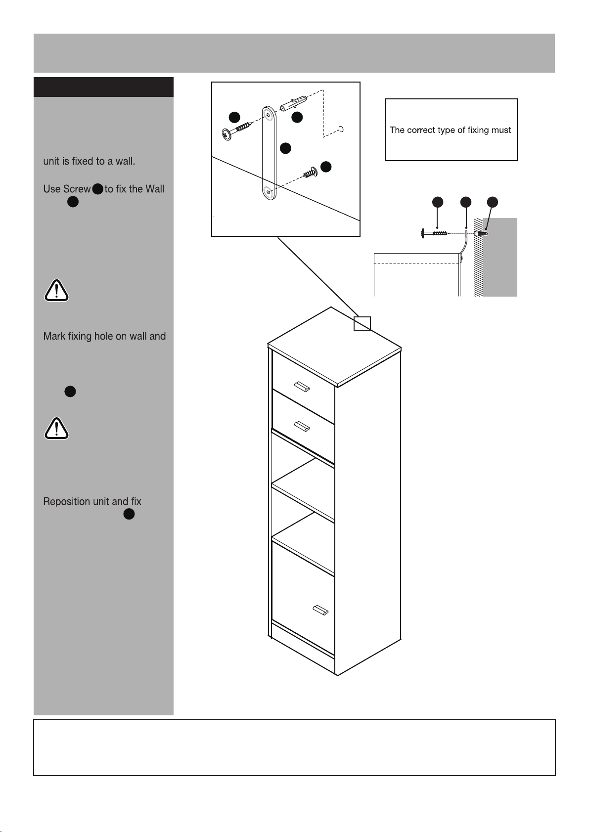
Step 11
Fixing to wall
S
Note:
T
wall
Wall plugs supplied are
for solid wall only.
It is recommended that the
E
S
strap onto the back of
top panel.
With help, move unit into
position.
Warning:
The unit is heavy.
Lift with care.
remove unit.
Drill a hole and insert Wall
T
plug .
Warning:
Before drilling,
check wall for
hidden pipes and
and cables.
S
Top panel
be used for your wall, seek
professional advice if in doubt
E
S
S
T
Wall
strap using Screw .
Note:
Glue to dry for 24 hours
and make sure the unit is
secure.
Before use allow the
S
Customer Helpline: 08456 400800If you need help or have damaged or missing parts, call the Customer Helpline: 08456 400800
13
Page 15
A Guide to - Wall Mounting & Fixings
Important note:
If plastic wall plugs
are supplied with your
product:
- these are only suitable for
use in masonry walls.
If you are in any doubt about
the correct wall plugs for
your wall, seek professional
advice.
Failure of the product due to
responsibility of the installer.
Important: When drilling into walls always
check that there are no hidden wires or pipes etc.
Make sure that the screws and wall plugs being used
are suitable for supporting your unit. Consult a qualified
tradesperson if you are unsure.
Hints:
1: General rule: Always use a larger screw and wall plug
if you are not sure.
2: Ensure you use the recommended drill bit to match the wall
plug and hole size.
3: Ensure you drill the hole horizontally, do not force the drill or
enlarge the hole.
4: Take extra care when drilling high walls, ceilings and ceramic
tiles. Ensure wall plugs are inserted beyond the thickness of
the ceramic tiles to avoid the tiles splitting or cracking.
5:
drilled hole.
Types of walls
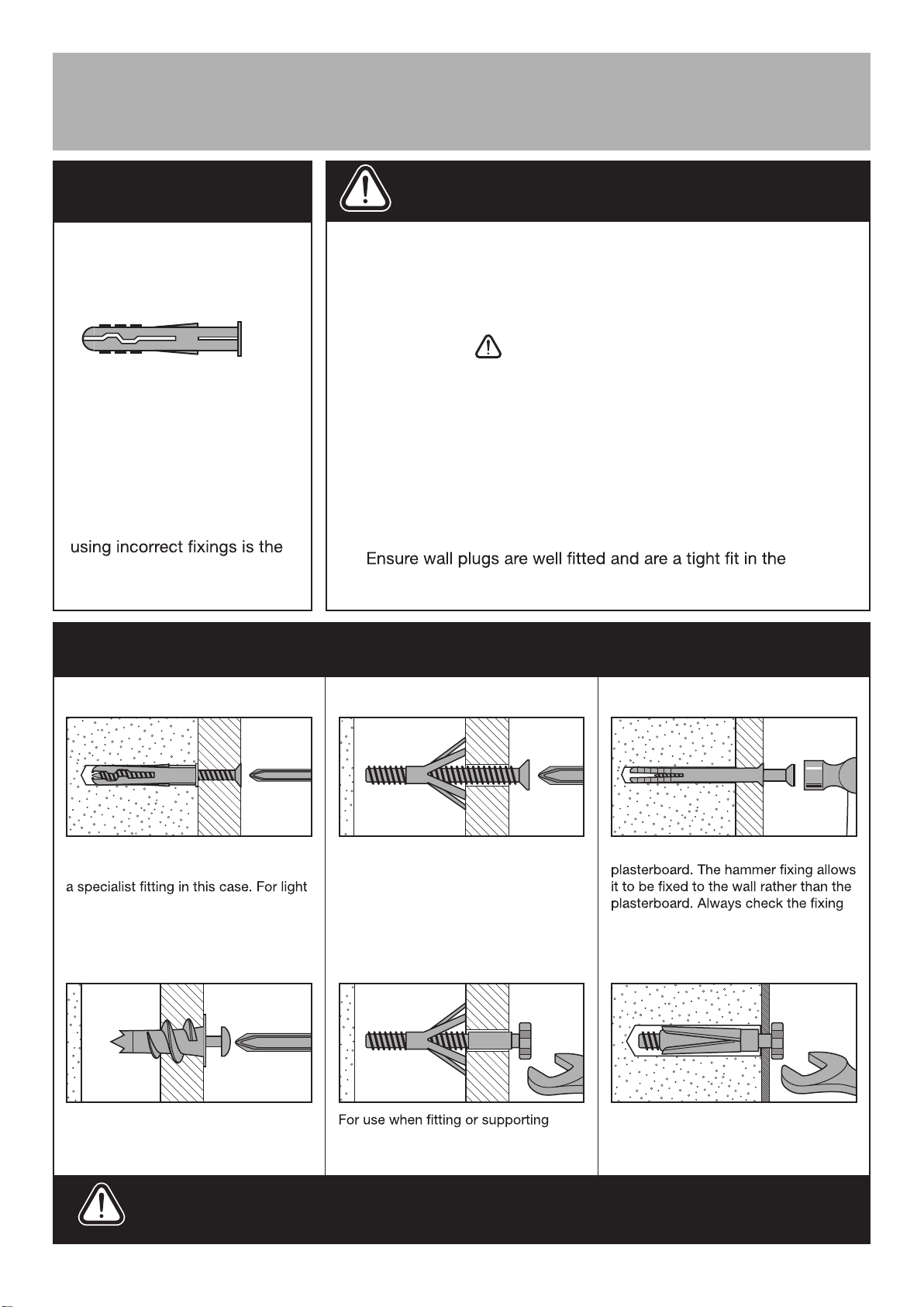
No.1 “General Purpose” wall plug
Generally aerated blocks should not
be used to support heavy loads, use
loads, general purpose wall plugs can
be used.
No.2 “Plasterboard” wall plug
You can use one of the following types of wall plug if your walls are made
of brick, breeze block, concrete, stone or wood.
No.3 “Cavity Fixing” wall plug
For use with plasterboard partitions or
hollow wooden doors.
No.4 “Cavity Fixing-Heavy Duty”
wall plug
No.5 “Hammer Fixing” wall plug
For use with walls stuck with
is secure to the retaining wall.
No.6 “Shield Anchor” wall plug
Heavy loads
For use when attaching light loads on
to plasterboard partitions.
Care &
Maintenance
heavy loads such as shelving, wall
cabinets and coat racks.
Safety: Always check the fitting
and location to ensure your safety
in and around the home.
For use with heavier loads such as TV
& HiFi speakers and satelite dishes etc.
Fitting: From time to time check
the fitting to ensure the wall plugs
or screws do not become loose.
Revision 2 - 7/10/09
 Loading...