

Page 1
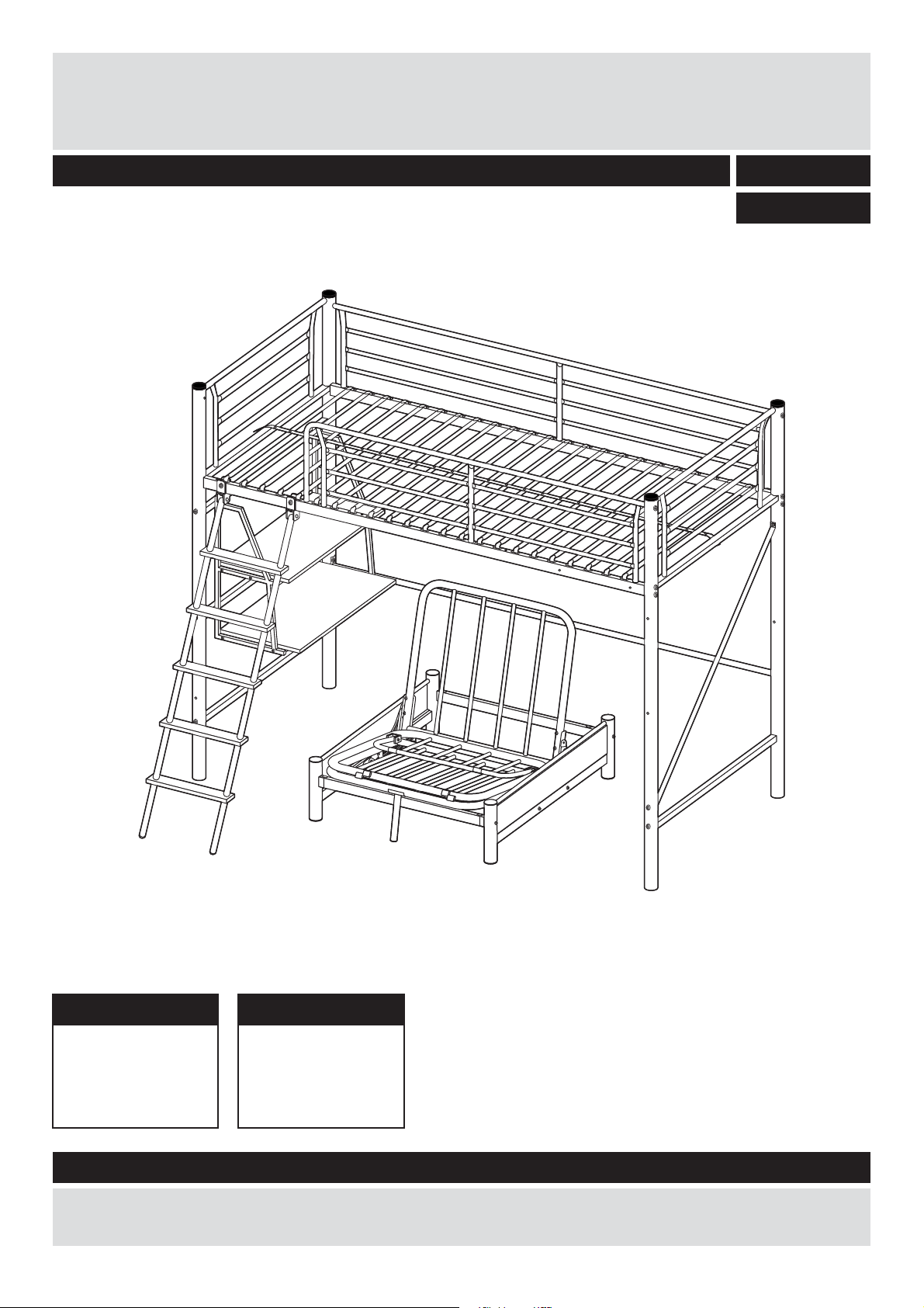
09 SITNSLEEP METAL HIGHSLEEPER FRAME
Assembly Instructions - Please keep for future reference
758/5401
758/5418
Bed unit dimensions
Width - 201cm
Depth - 154cm
Height - 179cm
Sofa unit dimensions
Width - 202cm
Depth - 85.5cm
Height - 25.5cm
Important - Please read these instruction fully before starting assembly
If you need help or have damaged or missing parts, call the Customer Helpline: 08456 400800
Issue 1 - 2/01/10
Page 2

Safety and Care Advice
IMPORTANT – READ CAREFULLY–RETAIN FOR FUTURE REFERENCE
Care and maintenance
and mild detergent, do not use
bleach or abrasive cleaners.
there are no loose screws on
this unit.
Keep These Instructions For Future Reference
This product complies with
EN 747-1:2007
Argos plc
489-499 Avebury Boulevard
Central Milton Keynes
MK9 2NW
discarded with household
waste. Take to your local
authority waste disposal centre.
if required the next
Note:
page can be cut out and used
as reference throughout the
assembly. Keep this page with
these instructions for future
reference.
1
Page 3
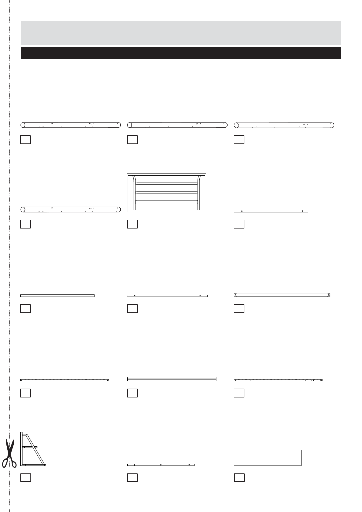
Components
Please check you have all the panels listed below
Metal leg
1
Metal legX1(179 x 4.8cm)
4
Base frame X 2(88.7x2cm) Base frameX1(129 x 3cm)
7
(179 x 4.8cm)X 1
Metal leg X 1(179 x 4.8cm)
2
HeadboardX2(89.9 x 39.4cm)
5
Filler barX2
8 9
(91x3cm)
Metal leg X 1(179 x 4.8cm)
3
Base frameX2(88.7 x 2cm)
6
Side rail (190.7x4cm)X 1
10
Desk frame X 2(57.3x30.8cm)
13 14
11
Side rail (191.3x1.9cm) liarediS1X (190.7x4cm)X 1
Base frame X 4(70.4 x 1.6cm)
12
Upper desk panelX1(70 x 28cm)
15
Argos
2
Page 4
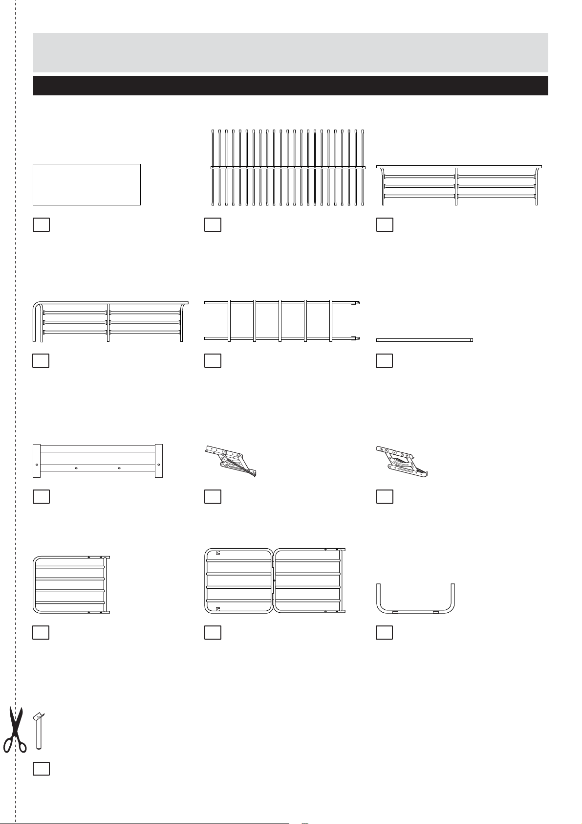
Components
Please check you have all the panels listed below
Lower desk panel X 1
16
Front safety barrierX1
19
(154x37cm)
Side frameX2(96.8x25cm)
22 23
(70x40cm)
17
20
Bed slatX1 (190.7x93.4cm)
LadderX1(152 x 37.5cm)
Spring hinge (46x16cm)X 1
Back safety barrierX1
18
(190.3x37cm)
Base frameX2(75.3 x 4cm)
21
Spring hinge (46x16cm)X 1
24
Sofa slat (71.5 x 64.5cm) talsafoS1X (130.9x71.5cm) leetstooF1X (64.6x23.5cm)X 1
25 26 27
28
3
Foot steel
(18.7 x 7cm)X 1
Page 5
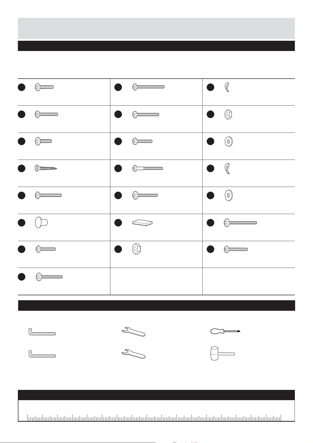
If you have damaged or missing components,
Components - Fittings
call the Customer Helpline: 08456 400800
Please check you have all the fittings listed below
Note: The quantities below are the correct amount to complete the assembly. In some cases more
fittings may be supplied than are required.
A
M6 x 20mm Boltsx8
D
M6 x 45mm Boltsx6
G
M6 x 18mm Boltsx4 M6 x 35mm Boltsx14
J
25mm Self-tapping screw x 8
M
M6 x 55mm Boltsx5
P
Plastic coverx22
B
M6 x 70mm Boltsx16 Ø 216 Washersx2
E
H
K
M8 x 75mm Boltsx3
N
M8 x 55mm Boltsx1
Q
Sticky padx4
C
F
M6 Nutsx4M6 x 61mm Boltsx2
I
Ø18 Washersx19
L
Ø19 Washersx3
O
Ø 0 20Washersx2
R
M8x70mm Boltsx4
S
M8 x 32mm Boltsx4
V
M8 x 45mm Boltsx1
T
M8 Nutsx12
Tools required
Allen key M4
(included)
Allen key M5
(included)
Spanner M6
(included)
Spanner M8
(included)
Ruler - Use this ruler to help correctly identify the screws
U
M8x38mm Boltsx10
Screwdriver
(not included)
Rubber mallet
(not included)
0 5 10 15 20 25 30 35 40 45 50 55 60 65 70 75 80 85 90 95 100 110 120105 115 125 130 135 140 145 150 155 160 165 170
4
Page 6
Assembly I nstructions
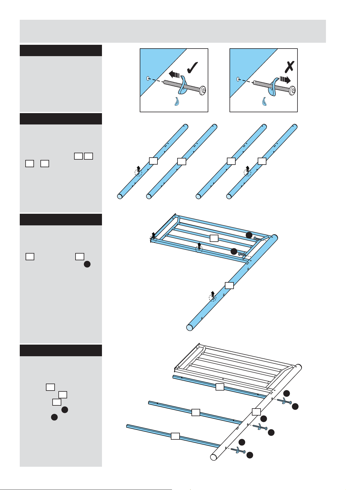
Step 1
Note : Pleas e ensure
theWASHER is curving
in facing the hole
befo r e assemblin g.
Step 2 - Bed unit
Preparing metal leg
Please be c areful to
select metal leg , ,
& for assmbling.
3 4
1 2
Step 3
Attaching headboard
Attach 1 pc of me tal leg
to headboard by
1 5
using 2 pcs of bolt s .
A
The washer curving in
facing the hole is correct.
1
2
The washer curving out
facing the hole is incorrect.
3
5
A
4
A
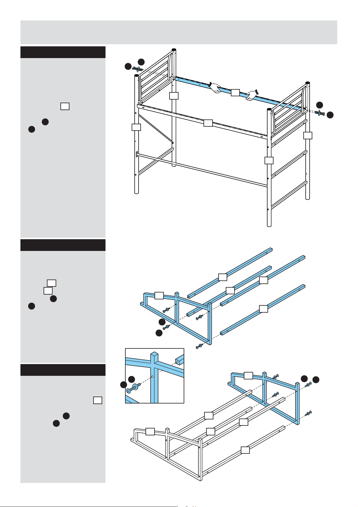
Step 4
Attaching base frame
Attach 2 pcs of base
frames and 1pc of
base fram e to the
metal leg by using 3
pcs of bolt s and
washers
6
7
1
B
.
C
1
6
C
6
7
1
C
B
C
B
B
5
Page 7
Assembly Instructions
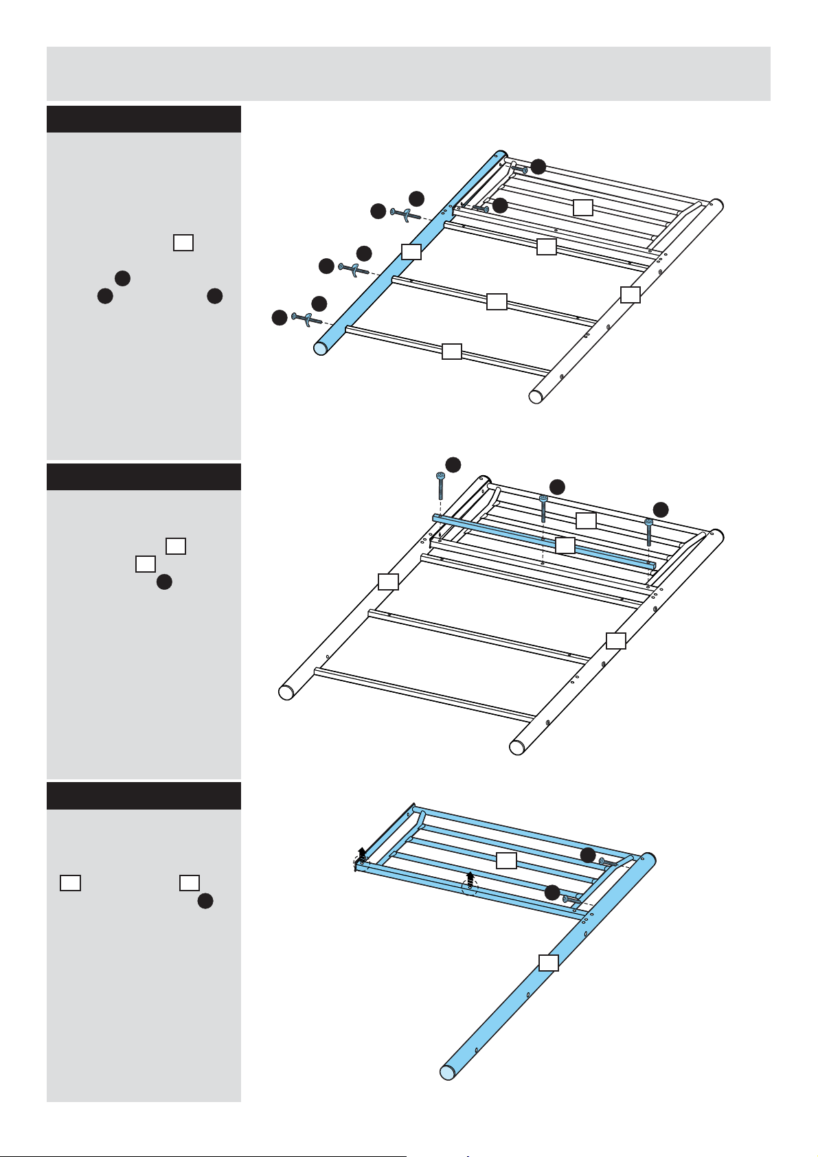
Step 5
Attaching metal leg
Two people are required
here.
Attach metal leg to
2
the unit b y using 2 pcs
of bolts and 3 pcs of
bolts and washers
A
B
C
Step 6
Attaching filler bar
Attach filler bar to
headboard by using
3 pcs of bolts .
8
5
D
A
C
B
C
B
.
C
B
2
7
D
2
A
6
5
6
1
D
D
5
8
Step 7
Attaching headboard
Attach 1 pc of metal leg
to headboard by
3 5
using 2 pcs of bolts .
A
1
5
A
A
3
6
Page 8
Assembly Instructions
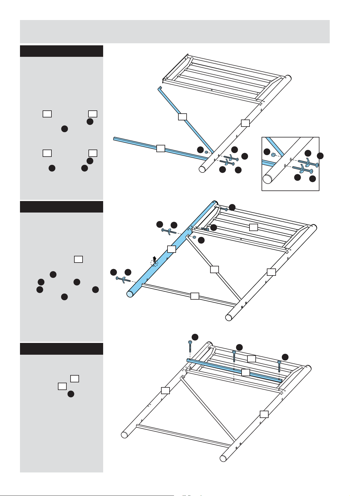
Step 8
Attaching base frame
Two people are required
here.
Attach 1 pc of base
a:
frame to metal leg
by using 1 pc of bolt
and washer .
b:
frame to metal leg
by using 1 pc of bolt ,
washer and nut .
7
C
Attach 1 pc of base
9
C F
3
B
3
E
Step 9
Attaching metal leg
Two people are required
here.
a:
b:
9
3
7
E
C
4
F
A
F
C
E
C
B
A
F
5
C
E
C
B
Attach metal leg to
4
the unit b y using 2 pcs
of bolts and 1pc of
bolt , washer and
nut and 1 pc of bolt
and washer from top
A
E
F B
C
C
to the end.
Step 10
Attaching filler bar
Attach filler bar to
headboard by using
3 pcs of bolts .
8
5
D
B
C
7
D
4
9
D
5
8
3
D
3
7
Page 9
Assembly Instructions
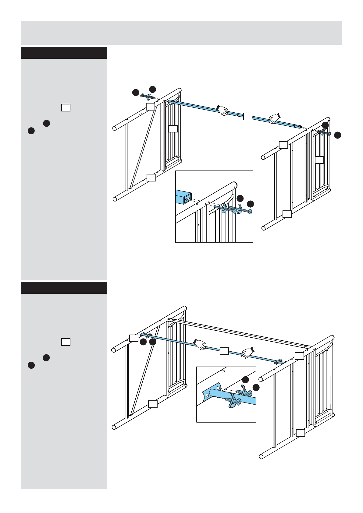
Step 11
Fitting side rail
Two people are required
here.
Fix side rail to the
10
unit by using4pcs of
bolts and washers
B
C
.
C
B
4
10
5
1
3
C
B
2
C
B
5
Step 12
Fitting side rail
Two people are required
here.
Fix side rail to the
unit by using4pcs of
bolts and washers
G
C
.
11
4
GC
11
1
C
G
3
2
8
Page 10
Assembly Instructions
Step 13
C
Fitting side rail
Two people are required
here.
Fix side rail to the
12
unit by using4pcs of
bolts and washers
B
C
.
B
4
3
10
12
C
B
2
1
Step 14
Attaching base frame
Attach 4 pcs of base
frames to the desk
frame by using4pcs
of bolts and washers
14
13
H
I
.
Step 15
Attaching desk frame
Attach the desk frame
to the unit by using 4
pcs of bolts and
washers .
H
I
13
14
13
I
H
I
H
14
13
14
14
14
13
14
14
I
H
14
9
Page 11
Assembly Instructions
Step 16
Fitting upper desk
panel
13
Fix the upper desk panel
to the unit by using 4
15
pcs of screws .
J
Step 17
Fitting lower desk
panel
Fix the lower desk panel
to the unit by using 4
16
pcs of screws .
J
13
J
15
J
14
16
J
13
J
14
J
Step 18
Attaching bookshelf
Two people are required
here.
Attach the bookshelf
unit to the bedframe by
using 4 pcs of bolts
and washers .
I
H
14
13
J
12
3
4
10
15
13
16
I
I
H
2
H
1
10
Page 12
Assembly Instructions
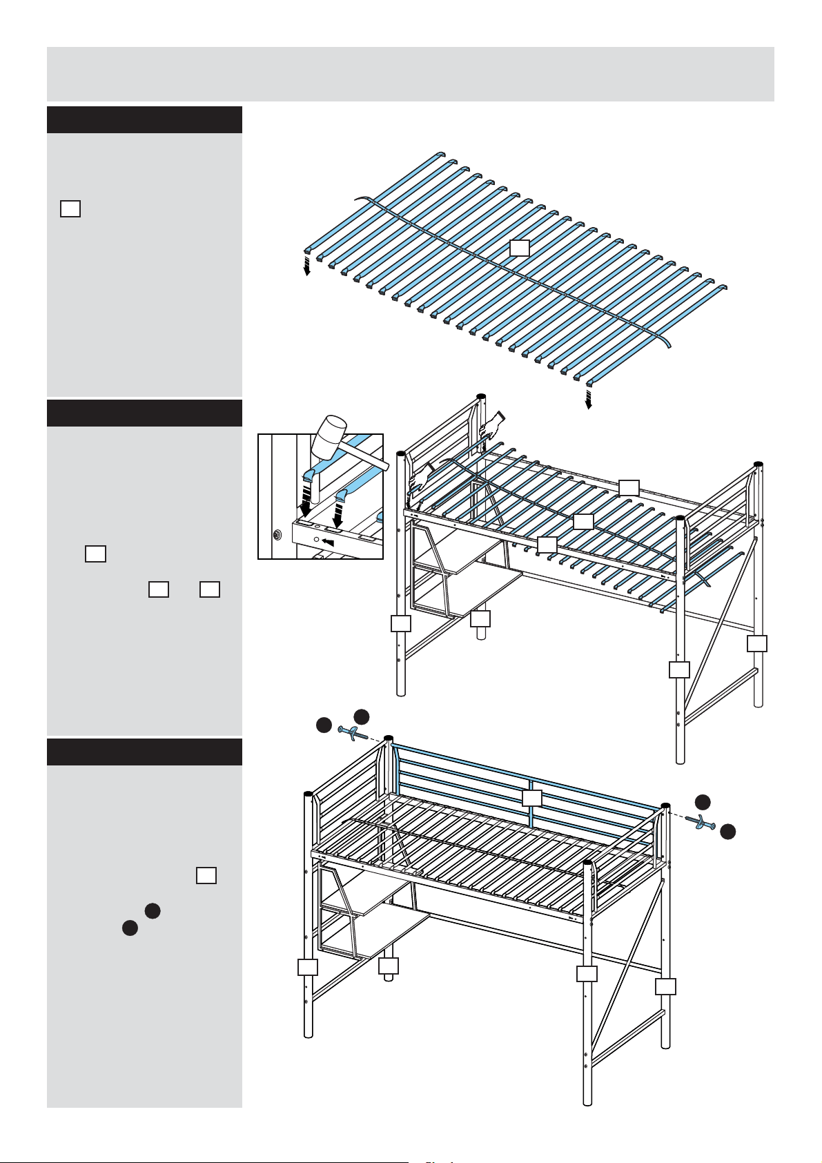
Step 19
Preparing bed slat
Spread out the bed slat
, each hook should
17
be pointed downwards
as shown.
Step 20
Attaching bed slat
17
Two people are required
here.
Insert each hook of bed
slat into the
17
corresponding holes of
the side rails and .
10 12
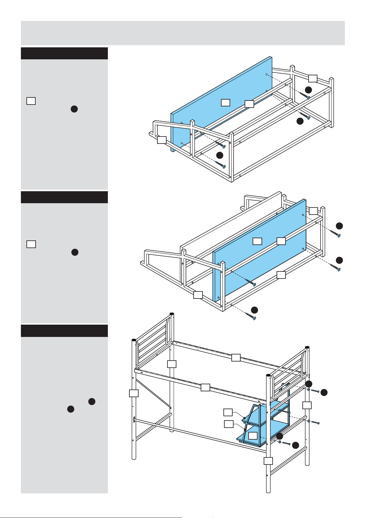
Step 21
Attaching side frame
Two people are required
here.
Attach back barrier
to the unit by using 2
pcs of b and
washers .
olts
L
K
18
10
17
12
2
L
K
1
4
3
18
L
K
11
2
1
3
4
Page 13

Assembly Instructions
Step 22
Fixing back safety
barrier
Fix back barrier to
18
the unit b y using 3 pcs
of bolts and washers
I
M
.
18
2
1
18
3
4
Step 23
Fixing front safety
barrier
Two people are required
here.
Fix front barrier to the
unit by using1pc of bolt
and washer and 2
K L
pcs of bolts and
washers and 1 pc of
bolt and washer
I
N O
from right side to left
side.
19
M
M
19
I
I
M
3
L
K
4
O
N
2
1
O
N
I
M
12
Page 14

Assembly Instructions
Step 24
Inserting plastic
cover
P
Insert 22 pcs of plastic
covers into unit by
hand.
P
2
P
P
10
12
4
P
P
1
3
P
P
Step 25
Attaching ladder
Two people are required
here.
Attach ladder to
a:
the side rail
Attach ladder to
b:
the unit b y using 2 pcs
of bolts , washers
and nuts .
H
F
12
20
.
20
I
a:
2
1
20
12
3
4
b:
F
I
H
13
20
Page 15

Assembly Instructions
Step 26
Assembly is complete
for the bed unit.
There are two option to
choose for assembling
the ladder and
bookshelf.
Warning:
Top of the
mattress shall
not come above
the line marked
on the bed.
OPTION 1
MAX:200mm
M
a
x
.
t
h
e
h
i
g
o
f
m
a
t
t
s
r
e
s
OPTION 2
MAX:200mm
M
a
x
.
t
h
e
h
i
g
o
f
m
a
t
t
s
r
e
s
14
Page 16

Assembly Instructions
Step 27 - Sofa unit
Attaching sticky pad
Q
Attach the sticky pad
onto both end of base
frames against the
21
friction between metal
frame.
Q
Q
Q
21 21
Q
Q
Step 28
Attaching base frame
Two people are required
here.
Fix the base frames
to the side frames by
using4pcs of bolts
and washers .
O
21
22
R
Step 29
Attaching spring
hinge
R
O
R
22
21
21
O
R
22
O
R
S
O
O
O
S
Two people are required
here.
Attach the spring hinge
to the unit by using 2
23
pcs of bolts , washers
and nuts .
O
S
T
15
21
22
23
T
T
22
21
Page 17

Assembly Instructions
Step 30
Attaching spring
hinge
Two people are required
here.
Attach the spring hinge
to the unit by using 2
24
pcs of bolts , washers
and nuts .
O
S
T
Step 31
Attaching sofa slat
21
22
22
21
24
T
O
S
U
O
Attach the sofa slat
25
onto the spring hinge on
the unit b y using 4 pcs
of bolts , washers
and nuts .
U
T
O
Step 32
Attaching foot steel
Fix the foot steel to
the sofa slat by using
2 pcs of bolts and
washers .
O
27
26
U
27
22
21
25
T
21
O
U
U
O
26
16
Page 18

Assembly Instructions
Step 33
Attaching foot steel
Two people are required
here.
Fix the foot steel to
28
the unit b y using 1 pc of
bolt and washer .
V
O
Step 34
Attaching sofa slat
V
26
O
28
U
O
Two people are required
here.
Attach the sofa slat
26
onto the spring hinge on
the unit b y using 4 pcs
of bolts , washers
and nuts .
T
OU
26
T
U
O
26
T
25
22
17
Page 19

Assembly Instructions
Step 35
Adjusting sofa seat
a: Fold sofa slat as
shown.
b: Lift sofa slat as
shown.
26
26
a:
26
25
22
b:
26
25
22
c: Lift sofa slat as
shown.
25
d: Move simultaneously
sections and to
adjust the sofa seat.
25 26
c:
26
25
21
22
d:
25
26
21
22
18
Page 20

Assembly Instructions
Step 36
Assembly is complete
for the sofa seat unit.
Step 37
Assembly is complete.
If you need help or have damaged or missing parts, call the Customer Helpline:
19
08456 400800
Page 21

Sit N’ Sleep Bed
Assembly Instructions - Please keep for future reference
7585418
7585401
IMPORTANT NOTE:
The top surface of the
mattress should not come
above this line.
Dimensions
Width - 200cm
Depth - 99/143cm
Height - 170.5cm
Important
If you need help or have damaged or missing parts, call the Customer Helpline: 08456 400800
- Please read these instructions fully before starting assembly
Issue 1 - 21/08/12
Page 22

Safety and Care Advice
Important - Please read these instructions fully before starting assembly
• Because of the size of this unit,
it is recommended to assemble it
in the room intended for use.
• Do not discard any of the
packaging until you have
checked that you have all the
parts and the pack of fittings.
• Discard all extra fittings and
keep fittings out of reach of
children.
Warnings
• READ CAREFULLY - RETAIN
FOR FUTURE REFERENCE
• Regularly check and ensure
that all bolts and fittings are
tightened properly.
• Always use the ladder for
entering and leaving the upper
bunk.
• The recommended mattress
size is L1900 x W910 mm.
• Ensure thickness of mattress
does not exceed 220 mm.
• Refrain from using the bunk
bed if any structural part is
broken or missing.
• Assemble this product on a flat
surface.
• Assemble all parts loosely
before tightening any bolts.
• At least 2 people are required
to assemble this product.
• Unit weight: 38.6kgs.
• Retain Assembly Instructions
for future reference.
• Please advise your children to
only enter and leave the upper
bunk by using the ladder.
• Please prohibit more that one
person on the upper bunk.
• Please prohibit children from
jumping on the upper and lower
beds.
• WARNING: Do not allow
children under 6 years of age to
use the upper bunk due to risk
of injury and falls.
• STRANGULATION HAZARD -
Never attach or hang items such
as ropes, strings, cords,
• We do not
recommend the
use of power
drill/drivers for
inserting screws,
as this could damage the unit.
Only use hand screwdrivers.
• Dispose of all packaging
carefully and responsibly.
harnesses and belts to any part
of the bunk bed.
• WARNING: Children can
become trapped between the
bed and the wall. To avoid risk
of serious injury the distance
between the top safety barrier
and the wall shall not exceed 75
mm or shall be more than 230
mm.
• THIS BED COMPLIES WITH
EN747-1:2012 / EN747-2:2012
Care and maintenance
• Please clean the unit surface
using either damp (not wet)
cloth and a mild domestic soap
solution or by using an
appropriate polish.
1
• Do not use any abrasive
materials when cleaning.
• From time to time check that
there are no loose bolts on this
unit.
Note: if required the next
page can be cut out and used
as reference throughout the
assembly. Keep this page with
these instructions for future
reference.
Page 23

Components - Parts
Please check you have all the parts listed below
Sticker “4”Sticker “3”Sticker “2”Sticker “1”
1 Back right-hand
Front right-hand
endpost
(Ø5 x 170.5cm)
5
Upper side safety rail x 2
(91 x 36 x 4cm)
Lower rail
8
(190 x 6.5 x 2.5cm)
2
end post
(Ø5 x 170.5cm)
6
Lower side rail x 2
(91 x 4 x 2cm)
3
end post
(Ø5 x 170.5cm)
7
9
Upper back safety rail
(190 x 41.5 x 2.5cm)
4Back left-hand
Front left-hand
end post
(Ø5 x 170.5cm)
Middle side rail x 2
(89 x 2 x 2cm)
10
Upper front safety rail
(190 x 41.5 x 2.5cm)
Slats (with webbing attached) x 24
11
(94 x 2.5 x 2.6cm)
2
Page 24

Components - Parts (cont.)
Please check you have all the parts listed below
Sticker “12” Sticker “13”
Left ladder side rail
12 Right ladder side rail
(Ø2.5 x 141cm)
15 Shelf side frame x 2
Ladder brace
(45.5 x 1.5 x Ø1cm)
13 Ladder step x 4
(Ø2.5 x 141cm)
16 Shelf brace x 4
(52 x 33 x 1.6cm)
14
(Ø2.5 x 29 cm)
17
(Ø1.3 x 72cm)
Small shelf panel
18 Big shelf panel
(72 x 24 x 1.2cm)
19 Back brace x 2
(72 x 33 x 1.2cm)
3
20
(135.5 x 2 x Ø1.3cm)
Page 25

If you have damaged or missing components,
Components - Fittings
call the Customer Helpline: 08456 400800
Please check you have all the fittings listed below
Note: The quantities below are the correct amount to complete the assembly. In some cases more fittings
may be supplied than are required.
A
M6 x 80mm Bolt x 11
D
M6 x 27mm Bolt x 12
G
Big screw x 8
J
M6 Curved washer x 19
M
M8 Lock nut x 6
P
B
M6 x 50mm Bolt x 8
E
M6 x 20mm Bolt x 11
H
Small screw x 2
K
Plastic washer x 8
N
Spring washer x 8
Q
C
M6 x 35mm Bolt x 2
F
M8 x 60 mm Bolt x 12
I
M8 Curved washer x 12
L
Wall strap x 1
O
Plastic cap x 8
Spanner x 1
Allen key x 1
Tools required
Crosshead screwdriver
Ruler - Use this ruler to help correctly identify the screws
0 15 30 45 60 75 905 20 35 50 65 80 9510 25 40 55 70 85 100 120 140105 125 145110 130 150115 135 155 160 165 170
4
Page 26

Assembly Instructions
Step 1
Assembling end panels
Lay all parts flat on a soft
surface on the floor to
avoid damaging any of
the parts.
Note:
Identify and
correctly position
end posts , ,
3 4
and by
1 2
looking for the
sticker label
pasted on the
posts.
Note:
Determine your
preferred shelf
position. Then
attach the middle
side rails
7
either on the left
or right.
a: b:
A J
Sticker “2” Sticker “1”
2
A J
6
2
RIGHT-HAND END PANEL
E
E
5
6
E
E
E
2
5
1
AJ
a: Attach the lower side
rail to end posts
2
and then secure
using washers and
A
bolts .
Note: Do not fully
tighten bolts at
this stage.
16
J
b: Attach the upper side
safety rail into position
and secure using bolts .
Repeat above steps to
assemble the left-hand
end panel as shown in
the diagram.
5
E
Note: Fully
tighten all bolts
using allen key .
Q
LEFT-HAND END PANEL
Sticker “4”
A J AJ
A J AJ
A J AJ
E
E
5
7
7
6
E
E
Sticker “3”
34
5
Page 27

Assembly Instructions
Step 2
Attaching rails
Note: Determine
your preferred
bunk bed entry
position. Then
attach the front
safety rail with
10
the entry space
positioned either
on the left or right.
a: Identify the correct
rails for assembly and
with the help of an
assistant attach the lower
tubes of upper back
safety rail , upper front
safety rail and lower
8
rail to end posts using
bolts , washers and
nuts .
9
10
F
M
I
Note:
Do not fix bolts on
lower holes of
back safety rail
at this stage.
Locate hole on
centre of lower
8
rail and make
sure to position it
up.
9
4
I
F
I
F
J
A
I
F
I
F
I
F
3
4
I
F
M
I
F
b:
J
10
M
M
8
A
3
9
10
hole up
c:a:
9
O
A
J
F
I
O
O
2
O
M
O
F
I
F
I
1
O
A
J
F
I
F
I
M
O
O
1
O
O
Do not fully
tighten bolts at
this stage.
b: Attach the top tubes
of upper back safety rail
9
and upper front safety
10
rail to end posts using
bolts and washers .
Note: Do not fully
tighten bolts at
this stage.
c: Insert plastic caps
into holes on the right
end posts & and fix
by pushing firmly as
shown.
1 2
JA
O
Option for
right upper bunk entry
3
4
right shelf position
Option for
left upper bunk entry
10 10
Option for
2
1
3
4
left shelf position
2
1
Option for
6
Page 28

Assembly Instructions
Step 3
Attaching back braces
a: Position the back
braces as shown and
attach it to upper back
safety rail using bolts
F
, washers and nuts .
b: Attach the back
braces to lower rail
using bolt as shown.
20
9
I
20 8
E
Note: After all
bolts in step 2
and 3 are
positioned, fully
tighten all bolts
and nuts using
allen key and
spanner .
Q
P
M
I
F
M
3
20
9
20
E
8
M
F
I
2
Step 4
Assembling shelf
a: Attach the shelf
braces to shelf side
frames using bolts
as shown.
b: Position the shelf
panels and as
shown and attach it to
shelf braces using
screws . Tighten screws
using a crosshead
screwdriver.
17
16
D
Note: Do not fully
tighten bolts at
this stage.
18 19
17
G
a: b:
9
M
20
3
F
I
20
E
20
8
a:
16
D
D
D
17
D
17
16
17
D
17
D
D
D
b:
17
16
D
18
Note: After all
bolts and screws
are positioned,
fully tighten all
G
18
G
17
G
17
G
G
17
bolts using allen
Q
key .
G
17
G
G
19
17
G
7
Page 29

Assembly Instructions
Step 5
Attaching shelf
Position the shelf on the
bed as shown and attach
the side frames to
middle right side rails
using bolts . Tighten
bolts using allen key .
16
7
D
Q
D
D
7
D
16
7
D
16
Step 6
Attaching slats
a: With the help of an
assistant, line up the
11
slats onto upper rails
9 10
and . Push firmly
down to lock it into
position. Check that they
cannot be removed by
slightly pulling upwards.
b: Extend the end of the
webbing on the slats
and secure to bottom
edge of side safety rails
5
using screws .
Tighten screws using a
crosshead screwdriver.
11
H
D
9
5
H
11
10
5
H
16
7
a: b:
11
10
11
5
H
8
Page 30

Assembly Instructions
Step 7
Assembling ladder
Referring to diagram,
attach the ladder steps
to ladder side rails
13
and using bolts ,
spring washers ,
curved washers and
plastic washers .
12
B
N
J
K
Tighten all bolts using
allen key .
Q
Note: Identify and
correctly position
the ladder side
12
rails and
13
by looking for the
sticker labels
pasted on the
rails.
14
Sticker “12”
B
Sticker “13”
N
J
K
J
N
12
K
J
N
B
J
N
B
B
K
14
14
K
14
K
J
N
B
13
N
J
K
14
B
N
J
K
B
N
J
K
B
12
N
B
J
14
K
Step 8
Attaching ladder
Attach the ladder to the
upper front safety rail
using bolts as shown.
C
Tighten bolts using allen
Q
key .
10
10
12
C
13
C
C
10
13
9
Page 31

Assembly Instructions
Step 9
Securing the ladder
Attach the ladder brace
15 12
to ladder side rail
and front right-hand post
4
using bolts . Tighten
bolts using allen key .
E
Q
Step 10
Fixing to wall
This unit must be fixed to
a wall.
Move the bunk bed into
position on the wall.
Position the wall strap
to the top post of upper
back safety rail to
9
mark fixing holes on the
wall. Remove the wall
strap then drill holes and
insert appropriate wall
plugs. Reposition wall
L
strap and fix using
appropriate screws.
L
4
Wall
E
15
12
12
E
L
9
15
E
Warning:
Before drilling,
check wall for
hidden pipes and
cables. Consult a
qualified
L
Wall
specialist if
unsure.
9
Assembly is complete.
If you need help or have damaged or missing parts, call the Customer Helpline: 08456 400800
10
Page 32

Single Metal Futon
Assembly Instructions - Please keep for future reference 7585418
7585401
Dimensions
Width - 82cm
Depth - 80-170cm
Height - 30-69.5cm
Important
If you need help or have damaged or missing parts, call the Customer Helpline: 08456 400800
- Please read these instructions fully before starting assembly
Issue 1 - 21/08/12
Page 33

Safety and Care Advice
Important - Please read these instructions fully before starting assembly
• Because of the size of this unit,
it is recommended to assemble it
in the room intended for use.
• Do not discard any of the
packaging until you have
checked that you have all the
parts and the pack of fittings.
• Assemble this product on a flat
surface.
• Assemble all parts loosely
before tightening any bolts.
Warnings
• This product should only be
used on firm, level ground.
• Make sure the legs remain in
contact with the ground.
• Do not stand on the product.
• Discard all extra fittings and
keep fittings out of reach of
children.
• Unit weight: 45kgs.
• At least 2 people are required
to assemble this product.
• Retain Assembly Instructions
for future reference.
• Keep hands away from folding
mechanisms to prevent possible
entrapment or injury.
• Do not allow children to jump
on the unit as this could cause
damage to the frame.
• We do not
recommend the
use of power
drill/drivers for
inserting screws,
as this could damage the unit.
Only use hand screwdrivers.
• Dispose of all packaging
carefully and responsibly.
• Folding and unfolding this
product should only be carried
out under adult supervision.
Care and maintenance
• Please clean the unit surface
using either damp (not wet)
cloth and a mild domestic soap
solution or by using an
appropriate polish.
• Do not use any abrasive
materials when cleaning.
• From time to time check that
there are no loose bolts on this
unit.
1
Page 34

Components - Parts
Please check you have all the parts listed below
Futon side frame x 2
1 Front / back rail x 2
(70 x 30 x 3.2cm)
Seat frame
4 Front leg
(110 x 70 x 2cm)
2 Back frame
(76 x 8.5 x 2.5cm)
3
(70 x 55 x 2cm)
5
(63 x 26 x 2.4cm)
6 Centre leg
Flap stay
(23.5 x 1.5 x 1cm)
7 Right futon mechanism
(23 x 7.5 x 2.2cm)
8
(42.5 x 18 x 5.5cm)
Sticker “9”Sticker “8”
9Left futon mechanism
(42.5 x 18 x 5.5cm)
2
Page 35

If you have damaged or missing components,
Components - Fittings
call the Customer Helpline: 08456 400800
Please check you have all the fittings listed below
Note: The quantities below are the correct amount to complete the assembly. In some cases more fittings
may be supplied than are required.
A
M8 x 40mm Bolt x 8
D
M6 x 50mm Bolt x 1
G H I
M8 Lock nut x 20
J
Spacer x 2
M
Adhesive pad x 8
P
B
M8 x 30mm Bolt x 12
E F
M6 x 30 mm Bolt x 2
M6 Lock nut x 4 Curved metal washer x 8
K
Flat metal washer x 3
N
Allen key x 1
C
M6 x 60mm Bolt x 1
M6 x 15 mm Bolt x 2
L
Plastic washer x 1
O
Small spanner x 1
Big spanner x 1
Ruler - Use this ruler to help correctly identify the screws
0 15 30 45 60 75 905 20 35 50 65 80 9510 25 40 55 70 85 100 120 140105 125 145110 130 150115 135 155 160 165 170
3
Page 36

Assembly Instructions
Step 1
Attaching side frames
Position the side frames
1
as shown and attach
the front/back rails
using bolts , washers
and nuts . Tighten bolts
A
G
2
I
and nuts using allen key
N P
and big spanner .
Step 2
Attaching futon
mechanisms
Correctly position the left
8
and right futon
mechanisms and attach
it to side frames
using bolts and nuts .
Tighten bolts and nuts
using allen key and big
spanner .
Note: Identify and
correctly position
the futon
mechanisms
and by
looking for the
sticker labels
pasted on the
rails.
9
1
B G
N
P
8
9
A
I
G
A
I
A
I
A
B
G
G
1
9
G
1
1
G
B
2
I
A
I
A
B
8
G
G
G
G
I
G
2
9
G
1
G
G
A
A
1
B
I
1
I
B
A
I
A
I
G
2
G
Step 3
Attaching back frame
Position the back frame
3
as shown and attach
it to futon mechanisms
9
and using bolts and
G
nuts . Tighten bolts and
nuts using allen key
and big spanner .
P
8
B
N
B
B
B
G
3
B
G
8
G
9
G
B
B
3
G
9
G
4
Page 37

Assembly Instructions
Step 4
Attaching centre leg
Carefully lay the seat
frame face down on a
4
flat protected surface.
Position the centre leg
7
as shown and attach it to
seat frame using bolts .
F
Tighten bolts using allen
N
key .
Step 5
Attaching front leg
Position the front leg
and attach it to seat
frame using bolt ,
spacers and nut on
4
J H
one side then using bolt ,
washers & and nut
K L H
on the other side as
shown. Tighten bolts and
nuts using allen key
and small spanner .
5
C
D
N
O
7
F
4
F
7
F
F
5
J
4
C
4
J
H
5
5
H
K
L
H
D
4
K
L
D
Step 6
Attaching flap stay
Position the flap stay
as shown and attach it to
front leg and seat
frame using bolts ,
washers and nuts .
Tighten bolts and nuts
using allen key and
small spanner .
5
5
4
K H
N
O
H
J
J
C
H
K
E
6
6
E
5
5
H
K
4
E
E
6
K
H
Page 38

Assembly Instructions
Step 7
Attaching seat frame
Position the seat frame
4
as shown and attach
it to futon mechanisms
9
and using bolts and
G
nuts . Tighten bolts and
nuts using allen key
and big spanner .
P
8
B
N
B
B
9
G
B
B
B
B
8
G
G
9
G
G
4
4
G
Step 8
Attaching adhesive
pads
Remove backing from
adhesive pads then
carefully position it on the
top surface of front &
back rails and under
the four middle rails of
seat frames and back
frame as shown.
3
M
2
4
4
M
2
3
M
M
2
M
M
M
M
M
M
2
4
Assembly is complete.
6
Page 39

Operation Instructions
Step 1
Folding the futon
a: Carefully pull up the
front leg and fold down
the front seat frame.
b: Fold down the front
leg.
c: Then carefully push in
the seat frame and pull
up the back rest.
Step 2
Opening the futon
a: Carefully pull out the
front seat frame and fold
down the back frame.
a:
b:
c:
a: b:
b: Pull up the front leg.
c: Then carefully open
the seat frame as shown.
Warning:
Keep hands away
from hinges and
folding
mechanisms to
prevent possible
entarpment or
injury.
Warning:
This futon can be
used only as bed
and seat. The
recilining position
as shown on the
right is prohibited
for this unit.
c:
Recilining positionSeat positionBed position
If you need help or have damaged or missing parts, call the Customer Helpline: 08456 400800
7
 Loading...