

Page 1
656/0159
Assembly Instructions – Please keep for future reference
Important – Please read these instructions fully before starting assembly
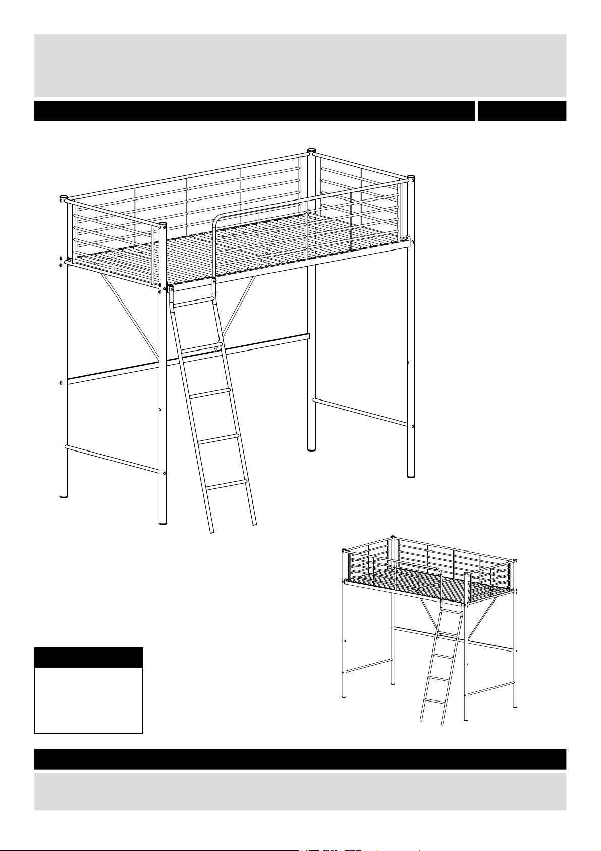
Dimensions
Length - 200cm
Width - 97.5cm
Height - 185cm
If you need help or have damaged or missing parts, call the Customer Helpline: 08456 400800
Issue 1 - 06/01/10
Metal High Sleeper
Page 2

Safety and Care Advice
Important – Please read these instructions fully before starting assembly
1
Important
1) Please note the maximum mattress height is indicated on the corner post inside the opening at the
top of the ladder.
2) This is legal requirement and it is vital that the mattress does not exceed this mark.
3) Maximum thickness of the mattress is 20cm:The top of the mattress shall not come above the line
marked on the bed.
4) All assembly fixings should always be tightened properly.Take care to ensure that no fixings are
loose.
5) Recommended size of the mattress for the top bunk is 90×190cm.
6) The bunk bed should not be used if any structural part is broken or missing.
7) The upper bed of bunk beds are not suitable for children under six years due to the risk of injury
from falls.
8) Children can strangle in items such as ropes, strings, cords, harnesses and belts attached to or
hung on a bunk bed.
Warning
1) Children can become trapped between the bed and wall. To avoid risk of serious injury the distance
between the top safety barrier and the wall shall not exceed 75mm or shall be more than 230mm.
2) The bed complies with EN747-1:2007
• Check you have all the
components and tools listed on
pages 2 and 3.
• Remove all fittings from the
plastic bags and separate them
into their groups.
• Keep children and animals
away from the work area, small
parts could choke if swallowed.
• Parts of the assembly will be
easier with 2 people.
• Place the product on flat and
steady surface during use.
• Keep these instructions for
further use.
• To ensure an easier assembly,
we strongly advise that all
fittings are only finger tightened
during initial assembly. Only
upon completion of the
assembly should all fixing points
be fully tightened.
Mattress height safety notice
• Make sure you have enough
space to layout the parts before
starting.
• Assemble the item as close
to its final position (in the same
room) as possible.
• Assemble on a soft level
surface to avoid damaging the
unit or your floor.
• Dispose of all packaging
carefully and responsibly.
• Safety: To avoid any risk of
suffocation to animals or
children dispose of the plastic
bags immediately.
• Cleaning: As with all surfaces
clean with a damp cloth and
mild detergent, do not use
bleach or abrasive products.
Care and maintenance
• Only clean using a damp cloth
and mild detergent, do no use
bleach or abrasive cleaners.
• From time to time check that
there are no loose screws on
this unit.
• This product should not be
discarded with household
waste. Take to your local
authority waste disposal centre.
Page 3
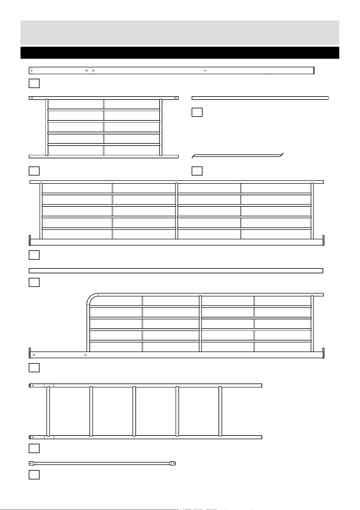
Please check you have all the parts listed below
Components - Parts
2
1
Corner post x 4 (Ø4.5 x 184.7cm)
8
Ladder (151 x 35.7cm)
2
End panel x 2 (97 x 39.8cm)
6
Front guard (191 x 42cm)
Rear guard (191 x 42cm)
9
Slats x 24 (Ø1.6 x 95cm)
4
7
Support x 2 (Ø1.3 x 90cm)
Lower stretcher (long) (190.4 x 3cm)
5
3
Lower stretcher (short) x 2 (Ø1.9 x 88.5cm)
Page 4
Components - Fittings
0
Ruler – Use this ruler to help correctly identify the screws
5
10 2015 4035
30
25 80
75
7060 65
45
50
55
160155150140 145120 125
130 135
85 90 10095 115110105 165 170
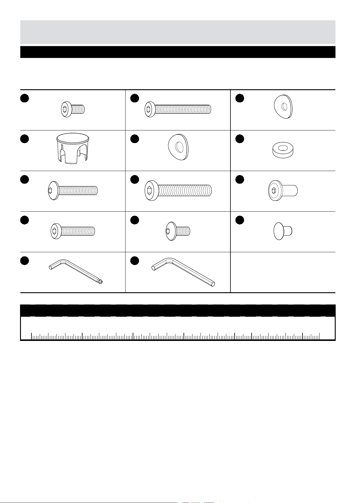
Please check you have all the fittings listed below
Note:
The quantities below are the correct amount to complete the assembly. In some cases more
fittings may be supplied than are required.
If you have damaged or missing components,
call the Customer Helpline: 08456 400800
3
A B C
D E F
G
H
J
K L M
N
P
M6 x 15mm Allen screw x 8 M6 x 65mm Allen screw x 9
Curved washer(small) x 19
M6 x 45mm Screw x 4
M8 x 65mm Allen screw x 4
M6 x 35mm Allen screw x 2
M6 x 10mm Screw x 52
Plastic cap x 4 Curved washer(large) x 8
Rubber washer x 8
Nut x 6
Plastic plug x 6
Allen key x 2 Allen key x 1
Page 5
Step 1
Assembly Instructions
Assembling side
frames
4
Lay two corner posts ,
end panel and short
lower stretcher flat on
the floor as shown.
Note:
The holes in end
panel must be at the
top.
Insert end panel into
the large holes in posts
.
Secure using fixings
and .
Note:
Do not fully
tighten screws .
Assemble short lower
stretcher in between
the corner posts using
fixings and .
Note:
Do not fully
tighten screws .
Insert end caps into
the top of the corner
posts.
Repeat for the other side
frame.
1
Note: Hole at top
Top
Bottom
1
1
1
2
A
C
D
A
C
D
B
C
3
2
2
3
2
2
1
A
C
A
3
B
B
D
C
Page 6
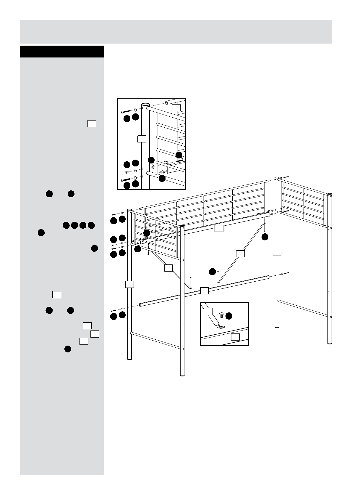
Step 2
Assembling rear guard
5
H
E
B
C
J
E
B
C
B
C
J
E
H
E
G
F
F
1
4
1
1
4
F
G
5
Assembly Instructions
7
5
L
7
7
L
L
Two people are needed
here.
With help, stand both
side frames upright.
Assemble rear guard
in between the side
frames as shown.
Note:
Do not fully tighten
any screws during the
assembly.
Secure at the top using
fixings and as
shown.
Secure at the bottom
using fixings
and as shown.
Note:
Plastic washers
are located in between
the rear guard and the
side frames.
Assemble long lower
stretcher in between
the side frames using
fixings and .
Assemble supports
in between rear guard
and long stretcher
using screws .
4
B C
E F G H
J
F
B C
L
5
7
4
5
Page 7

Step 3
Assembling front guard
At this stage, choose if
you want the ladder on
the right hand side or left
hand side.
According to which side
you want the ladder,
assemble front guard
in between the side
frames as shown.
Secure at the top using
fixings and .
Secure at the bottom
using fixings
and .
6
6
E
E
H
E
J
C
B
G
F
F G H
6
C
B
E
J
E
H
F
G
6
1
Assembly Instructions
Alternative
assembly
F
F
J
B C
Page 8

Step 4
7
Assembly Instructions
Assemble ladder to
front guard using
fixings and .
Note:
fixings are
located inside the frame
as shown.
Attaching ladder
8
J
C K
J
C
K
J
K
C
8
8
6
6
6
J
Page 9

Assembly Instructions
Step 5
Assembling slats
Assembly is complete.
8
Assemble slats using
screws as shown.
Plastic plugs can be
used to cover the un-used
holes in corner posts
as shown.
9
M
L
M
M
M
M
L
L
9
6
M
M
1
9
1
1
If you need help or have damaged or missing parts, call the Customer Helpline: 08456 400800
Home Retail Group. 489-499 Avebury Boulevard. Saxon Gate West. Central Milton Keynes. MK9 2NW
M
M
Page 10

656/0159
Assembly Instructions – Please keep for future reference
Important – Please read these instructions fully before starting assembly
Dimensions
Length - 200cm
Width - 97.5cm
Height - 185cm
If you need help or have damaged or missing parts, call the Customer Helpline: 08456 400800
Issue 2 - 26/06/13
Metal High Sleeper
Page 11

Safety and Care Advice
Important – Please read these instructions fully before starting assembly
1
• Check you have all the
components and tools listed on
pages 2 and 3.
• Remove all fittings from the
plastic bags and separate them
into their groups.
• Keep children and animals
away from the work area, small
parts could choke if swallowed.
• Parts of the assembly will be
easier with 2 people.
• Place the product on flat and
steady surface during use.
• Keep these instructions for
further use.
• To ensure an easier assembly,
we strongly advise that all
fittings are only finger tightened
during initial assembly. Only
upon completion of the
assembly should all fixing points
be fully tightened.
Mattress height safety notice
• Make sure you have enough
space to layout the parts before
starting.
• Assemble the item as close
to its final position (in the same
room) as possible.
• Assemble on a soft level
surface to avoid damaging the
unit or your floor.
• Dispose of all packaging
carefully and responsibly.
• Safety: To avoid any risk of
suffocation to animals or
children dispose of the plastic
bags immediately.
• Cleaning: As with all surfaces
clean with a damp cloth and
mild detergent, do not use
bleach or abrasive products.
Care and maintenance
• Only clean using a damp cloth
and mild detergent, do no use
bleach or abrasive cleaners.
• From time to time check that
there are no loose screws on
this unit.
• This product should not be
discarded with household
waste. Take to your local
authority waste disposal centre.
Important
1) Please note the maximum mattress height is indicated on the corner post inside the opening at the
top of the ladder.
2) This is legal requirement and it is vital that the mattress does not exceed this mark.
3) Maximum thickness of the mattress is 20cm:The top of the mattress shall not come above the line
marked on the bed.
4) All assembly fixings should always be tightened properly.Take care to ensure that no fixings are
loose.
5) Recommended size of the mattress for the top bunk is 90×190cm.
6) The bunk bed should not be used if any structural part is broken or missing.
7) Warning: High beds and the upper bed of bunk beds are not suitable for children under six years
due to the risk of injury from falls.
8) Children can strangle in items such as ropes, strings, cords, harnesses and belts attached to or
hung on a bunk bed.
Warning
1) Children can become trapped between the bed and wall. To avoid risk of serious injury the distance
between the top safety barrier and the wall shall not exceed 75mm or shall be more than 230mm.
2) The bed complies with EN747-1:2012
Page 12

Please check you have all the parts listed below
Components - Parts
2
1
Corner post x 2 (Ø4.5 x 184.7cm)
11
Ladder (151 x 35.7cm)
3
End panel x 2 (97 x 39.8cm)
7
Front guard (191 x 42cm)
Rear guard (191 x 42cm)
9
Slats x 2 (□2 x 1 x 95cm)
5
8
Support x 2 (Ø1.3 x 90cm)
Lower stretcher (long) (190.4 x 3cm)
6
4
Lower stretcher (short) x 2 (Ø1.9 x 88.5cm)
10
Slats x 22 ((□2 x 1 x 95cm)
2
Corner post x 2 (Ø4.5 x 184.7cm)
Smaller diameter
Page 13

Components - Fittings
Please check you have all the fittings listed below
Note:
The quantities below are the correct amount to complete the assembly. In some cases more
fittings may be supplied than are required.
If you have damaged or missing components,
call the Customer Helpline: 08456 400800
3
A B C
D E F
G
H
J
K L M
N
P
M6 x 15mm Allen screw x 8 M6 x 65mm Allen screw x 9
Curved washer(small) x 19
M6 x 45mm Screw x 4
M8 x 65mm Allen screw x 4
M6 x 35mm Allen screw x 2
M6 x 10mm Screw x 52
Plastic cap x 4 Curved washer(large) x 8
Rubber washer x 8
Nut x 6
Plastic plug x 6
Allen key x 2 Allen key x 1
0
5
10 15 20 25 30 35 40
45
50
55
60 65 70
75
80 85 90 95 100 105 110 115 120 125 130 135 140 145 150 155 160 165 170
0
0 5 10 15 20 25 30 35 40 45 50 55 60 65 70 75 80 85 90 95 100 105 110 115 120 125 130 135 140 145 150
1 2
3
4
5 6
Ruler/tape
measure
Ruler - Use this ruler to help correctly identify the screws
Tools required
Foot x 2
Q
Page 14

Step 1
Assembly Instructions
Assembling side
frames
4
Lay front corner post
,rear corner post , end
panel and lower
stretcher flat on the
floor as shown.
Note:
The holes in end
panel must be at the
top.
Note:
The bottom of rear
corner post is smaller
diameter.
Insert end panel into
the large holes in posts
.
Secure using fixings
and .
Note:
Do not fully
tighten screws .
Assemble short lower
stretcher in between
the corner posts using
fixings and .
Note:
Do not fully
tighten screws .
Insert end caps into
the top of the corner
posts.
Repeat for the other side
frame.
1
Note: Hole at top
Top
Bottom
2
1
2
3
A
C
D
A
C
D
B
C
4
3
2
3
3
3
2
A
C
A
4
B
B
D
C
Smaller end
Rear
Front
4
2
C
B
2
4
Page 15

Step 2
Assembling rear guard
5
H
E
B
C
J
E
B
C
B
C
J
E
H
E
G
F
F
2
5
2
2
5
F
G
6
Assembly Instructions
8
6
L
8
8
L
L
Two people are needed
here.
With help, stand both
side frames upright.
Assemble rear guard
in between the side
frames as shown.
Note:
Do not fully tighten
any screws during the
assembly.
Secure at the top using
fixings and as
shown.
Secure at the bottom
using fixings
and as shown.
Note:
Plastic washers
are located in between
the rear guard and the
side frames.
Assemble long lower
stretcher in between
the side frames using
fixings and .
Assemble supports
in between rear guard
and long stretcher
using screws .
With help, fit feet to
corner posts at the
rear of the bunk.
5
B C
E F G H
J
F
B C
L
6
8
5
6
N
2
Feet to extend to rear.
N
2
N
Page 16

Step 3
Assembling front guard
At this stage, choose if
you want the ladder on
the right hand side or left
hand side.
According to which side
you want the ladder,
assemble front guard
in between the side
frames as shown.
Secure at the top using
fixings and .
Secure at the bottom
using fixings
and .
6
7
E
E
H
E
J
C
B
G
F
F G H
7
C
B
E
J
E
H
F
G
7
1
Assembly Instructions
Alternative
assembly
F
F
J
B C
Page 17

Step 4
7
Assembly Instructions
Assemble ladder to
front guard using
fixings and .
Note:
fixings are
located inside the frame
as shown.
Attaching ladder
11
J
C K
J
C
K
J
K
C
11
11
7
7
7
J
Page 18

Assembly Instructions
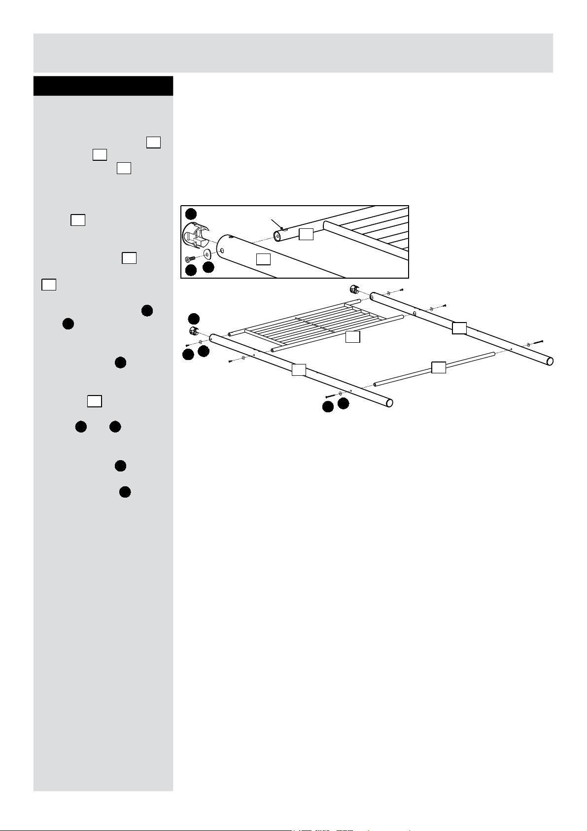
Step 5
Assembling slats
8
Fit slats in the very last
fixing holes at each end of
the bed.
Note:
The arrow labels on
slats must point
outside.
Note:
Slats have been
labelled for easier
identification.
Assemble slats using
screws as shown.
Plastic plugs can be
used to cover the un-used
holes in corner posts
as shown.
10
M
L
M
M
L
10
7
1
9
Slats at
each end
9
2
Arrow label to
point outside
9
9
9
1
M
M
M
M
1
10
L
L
L
L
9
If you need help or have damaged or missing parts, call the Customer Helpline: 08456 400800
Home Retail Group. 489-499 Avebury Boulevard. Saxon Gate West. Central Milton Keynes. MK9 2NW
Assembly is complete.
 Loading...