

Page 1
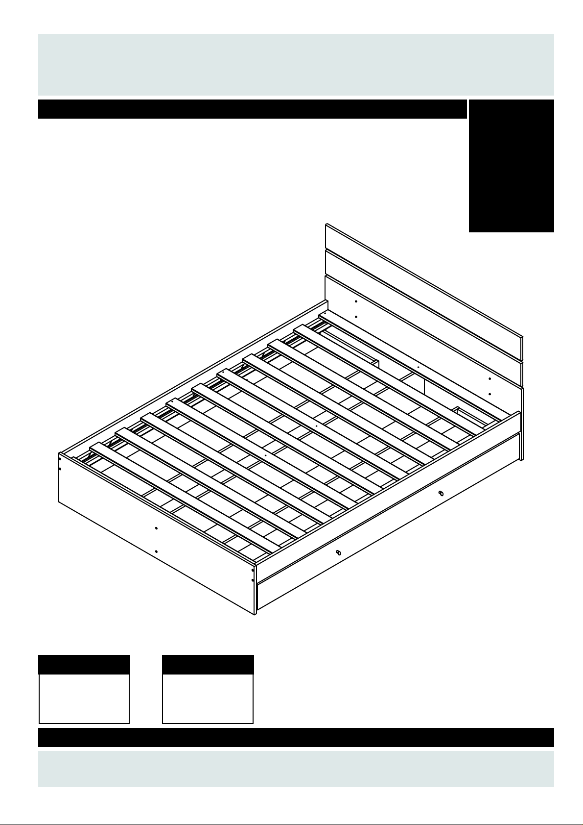
Toronto Double & King
Assembly Instructions - Please k eep for future reference
697/0842
697/0756
697/0811
697/0787
697/0794
697/0859
697/0763
697/0828
Dimensions
Width - 140.5cm
Length - 190cm
Height - 85cm
Dimensions
Width - 156cm
Length - 205cm
Height - 85cm
Issue 2 - 30/01/2014
Important - Please read these instructions fully before starting assembly
If you need help or have damaged or
missing parts, call the Customer Helpline: 01242 621266
Page 2

Safety and Care Advice
Important–Please read these instructionsfully before starting assembly
•
Check you have all the
components and tools listed
on pages 2 and 3.
• Remove all ?ttings from the
plastic bags and separate them
into their groups.
• Keep children and animals
away from the work area, small
parts could choke if swallowed.
• Make sure you have enough
space to layout the parts before
starting.
• Do not stand or put weight
on the product, this could
cause damage.
• Assemble the item as close
to its ?nal position (in the same
room) as possible.
• Assemble on a soft level
surface to avoid damaging
the unit or your ?oor.
the unit or your ?oor.
• Parts of the assembly will
be easier with 2 people.
as this could damage the unit.
Only use hand screwdrivers.
• Dispose of all packaging
carefully and responsibly.
Glue safety - Take care when using glue, please follow the advice below
• Skin contact: Remove
contamination by washing with
soap and water.This procedure
should also be followed prior to
eating and drinking.
• Eye contact: Rinse immediately
with clean water for 15minutes
and seek medical advice.
• If swallowed: Seek medical
advice immediately.
• We do not
recommend the
use of power
drill/drivers for
inserting screws,
Care and maintenance
• Only clean using a d amp cloth
and mild detergent, do not use
bleach or abrasive cleaners.
• From time to time check that
there are no loose screw son
this unit.
• This product should not be
discarded with household
waste. Take to your local
authority waste disposal centre.
Note: This assembly
instruction covers a number of
different sizes of bed.
Although your bed may
appear different to the model
shown the assembly
procedure remains identical.
1
Page 3
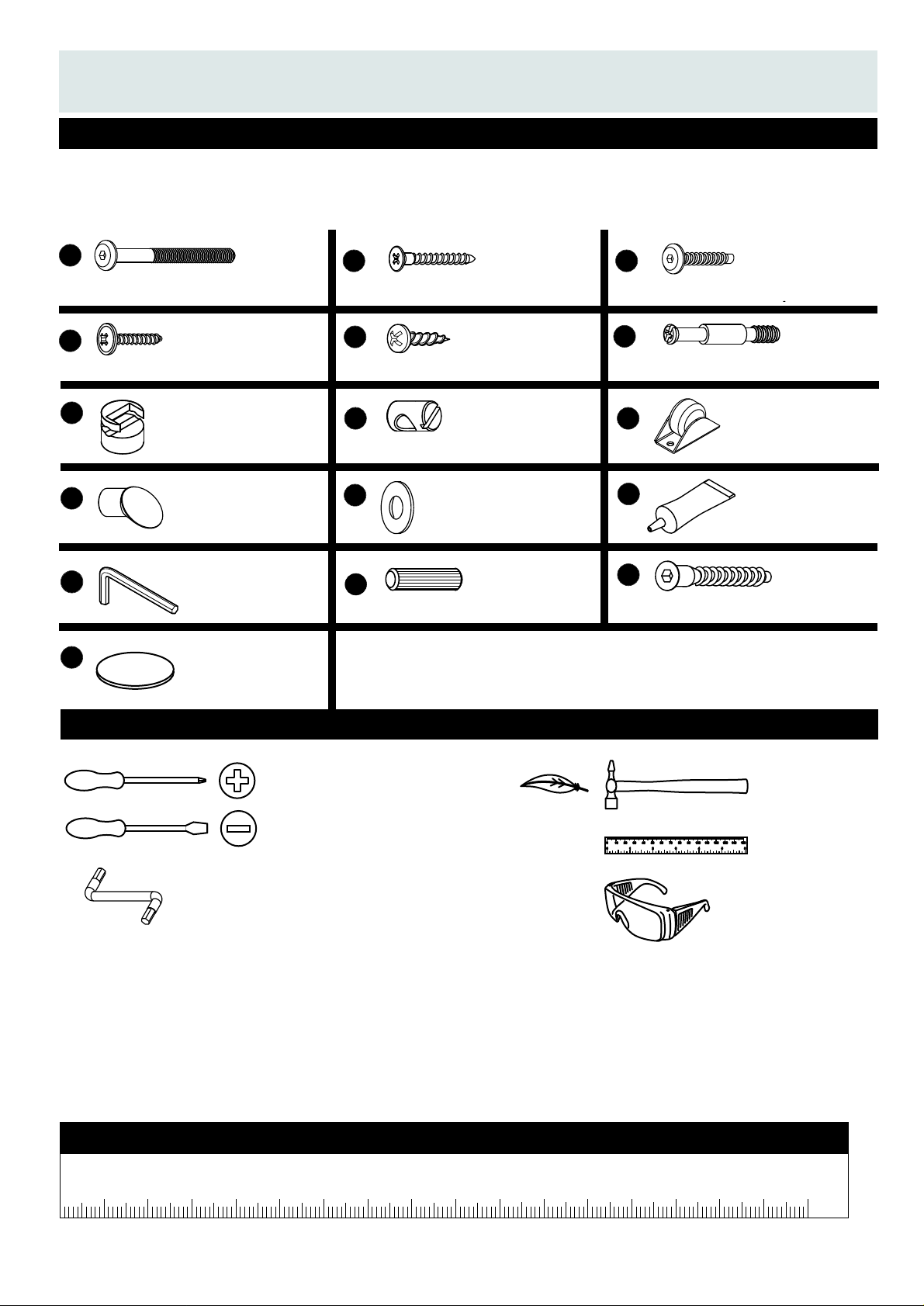
Components-Fittings
If you have any damaged or
missing parts, call our Customer Helpline: 01242 621266
Please check you have all the ?ttings listed below
Note:The quantities below are the correct amount to complete the assembly. In some cases more
?ttings may be supplied than are required.
A
60mm Allen Bolt x 8
D
B
35mm CS Screw x 8
E
4mm x 25mm Screw x 4 15mm Round Head screw x 28
G
12mm CAM Lock
H
x 20
M6 Cross dowel x 8
J
M
Silver Handle
x 4
Allen Key
x1
P
Self Adhesive
K
Small Metal Washer
N
Wooden dowel x 16
x 12
Cover Cap
x 2
C
25mm Allen Screw x 4
F
CAM Peg x 20
I
Castor
x 10
L
15ml Glue Tube
x 1
O
O
45mm Confirmat x 4
Tools required
Cross Headed Screwdriver
Flat Headed Screwdriver
Allen Key
(Supplied)
Ruler - Use this ruler to help correctly identify the fixings
0 10 20 30 40 50 60 70 80 90 100 110 120 130 140 150
0 1 2 3 4 5 6
Small
hammer
Ruler/tape
measure
Eye protection
(when using a
hammer or glue)
05 10 15 20 25 30 35 40 45 50 55 60 65 70 75 80 85 90 95 100 105 110 115 120 125 130 135 140 145 150 155 160 165 170
2
Page 4
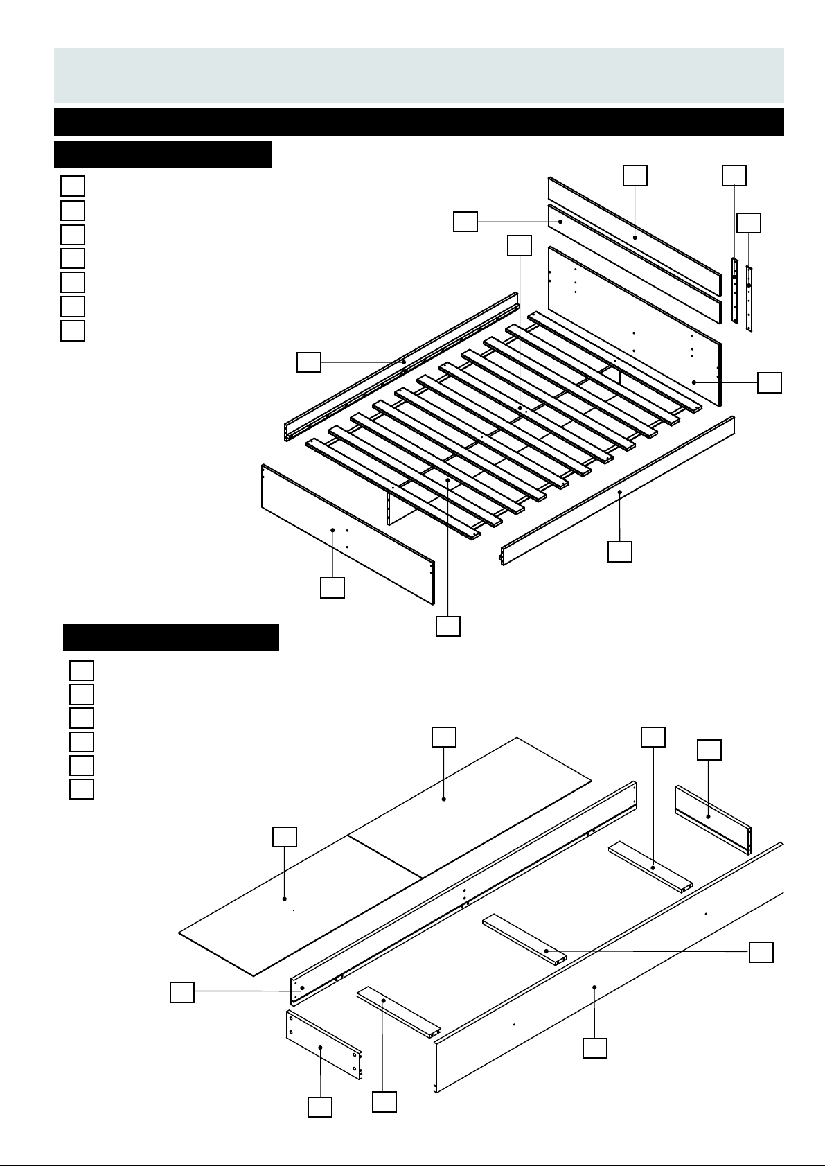
Components-Panels
Please check you have all the panels listed below
Side Rails x 2
1
Toe End Panel x 1
2
Head End Panel x 1
3
Headboard Struts x 2
4
Headboard Rails x 2
5
Centre Rail x 1
6
Roll of Slats x 1
7
5
5
7
1
1
4
4
3
Underbed drawer Panels
Drawer Base x4
8
Drawer Side x4
9
Support Rails x4
10
Centre Support Rail x1
11
12
Drawer Back x2
Drawer Front x2
13
2
6
8
8
10
9
11
12
13
9
10
3
Page 5

Assembly Instructions
Step 1
Fitting the side rails
and centre rail to the
head end panel
Position the side rails
as shown and fit 4 x M6
Cross dowels in to
H
the side rails. Note that
the slot must be aligned
as shown in the diagram.
Next fit the M6 x 60 bolts
A
through the head end
and in to the ends of the
side rails. Use the 4mm
Allen key to tighten the
bolts in to the cross
dowels.
Next position the centre
rail as shown and fix
6
to the head end panel
using 2 x 45mm
Confirmat screws
A
H
1
6
3
O
O
H
H
Note the correct
alignment of the
Cross Dowel slots
1
A
A
H
H
6
1
3
H
H
O
O
A
A
x 4 x 4
x 4 x 4
x 2
Step 2
Fitting the side rails
and centre rail to the
toe end panel
2
Position the toe end
as shown and fit 4 x M6
Cross dowels in to
H
the side rails. Note that
the slot must be aligned
as shown in the diagram.
Next fit the M6 x 60 bolts
A
through the toe end
and in to the ends of the
side rails. Use the 4mm
Allen key to tighten the
bolts in to the cross
dowels.
Next fit the centre rail
to the toe end panel
using 2 x 45mm
Confirmat screws
1
6
A
6
2
Please note the postition
of the battens on the side rails
1
H
A
A
O
O
H
2
A
A
H
H
6
1
4
Page 6

AssemblyInstructions
Step 3
Fitting the headboard
struts to the head
board rails
Position the headboard
rails and headboard
struts as shown.
Fix the struts to the rails
using 8 x 15mm round
head screws
Note that the pilot holes
on the headboard rails
are offset - see diagram
below.
4
5
E
E
x 8
Note offset
pilot holes
in the
headboard
rails
E
Pilot Holes
a
b
b
a
E
E
Pilot Holes
4
5
E
5
4
Step 4
Fitting the headboard
assembly to the head
end panel
Fix the assembled
headboard on to the
back of the head end
panel using 4 x 25mm
Allen screws and 4 x
metal washers .
Note that there are 6
holes in the head end
panel. Please use the
top 4 holes to fit the
struts as shown in the
detail view.
3
C
K
C
K
K
C
C
C
K
K
K
x 4
x 12
5
Page 7

Assembly Instructions
Step 5
Fitting the roll of slats
7
to the side rails.
Open the roll of slats
and lay them on the
side rails as shown.
Pull the end slats out
so that they touch the
head end panel and
the toe end panel.
Secure each corner
using 4 x 35mm screw
The side rails may be
slightly bowed out. If so
push them in on both
sides before fitting the
last 4 x 35mm screw
B
B
B
B
B
B
B
B
7
B
B
B
B
B
6
x 12
Step 6
Fitting the wooden
dowels to the
support rails and the
CAM Lock to the
Centre Support Rail
as shown.
Put a small amount of
glue in to the holes and
gently tap the wooden
dowels in to the support
rails as shown.
Wipe off any excess
glue with a damp cloth
N
10
G
11
Push Push
G
L
N
G
11
10
10
N
L
N
N
L
N
N
x 8
G
x 2
L
L
Glue the dowels
in place
6
Page 8
Assembly Instructions
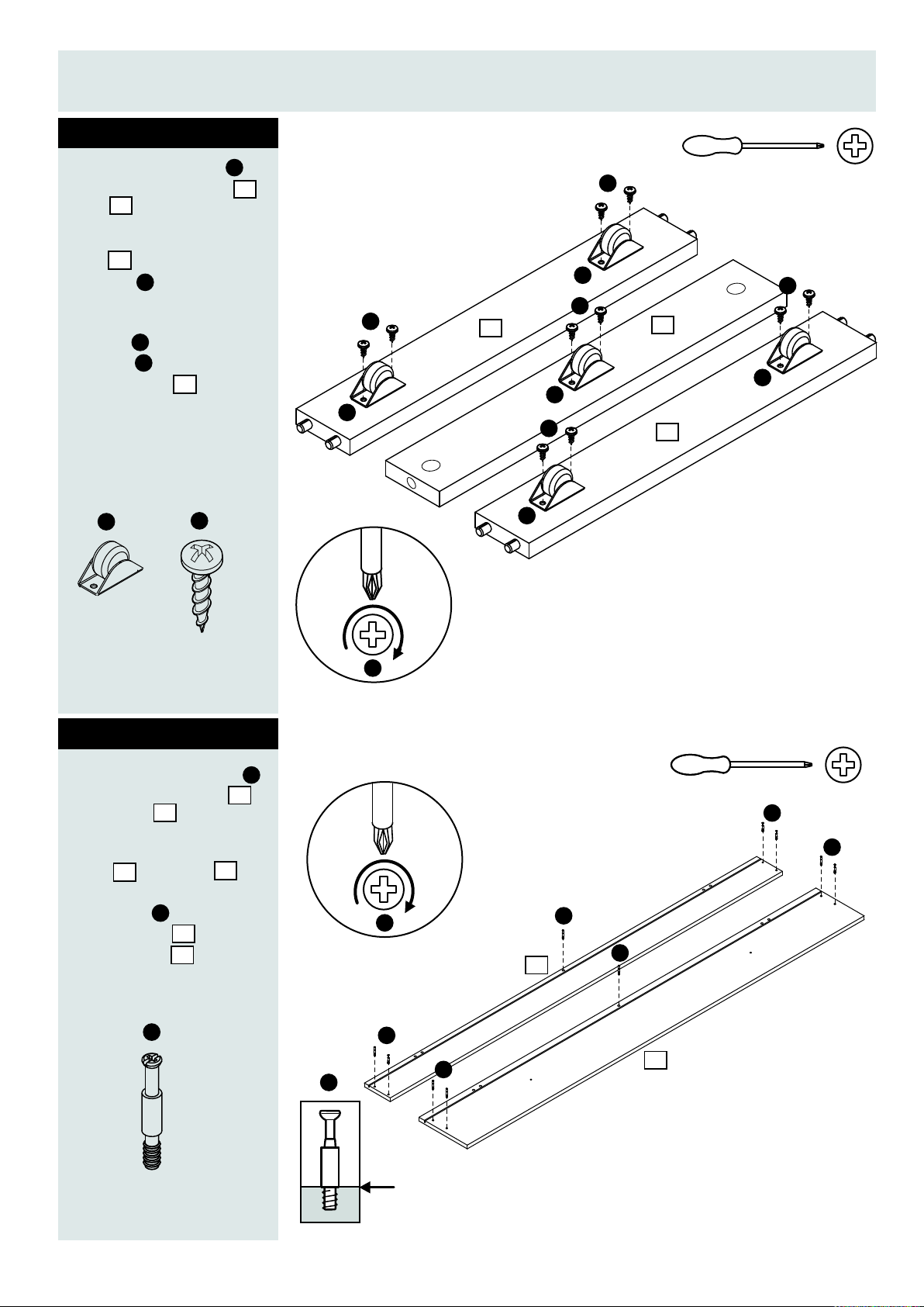
Step 7
Fitting the castors
to the support rails
11
and
Position the support
10
rails and the
castors as shown.
I
Using the round head
screws fix the
castors to the
support rails as
E
I
10
shown.
I
E
x 5
I
10
x 10
E
I
E
E
I
10
I
E
I
11
10
E
I
Step 8
Fitting the cam pegs
to the drawer back
13
13
12
F
12
13
F
x 10
and front.
Position the drawer
front and back
as shown. Attach the
cam pegs to the
drawer back and
drawer front
12
E
F
F
F
12
F
F
13
F
F
F
F
The cam fixing pegs should be
screwed down to this shoulder
7
Page 9

Assembly Instructions
Step 9
Fitting the support
11
10
rails + and drawer
12
9
N
9
10
11
10
12
Glue the dowels
L
in place
9
sides to the drawer
front
Position the drawer
sides and the
support rails +
as shown. Put a small
amount of glue into
the holes and gently
tap the support rails
into the drawer front
as shown.
Wipe off any excess
glue with damp cloth.
10
9
10
G
L
11
L
13
Attach the cam lock
fix the drawer sides
to the drawer front
G
9
13
and the Centre Support
11
Rail as shown.
Do not assemble the
drawers if the dowels
are not glued.
G
x 4
Step 10
Fitting the drawer
bases and the
drawer back
Position the drawers
as shown. Put a small
amount of glue into the
holes and gently tap the
drawer back to the
support rails as shown.
Wipe off any excess of
glue with damp cloth.
Slide the drawer bases
in to the drawer sides
and drawer front
Attach the cam lock
fix the drawer back
to the drawer sides.
8
12
12
9
13
G
12
9
G
N
L
Glue the dowels
in place
L
G
9
G
Note use plenty of glue
12
8
13
G
L
G
9
8
L
castor mount.
x 4
1
2
3
4
CAM FIXING STEPS
8
Page 10

Assembly Instructions
Step 11
Fitting the handles
to the drawer front
Position the drawer as
shown. Use 2 x screw
to fix the silver
D
handle to the drawer
front as shown.
Repeat the above for
the second drawer unit
J
D
x 4
J
13
J
x 4
D
13
D
J
x 2
J
Step 12
Fitting the screw cover
caps and the underbed
drawers.
Fit 2 x self adhesive
cover caps to the
heads of the centre rail
screws as shown.
Finally push the drawer
units under the side rails.
The assembly is now
complete.
P
P
x 2
missing parts, call our Customer Helpline: 01242 621928
P
If you need help or have damaged or
9
 Loading...