

Page 1
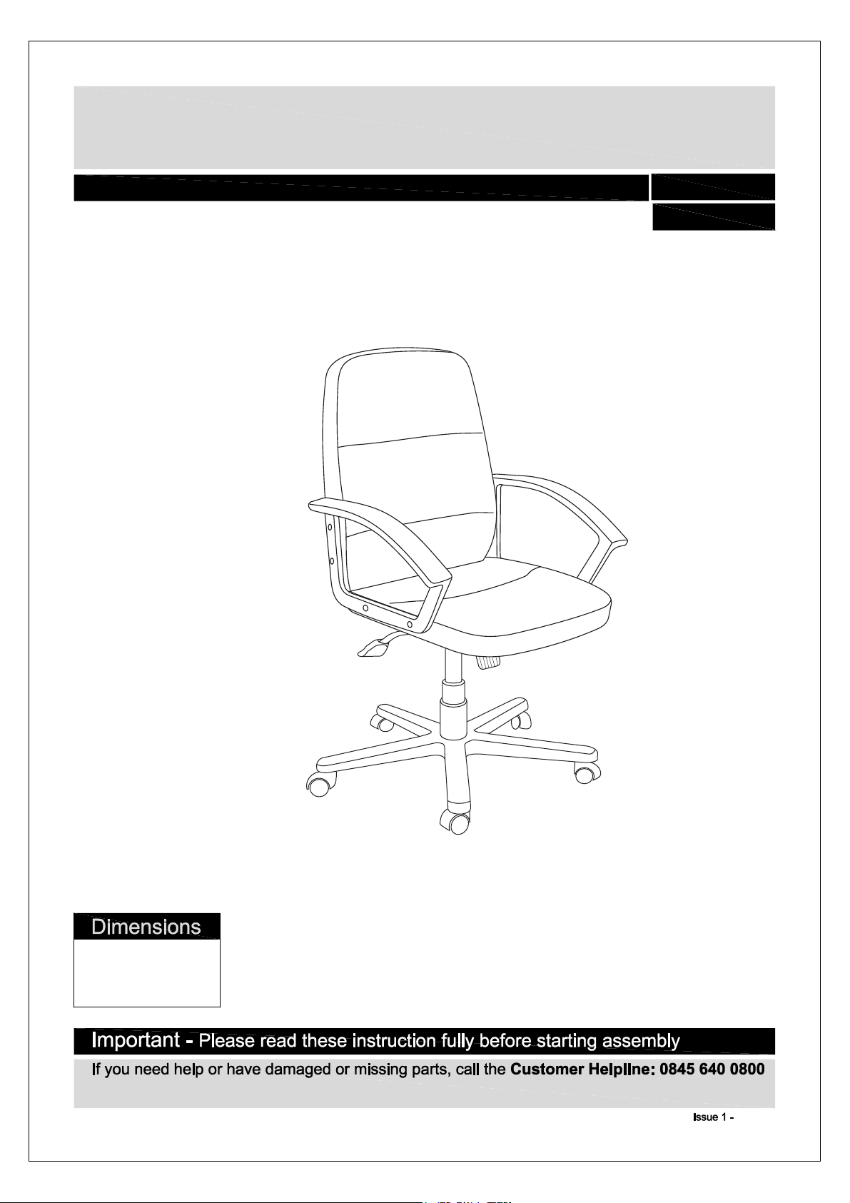
Brixham Leather Eff Managers Chair
Assembly Instructions - Please keep for future reference
617/9131
617/3618
Width-60cm
Depth-62cm
Height-92 - 104cm
06/03/14
Page 2
Safety during use
.
Do not stand on chair. Do not
use this chair as a step ladder.
.
At least every 4 months, check all
bolts, screws and knobs, to be sure
they are tight.
.
Use this product only for seating
one person at a time
.
If parts are missing, broken,
damaged or worn, stop using this
product until repairs are made.
Use only factory authorised parts.
.
Do not use this chair unless all
bolts, screws and knobs are firmly
secured.
.
Failure to follow these warnings
could result in serious injury.
Page 3
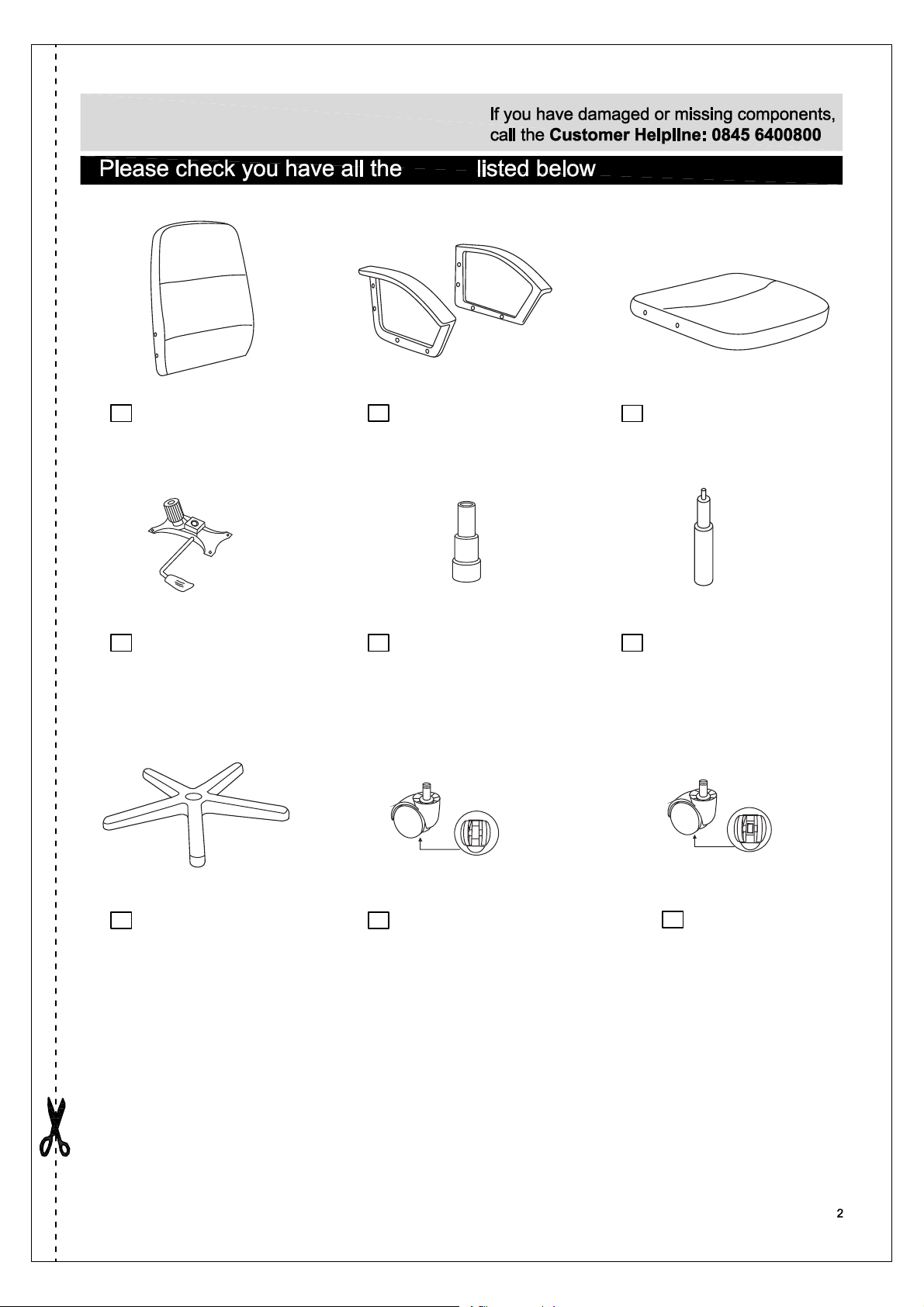
Components - Parts
parts
1 2 3
Backrest
(470x570x65mm)
Armrest x2
(430x250x60mm)
Seat
(480x485x65mm)
4 5 6
Mechanism
(248x173mm)
Star base
7 8
(R300mm)
Telescoping cover
(Ф75x320mm)
Normal castor x3
(Ф50mm)
Gas lift
(Ф50x210mm)
Brake castor x2
9
(Ф50mm)
Page 4
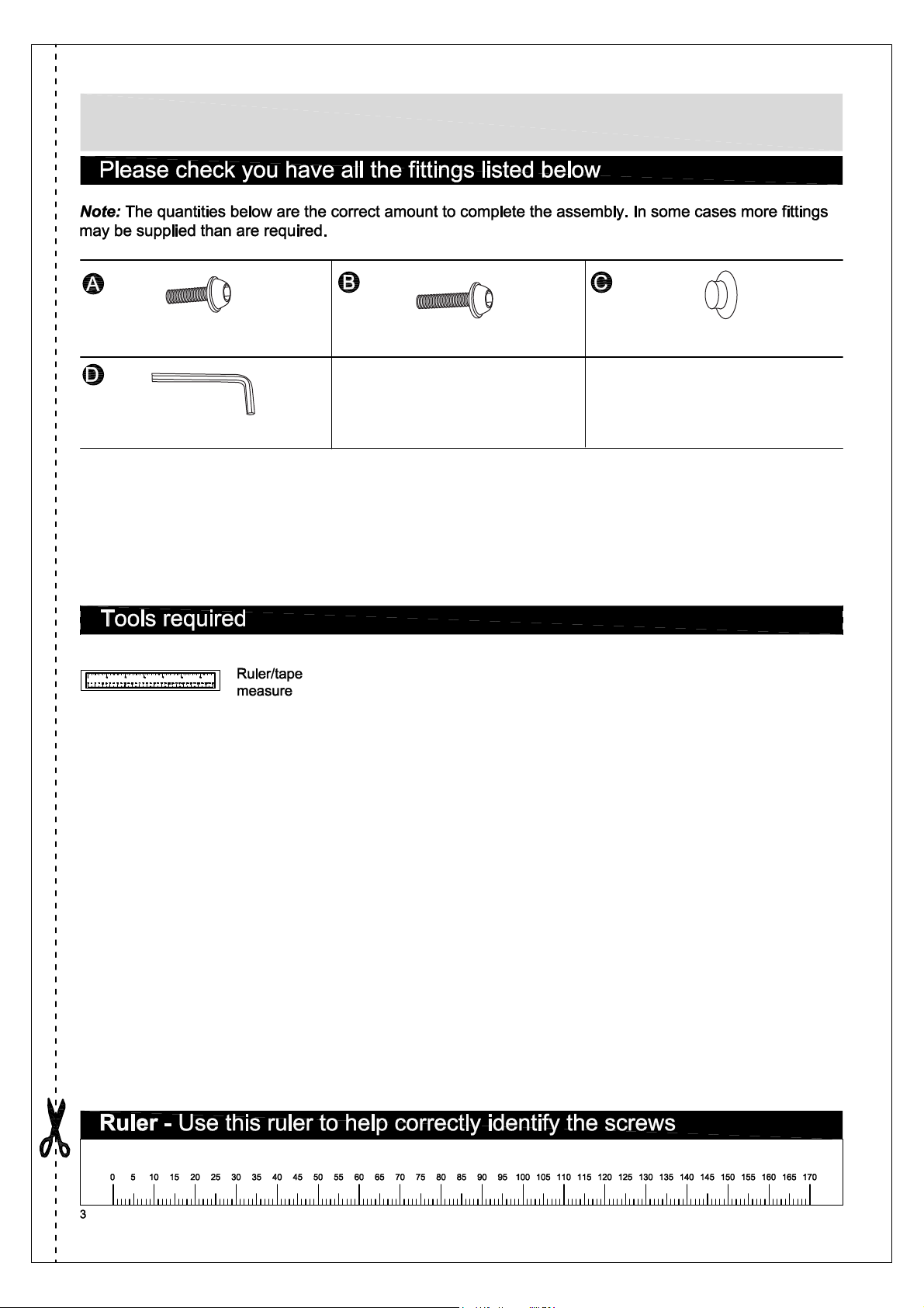
Components - Fittings
M6x16mm bolt x4
5mm Allen key x1
M6x20mm bolt x8 Ф15x9mm cap x8
Page 5

Attaching castors
a
:Insert castors and
into star base .
9
9
Making sure they are
in alternate positions
on the base.
:Turn star base over
b
and place it on the floor.
Insert gas lift into the
center hole of star base
.
7
8
7
7
6
a:
b:
8
9
9
8
8
7
6
c:Place telescoping
cover over the
gas lift .
5
6
c:
7
5
6
Page 6

Attaching armrests
Attach two armrests to
seat with bolts
3
using allen key
B
.
D
2
Step 3
2
B
2
B
D
B
B
3
Assembling the backrest
Assemble armrests to
backrest with bolts .
1
2
1
2
2
Page 7

Use cap to cover the
hole of arms .
c
2
C
C
Attaching mechanism
Attach mechanism to
seat with
bolts .
C
C
C
C
C
C
4
3
Page 8
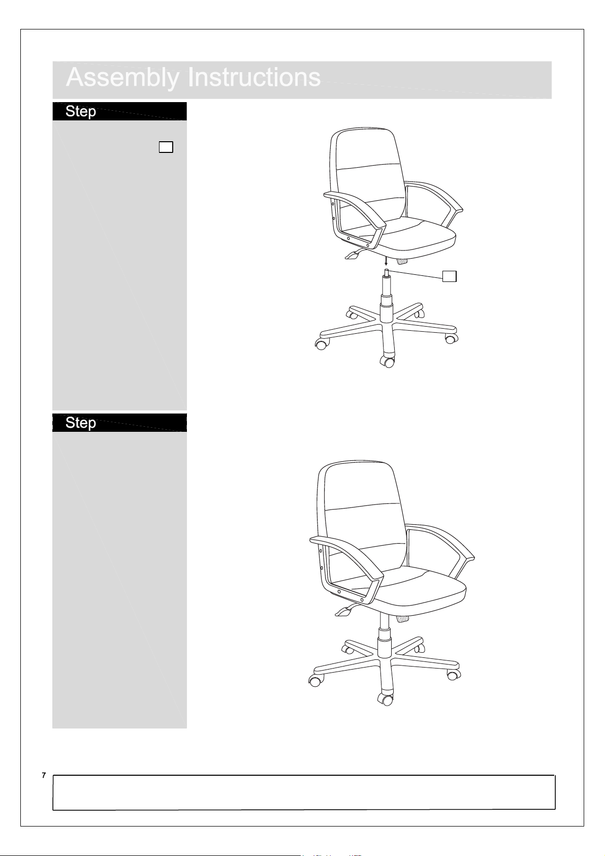
6
Place the seat unit onto
the top of the gas lift .
6
6
7
Assembly is complete.
If you need help or have damaged or missing parts, call the Customer Helpline: 0845 640 0800
Page 9

Components
A
1 x Backrest
1 x Seat Support
D
1 x Seat Cushion
B
E
1 x Base
1 x Left Armrest
C
1 x Right Armrest
F
I
8 x Plastic Plug
Hi Back Leather Mix Manager's Chair
Simple Assembly Instructions - Please keep for future reference
1 x Gas Lift
G
Fittings
A
8 x Long Screw
1 x Cover
H
4 x Screw
B
J
5 x Castor
1 x Hex Key
C
IMPORTANT
1. Read these instructions carefully and
familiarise yourself with the procedure
before assembling the unit.
2. Check that you have all the component
parts following the list on the back
cover and familiarise yourself with
11-02
each part before proceeding.
3. Take all the fittings out of the plastic bag
and separate them into their groups.
4. Ensure you have enough space to lay out
all the parts before assembly.
5. To avoid scratching it is recommended
that you assemble the unit on a soft
level surface.
Page 10

Assembly Instructions
Assembly Instructions
Stage 1 – The Base
1. Place all the five Castors J in the
holes located under Base E . See
fig. 1.
2. Put Gas Lift G in the Base unit.
Then slide the Cover H over the
top. See fig. 2.
NOTE: Make sure the Metal Support
is fixed tight and is fully
inserted.
Stage 2 -
The Seat
Cushion
Stage 3 – Finishing the Unit
J
1. Use the Screw A to fix the
fig. 1
E
H
G
fig. 2
B
D
Backrest A in the Armrest. Then
use the Plastic Plug I to cover
the Screws. See fig. 5.
NOTE: It would be useful to ask
someone to help you at this
stage.
2. Put the Seat Cushion onto the
Base Unit. See fig. 6.
NOTE: This part can no longer be
disassembled.
3. Finally carefully place the chair in
the desired location. See fig. 7.
fig. 5
I
A
fig. 6
1. Use the Screw B to fix the Seat
Support D into the Seat Cushion
B. See fig. 3.
2. Use the Screw A to fix the Left
Armrest C and Right Armrest F
into the Seat Cushion. Then use
Plastic Plug I to cover the Screws.
See fig. 4.
fig. 4
B
fig. 3
F
C
I
A
I
A
Care and Maintenance
Safety
To avoid any risk of suffocation to animals or children dispose of the plastic
bags immediately.
Cleaning
As with all surfaces clean with a damp cloth and mild detergent, do not use bleach
or abrasive products.
Fitting
From time to time check to ensure the screws are ridged.
fig. 7
Page 11

Page 12

 Loading...