

Page 1
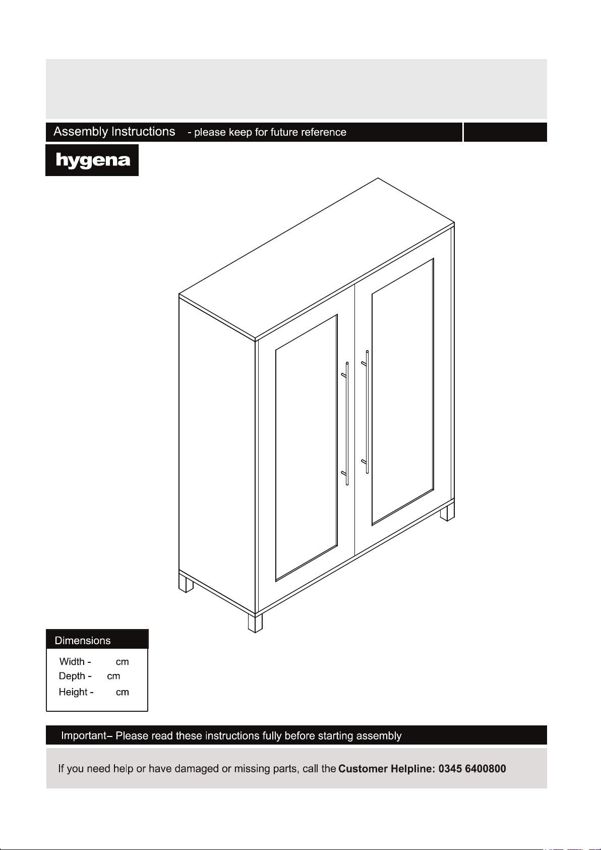
Lydiard Gloss White Large Shoe Cabinet
617/5599
91.5
35
115
Issue 2 - 31/10/2016
Page 2
Safety and care advice
3
Handy Hints
• Assemble all parts and bolts
loosely during assembly, only
once the product is complete
should you fully tighten the bolts
• Regularly check and ensure
that all bolts and ttings are
tightend properly.
1
Page 3
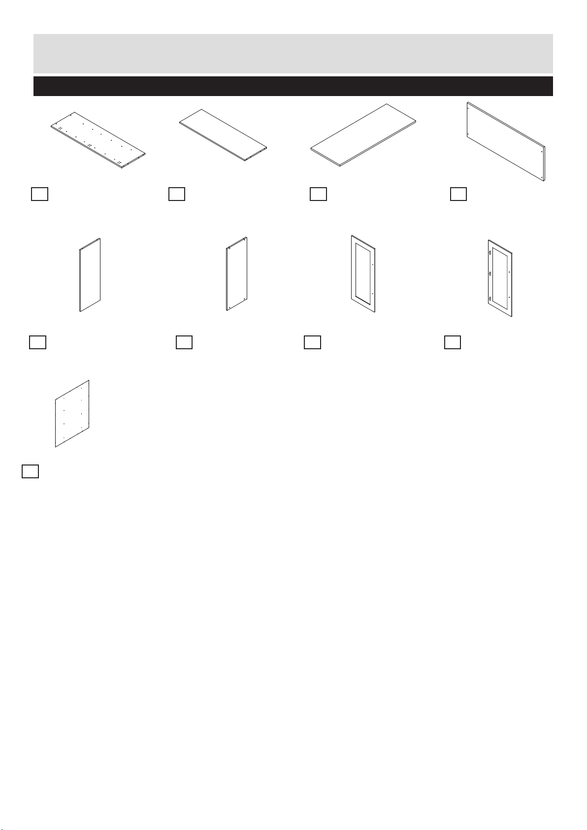
Components - Panels
Please check you have all the panels listed below
1
Left Side Panel x 1
(H104.5cm x W34.2cm)
5
Shelf Panel 5 x 4
(H88.5cm x W32.7cm)
9
Back panel
(H106cm x W90cm)
2
Right Side Panel x 1
(H104.5cm x W34.2cm)
6
Shelf Panel 6 x 2
(H88.5cm x W32.7cm)
3
Top Panel x 1
(H91.5cm x W35cm)
7
Left Door x 1
(H104.5cm x W44.3cm)
4
Base Panel x 1
(H91.5cm x W35cm)
8
Right Door x 1
(H104.5cm x W44.3cm)
2
Page 4
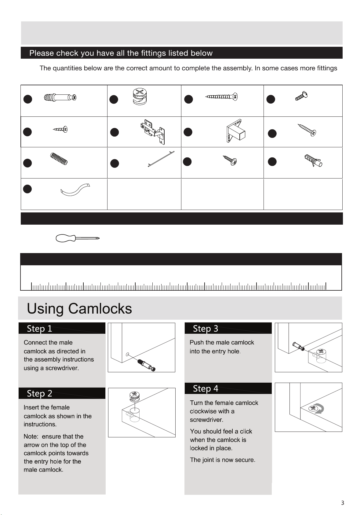
Components - Fittings
Note:
may be supplied than are required.
A
A
A
B
B
B
C
C
C
35mm Screw x 6
D
D
D
15mm Screw x 435mm Male Camlock x 12 Female Camlocks x 12
E
E
E
D
12mm Screw x 36
E
E
I
D
Dowels x 20
M
Wall Strap x 2
F
F
F
D
Hinges x 6
F
J
F
D
Handle x 2
F
G
G
G
D
Feet x 4
K L
16mm Screw x 24
Tools required
Phillips screwdriver
(medium & large)
Ruler – Use this ruler to help correctly identify the screws
105
0 5 10 15 20 25 30 35 40 45 50 55 60 65 70 75 80 85 90 95 100
110 115 120 125 130 135 140 145 150 155 160 165 170
G
H
25mm Screw x 16
Wall Plug x 2
Page 5
Assembly Instructions
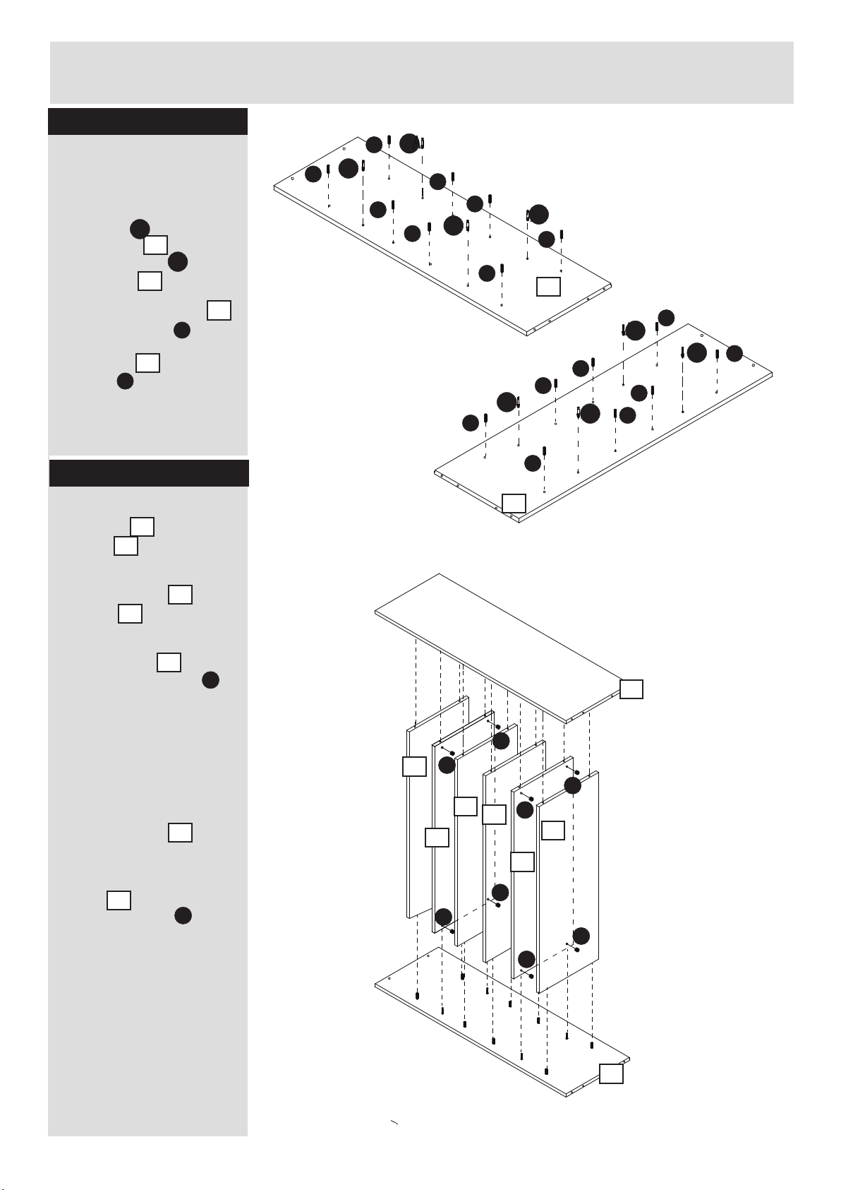
Step 1
I
Inserting Male Camlocks
and Dowels
1. Insert 4 x Male
Camlocks A into Left
Side Panel 1 and 4 x
Male Camlocks A into
Side Panel 2 .
2. Into Left Side Panel 1
insert 8 x Dowels I in
position shown. Into Right
Side Panel 2 insert 8 x
Dowels I in positions
shown
A
1
A
2
1
I
2
I
A
I
I
A
I
I
A
I
I
A
I
1
I
A
A
I
I
I
A
I
A
I
I
Step 2
1. Onto the Dowels in Left
Side panel 1 locate 4 x
Shelves 5
2. Onto the Male Camlocks
in Left side panel 1 locate
2 x Shelf 6
3. Into holes in the underside
of 2 x Shelves 6 insert
4 x Female Camlocks B.
Use a screwdriver to turn the
Female Camlocks
Clockwise to lock
For more information refer to
the Using Camlocks Section
4. Onto Shelf panels, locate
Right Side Panel 2.
5. Into Holes shown in the
underside of 2 x Shelf
Panels 6 insert 4 x
Female Camlocks B
Use a screwdriver to turn the
Female Camlocks
Clockwise to lock
1
5
1
6
6
B
2
6
B
I
2
2
B
B
5
B
5
6
B
5
5
6
B
B
B
B
For more information refer to
the Using Camlocks Section
4
1
Page 6
Assembly Instructions
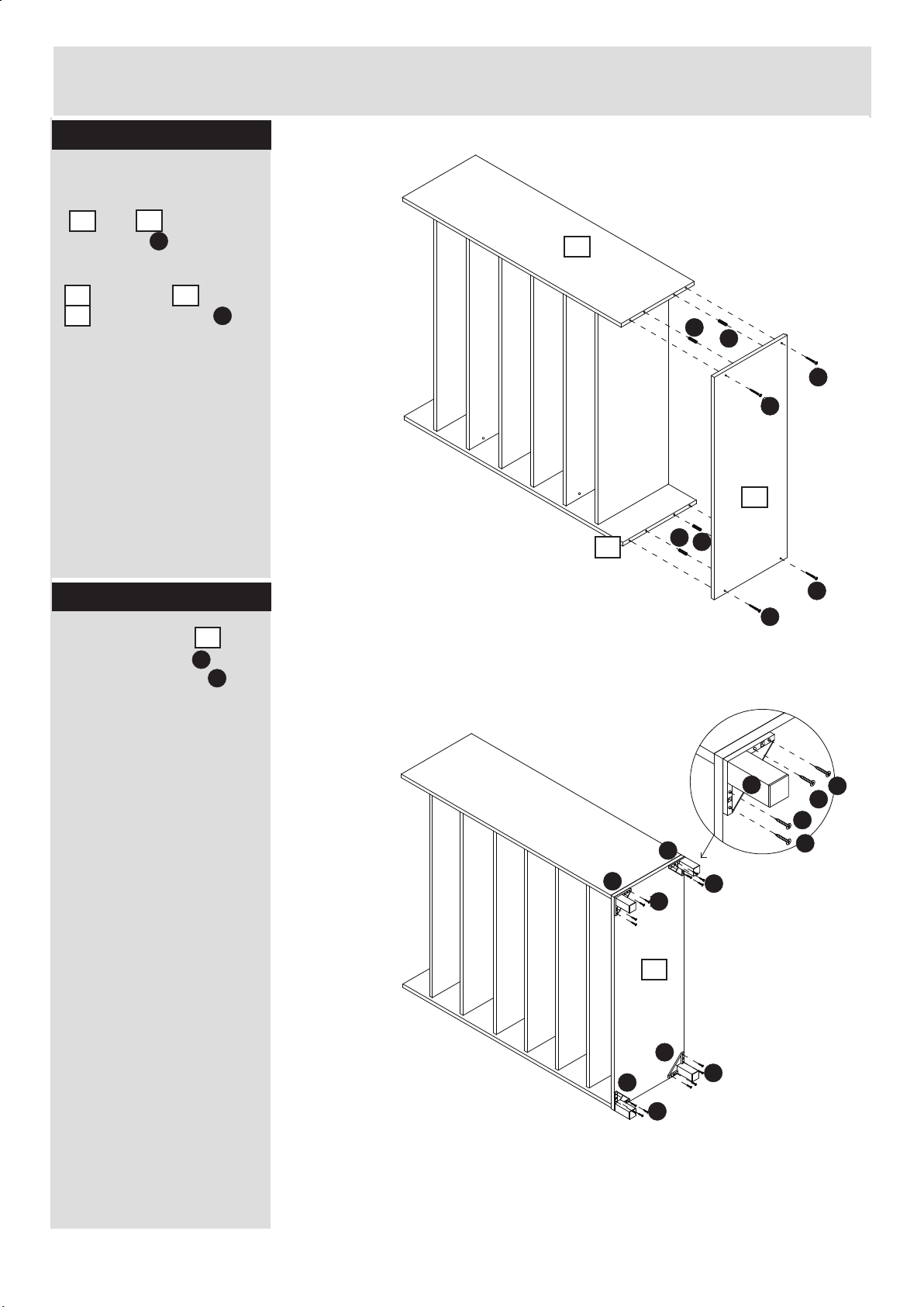
Step 3
1. Into the ends Left
and Right Side Panels
1 and 2 insert
1
4 x Dowels I .
2. Connect Base Panel
4 to Panels 1 and
4
2 using 4 x Screw C
2
2
I
1
C
2
I
I
C
C
4
I
1
I
Step 4
1. To Base Panel 4
connect 4 x Feet G
using 4 x Screws H
per Foot
4
G
H
C
C
G
G
G
H
H
H
H
H
H
4
G
G
H
H
5
Page 7
Assembly Instructions
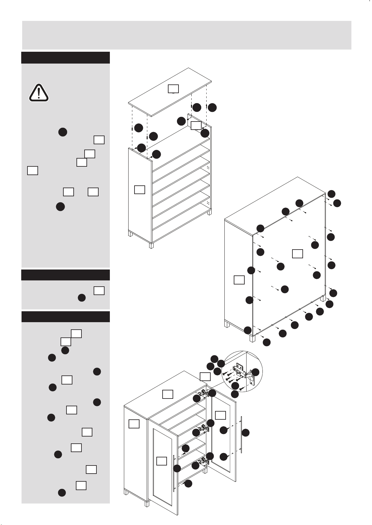
Step 5
Lift the unit to its feet
Warning:
The unit
is heavy.
Lift with care.
1. Insert 4 x Male
Camlocks A into the
underside of Top panel 3
2. Locate Top panel 3
onto Side Panels 1 and
2 .
2
3. Into Holes shown in
Side Panels 1 and 2
insert 4 x Female
Camlocks B.
Use a screwdriver to turn
the Female Camlocks
Clockwise to lock
For more information refer
to the Using Camlocks
Section
A
3
3
1
1
2
B
Step 6
1. Connect Back panel 9
using 22 x Screw K
9
K
Step 7
1. To Left Door 7 and
Right Door 8 Connect
2 x Handle J Using 2 x
Screw D per Handle.
2. Connect 3 x Hinges F
to Left Door 7 using 2 x
Screw E per Hinge.
3. Connect 3 x Hinges F
to Right Door 8 using 2 x
Screw E per Hinge.
4. Attach Left Door 7 by
connecting the hinges to
Left Side panel 1 using 4
x Screw E per Hinge
5. Attach Right Door 8 by
connecting the hinges to
Right Side panel 2 using
4 x Screw E per Hinge
D
E
E
7
8
J
F
7
F
8
7
1
E
8
2
E
3
A
A
B
A
A
2
B
B
B
1
K
K
K
K
K
9
K
K
K
K
K
K
K
K
2
K
K
K
K
K
E
E
E
E
2
E
3
F
E
E
F
K
K
K
K
K
8
1
D
7
J
D
F
E
E
D
F
D
J
6
Page 8
Assembly Instructions
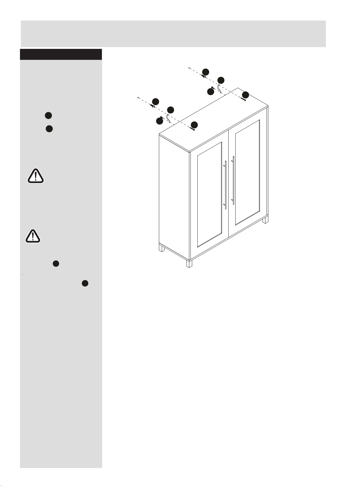
Step 8
The unit is floor
standing, but it is
recommended that the
unit is secured to the
wall.
1. Connect 2 x wall
straps to the
the unit with 2 x
screws in position
Shown
2. Move the unit into
desired position.
3. Mark the wall with a
suitable scribe the
position of the fixing
holes.
M
K
Warning:
The unit
is heavy.
Lift with care.
Warning:
Before driling,check
wall for hidden pipes
and cables.
L
M
K
L
M
K
C
C
4. Drill holes and insert 2 x
wall plugs
5. Secure the straps to the
wall using 2 x screws
Note: To hide the straps
behind the unit, drill the
holes lower than the top of
the unit
Assembly Complete
L
C
7
Page 9
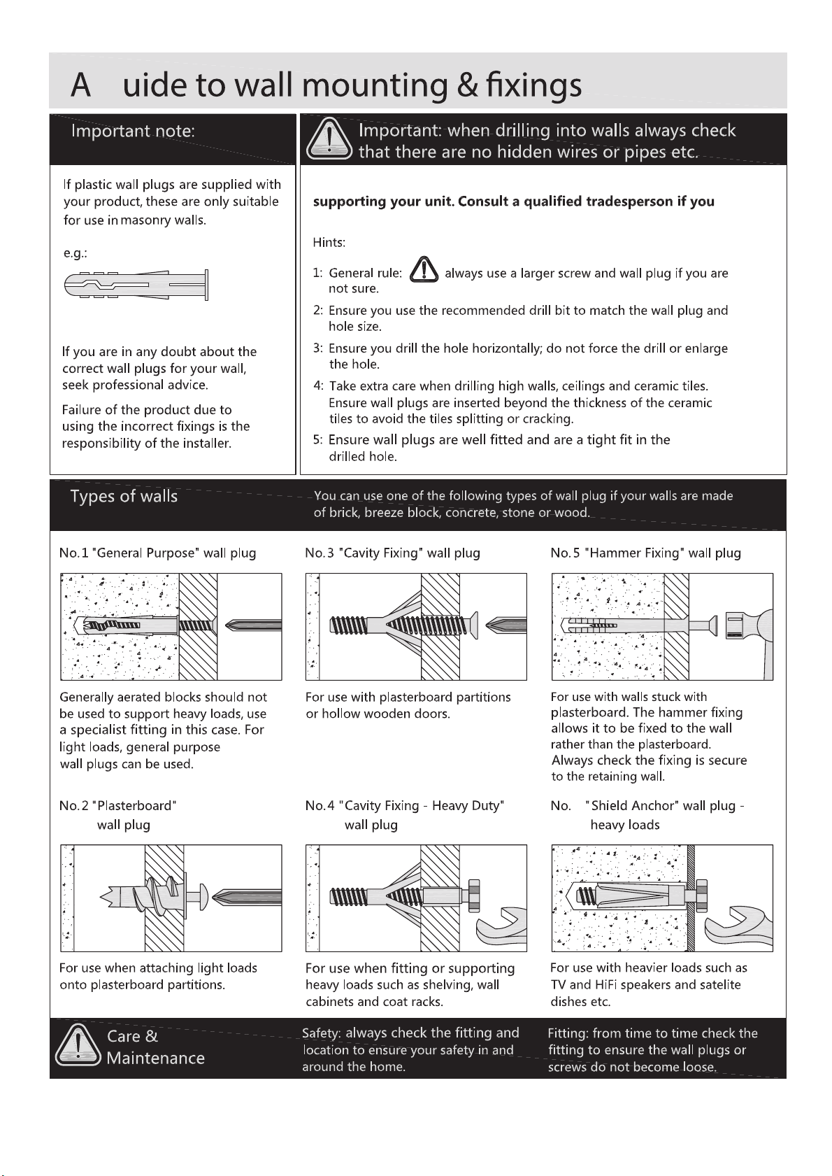
g
Make sure that the screws and wall plugs being used are suitable for
are unsure.
6
8
 Loading...