

Page 1
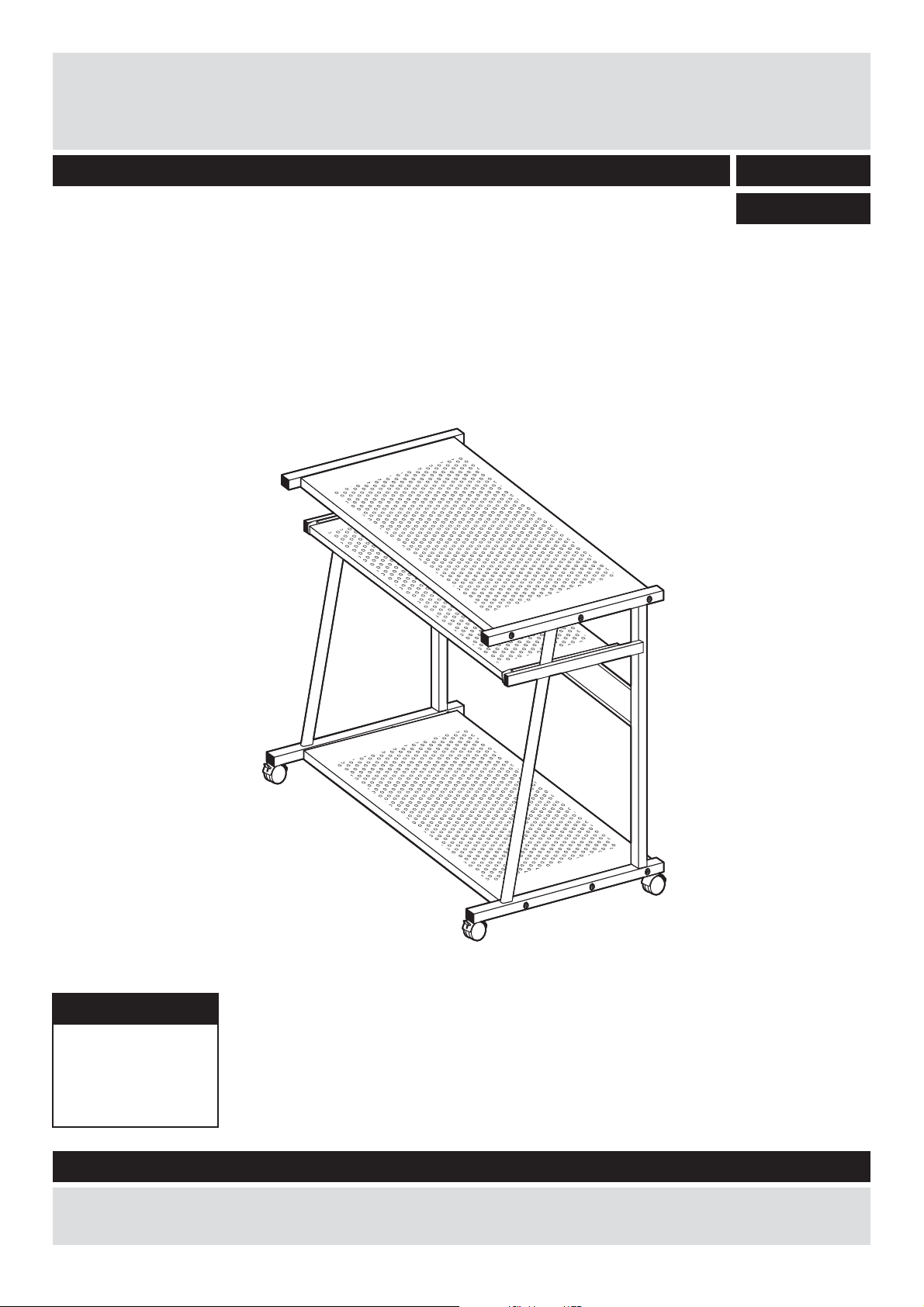
Budget PC Trolley MetalWOW -
Assembly Instructions - Please keep for future reference
617/8273
617/1328
Desk Dimensions
Width - 70cm
Depth - 55cm
Height - 76cm
Memo board Dimensions
Important - Please read these instruction fully before starting assembly
If you need help or have damaged or missing parts, call the Customer Helpline: 08456 400800
Issue 1 - 11/01/09
Page 2
Safety and Care Advice
Important - Please read these instructions fully before starting assembly
Do not stand on the product,
components and tools listed on
pages 2 and 3.
plastic bags and separate them
into their groups.
this could cause damage.
room) as possible.
as this could damage the unit.
Only use hand screwdrivers.
recommend the
use of power
drill/drivers for
inserting screws,
away from the work area, small
parts could choke if swallowed.
space to layout the parts before
starting.
surface to avoid damaging the
easier with 2 people.
Care and maintenance
and mild detergent, do not use
bleach or abrasive cleaners.
there are no loose screws on
this unit.
Keep These Instructions For Future Reference
This product complies with
BS 4875-5:2009
Argos plc
489-499 Avebury Boulevard
Central Milton Keynes
MK9 2NW
carefully and responsibly.
discarded with household
waste. Take to your local
authority waste disposal centre.
Batch No./Date of manufacture:
Note:
if required the next
page can be cut out and used
as reference throughout the
assembly. Keep this page with
these instructions for future
reference.
1
Page 3
Components - Panels
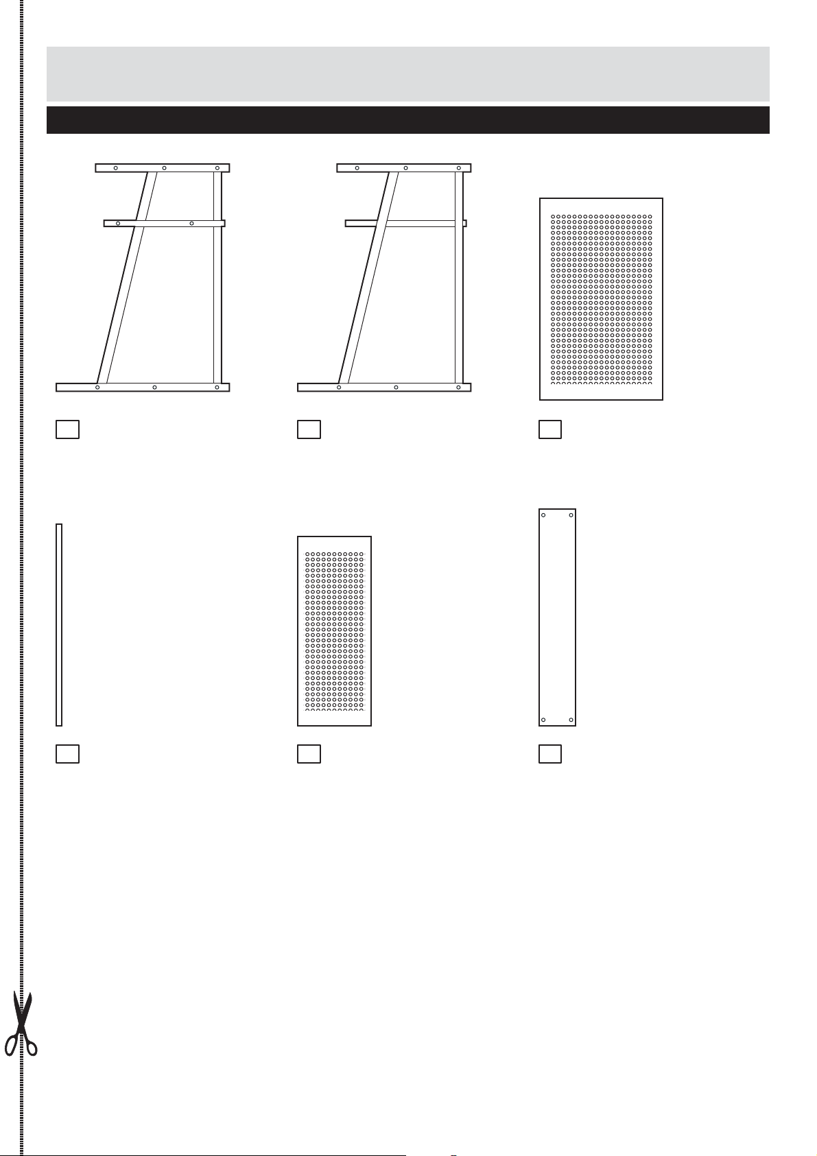
Please check you have all the panels listed below
Left hand side frame
1
(73 x 55cm)
Metal bar x6 (64.8 x 16cm)
4
Right hand side frame
2
()73 x 55cm
Keyboard shelf
5
(61 x 23.5cm)
Top and bottom shelf x2
3
(65 x 40cm)
Back panel (69.8 x 14.5cm)
6
2
Page 4
If you have damaged or missing components,
Components - Fittings
call the Customer Helpline: 08456 400800
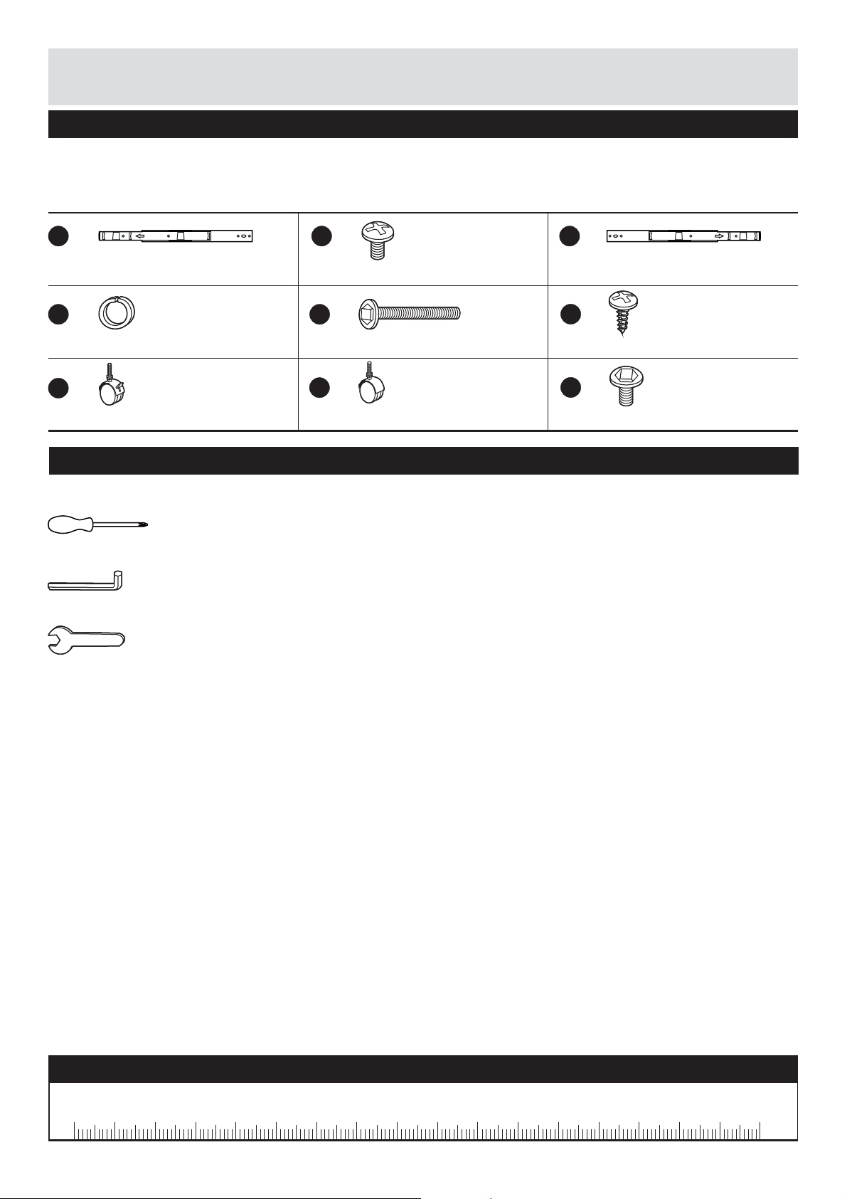
Please check you have all the fittings listed below
Note: The quantities below are the correct amount to complete the assembly. In some cases more
fittings may be supplied than are required.
A
15A01 Left side runner x 1
D
Spring washer x 16
G
Castors with brake x 2
15A01
Tools required
Screwdriver
(not included)
Allen key
(included)
Spanner
(included)
B
9mm Crosshead screw x 4
E
50mm Allen screw x 12
H
Castors without brake x2
C
15B01 Right side runner x 1
F
13mm screw x 4Crosshead
15B01
I
13mm Allen Screw x 4
Ruler - Use this ruler to help correctly identify the screws
0 5 10 15 20 25 30 35 40 45 50 55 60 65 70 75 80 85 90 95 100 110 120105 115 125 130 135 140 145 150 155 160 165 170
3
Page 5
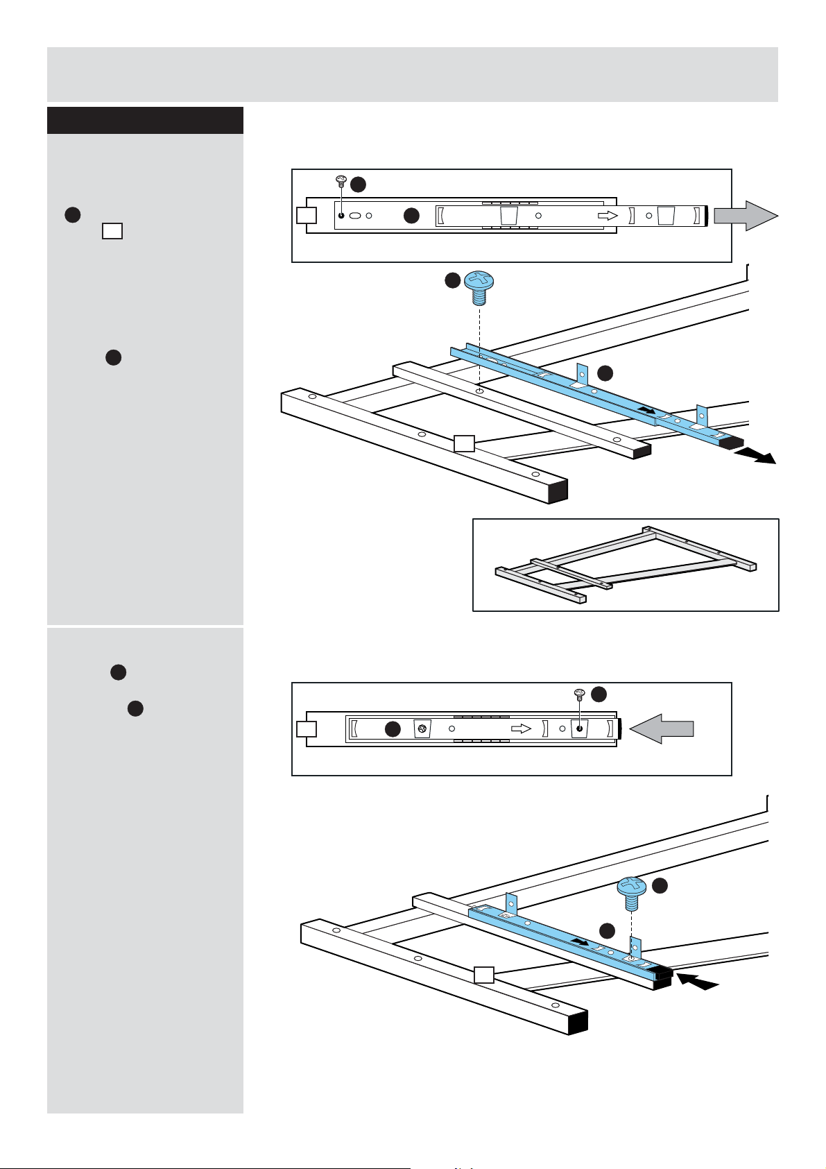
15A01
15A01
Assembly Instructions
Step 1
Attaching runner
a: Place runner
on left hand side
A
frame .
Slide top of the runner
forward.
Fix through hole as
shown by using 1 pc
screw .
1
B
15A01
a:
B
1
A
B
1
15A01
A
b Slide top of runner
:
15A01
fix as shown by using 1
pc screw .
backward and
A
B
b:
1
A
B
15A01
B
A
1
4
Page 6
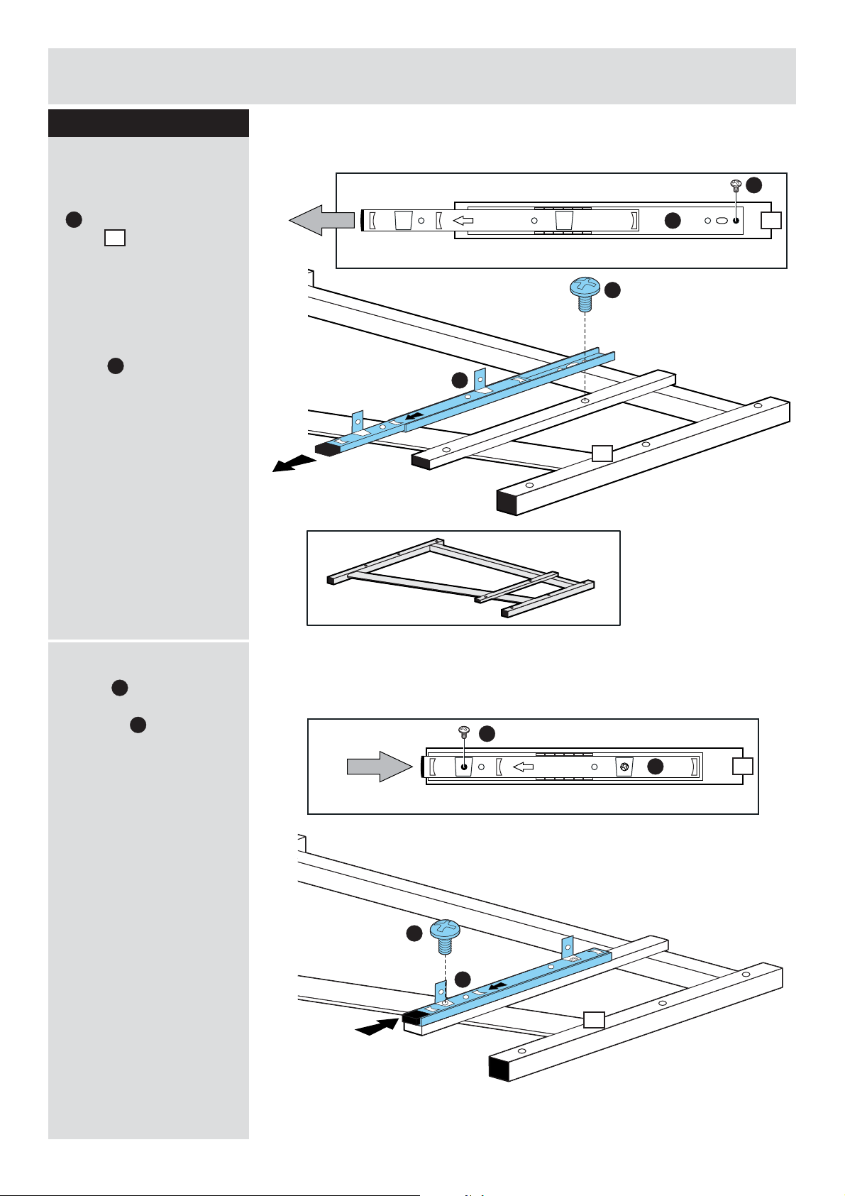
15B01
15B01
Assembly Instructions
Assembly Instructions
Step 2
Attaching runner
Place runner
a: 15B01
on right hand side
C
frame .
Slide top of the runner
forward.
Fix through hole as
shown by using 1 pc
screw .
2
B
a:
B
15B01
B
C
2
C
2
b Slide top of runner
:
15B01
fix as shown by using 1
pc screw .
backward and
C
B
b:
B
15B01
B
C
2
C
2
5
Page 7
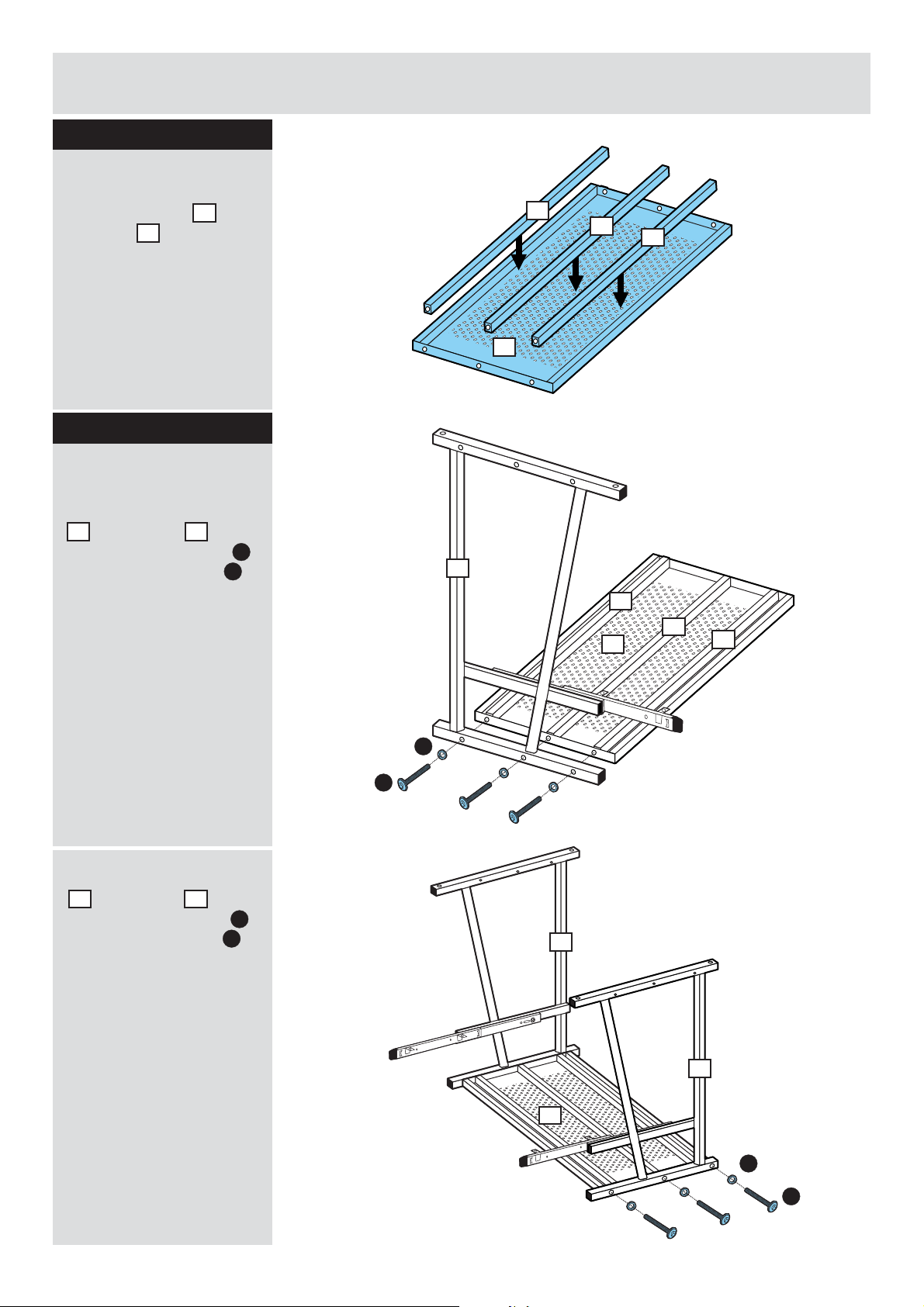
Assembly Instructions
Step 3
Attaching metal bar
Fix 3 metal bars to
top shelf .
3
4
Step 4
Attaching top shelf
a: Attach metal frame
to top shelf by
1
using 3 pcs of screw
and spring washers .
3
E
D
a:
4
4
3
1
4
4
4
3
4
b: Attach metal frame
to top shelf by
2
using 3 pcs of screw
and spring washers .
3
E
D
D
E
b:
1
2
3
D
E
6
Page 8
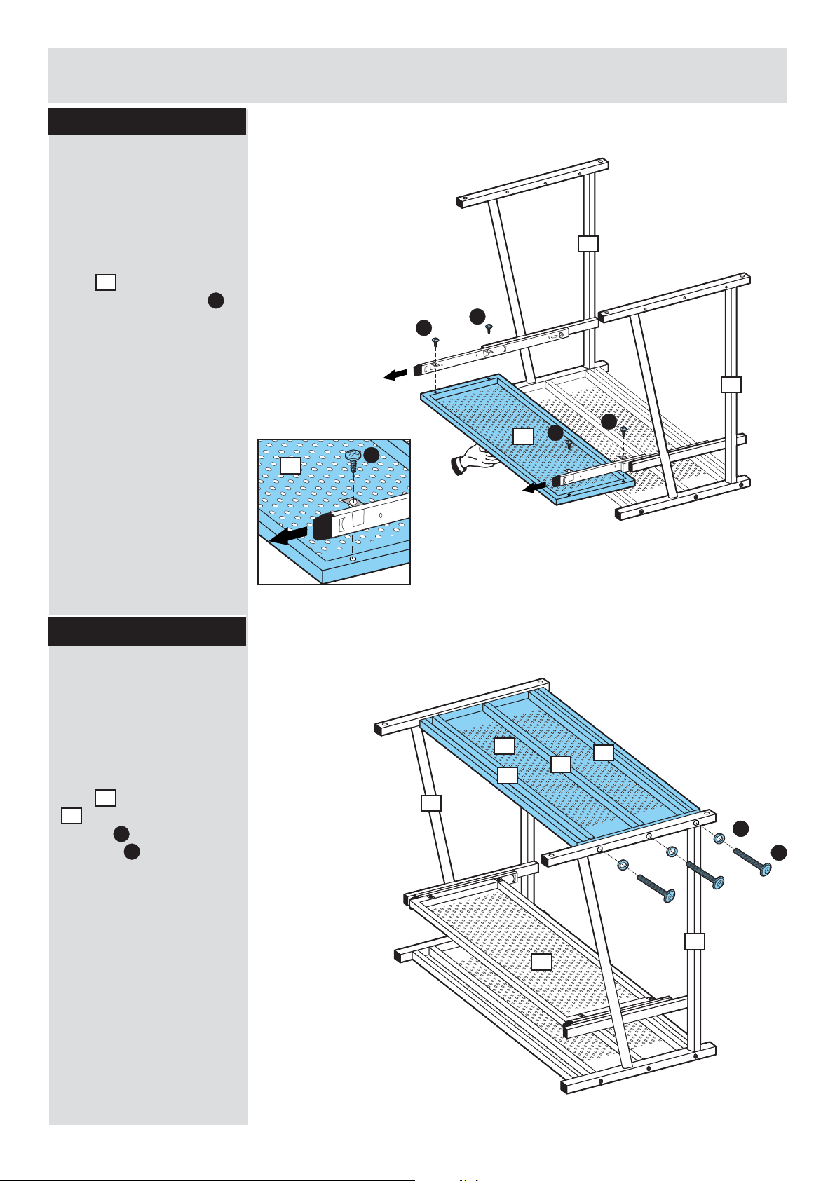
Assembly Instructions
Step 5
Attaching keyboard
shelf
Two people are required
here.
Attach the keyboard
shelf to the unit by
using 4 pcs of screw .
5
F
1
F
F
2
Step 6
Attaching bottom
shelf
Two people are required
here.
Attach the bottom
a:
shelf to metal frame
screws and spring
washers .
3
by using 3 pcs of
2
E
D
F
5
5
F
F
a:
3
4
1
4
4
C
D
E
2
5
7
Page 9
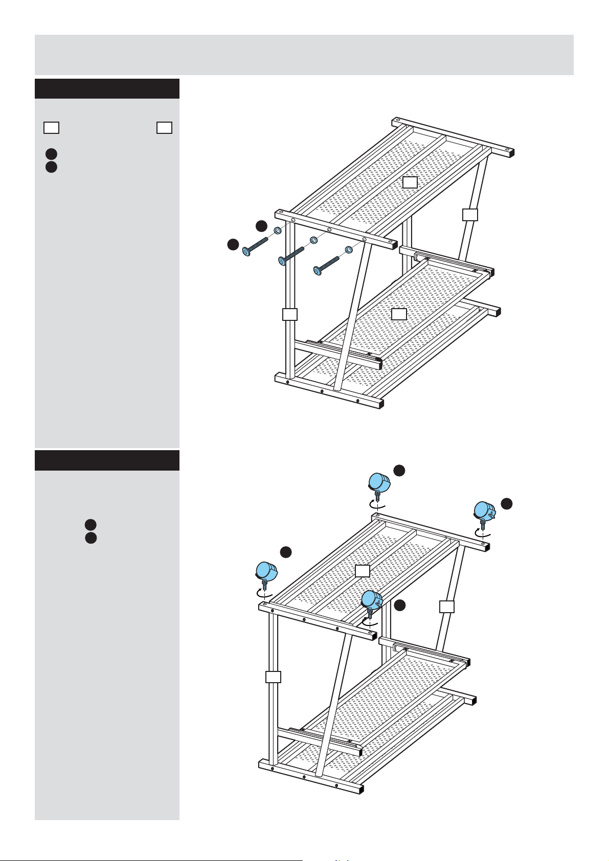
Assembly Instructions
Step 6 - continued
b: Fix the bottom shelf
to the metal frame
3
by using 3 pcs of screws
and spring washers
E
.
D
1
b:
D
E
3
2
Step 7
Attaching castors
Fix 2 pcs of brake
castors and 2 pcs of
castors to the unit.
G
H
1
H
3
4
H
G
G
2
1
8
Page 10
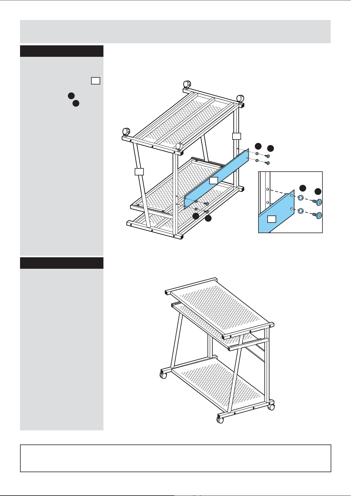
Assembly Instructions
Step 8
Attaching back panel
Attach the back panel
to the unit by using 4
pcs of screws and
spring washers .
I
D
6
1
D
I
2
6
D
I
D
I
6
Step 9
Assembly is
complete.
If you need help or have damaged or missing parts, call the Customer Helpline:
9
08456 400800
 Loading...