

Page 1
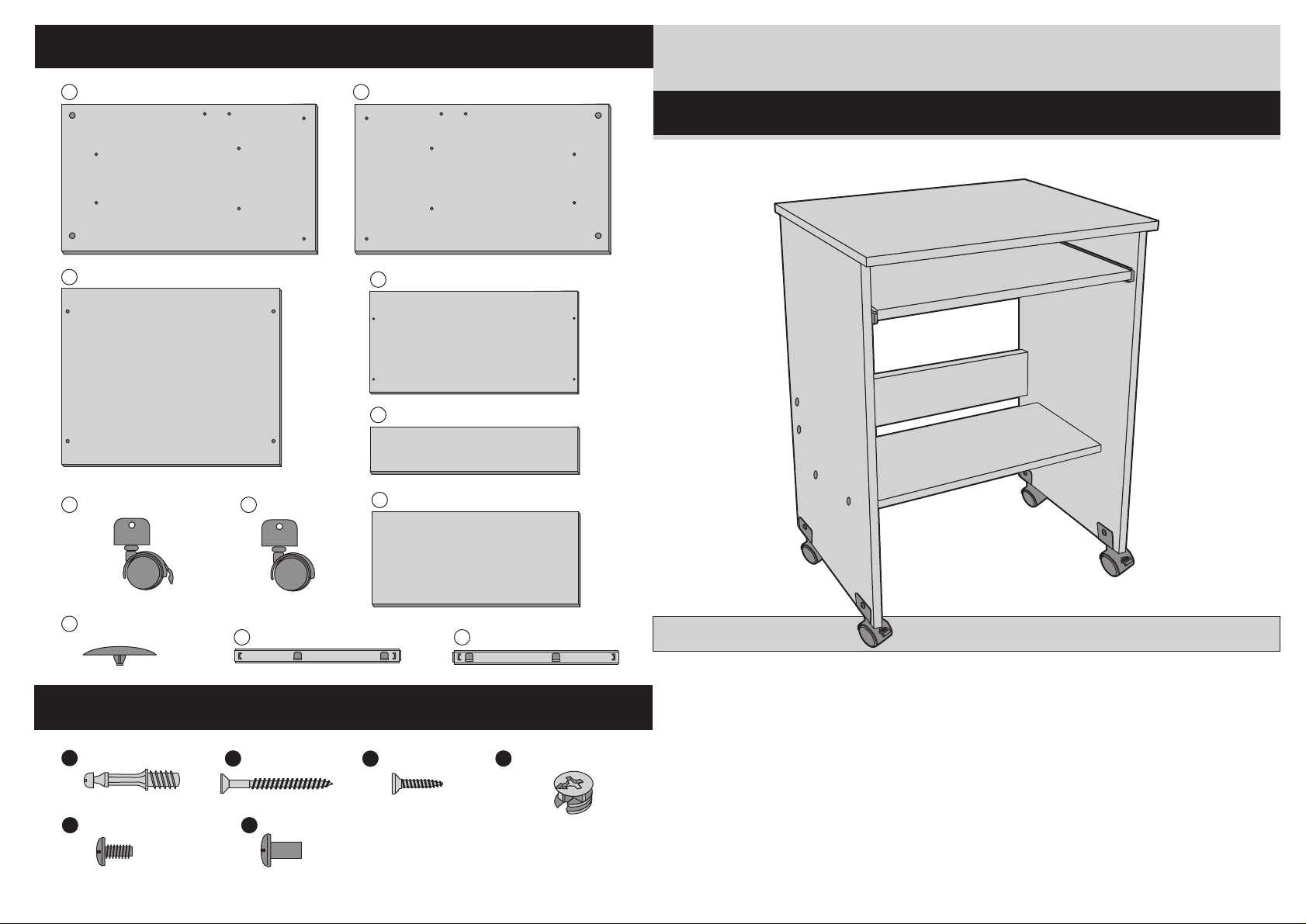
Components
A
1 x Left Side Panel 1 x Right Side Panel
1 x Table Top
C
B
1 x Keyboard Drawer
D
1 x Support
E
Functional Simple Workstation
Simple Assembly Instructions - Please keep for future reference
G
2 x Front Castor
8 x Plastic Plug
J
Fittings
A
4 x Locking Pin
4 x Screw
E
2 x Castor
H
K
8 x Screw
B
F
4 x Nut
1 x Shelf
F
8 x Screw
C
1 x Left Track1 x Right Track
L
D
4 x Locking Nut
8-06
IMPORTANT
1. Read these instructions carefully and
familiarise yourself with the procedure
before assembling the unit.
2. Check that you have all the component
parts following the list on the back
cover and familiarise yourself with
each part before proceeding.
3. Take all the fittings out of the plastic bag
and separate them into their groups.
4. Ensure you have enough space to lay out
all the parts before assembly.
5. To avoid scratching it is recommended
that you assemble the unit on a soft
level surface.
Page 2
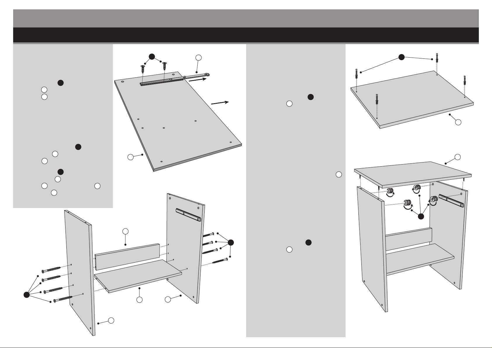
Assembly Instructions
Assembly Instructions
Stage 2 – Fitting the Table TopStage 1 – Fitting the Side Panels
NOTE: It would be useful to ask
someone to help you at this
stage.
1. Use Screws C to fix the Right
Track K on the Right Side
Panel B.
See fig. 1.
NOTE: The front part of the Track
should be close to the edge of
the panel.
2. Follow the same method as in
fig. 1 using Screws C to fix the
Left Track L onto the Left Side
Panel A.
3. Use Screws B to fix the Left
Side Panel A and Right Side
Panel B onto the Support E
and Shelf F.
See fig. 2.
C
Front
B
K
Front
fig. 1
NOTE: It would be useful to ask
someone to help you at this
stage.
1. Screw Locking Pin A into the
Table Top C.
See fig. 3.
2. Carefully locate the Table Top C
on top of the unit.
See fig. 4.
A
fig. 3
D
C
C
E
B
B
fig. 2
A
F
B
3. Use Locking Nuts D to fix the
Table Top C onto the unit.
See fig. 4.
fig. 4
Page 3
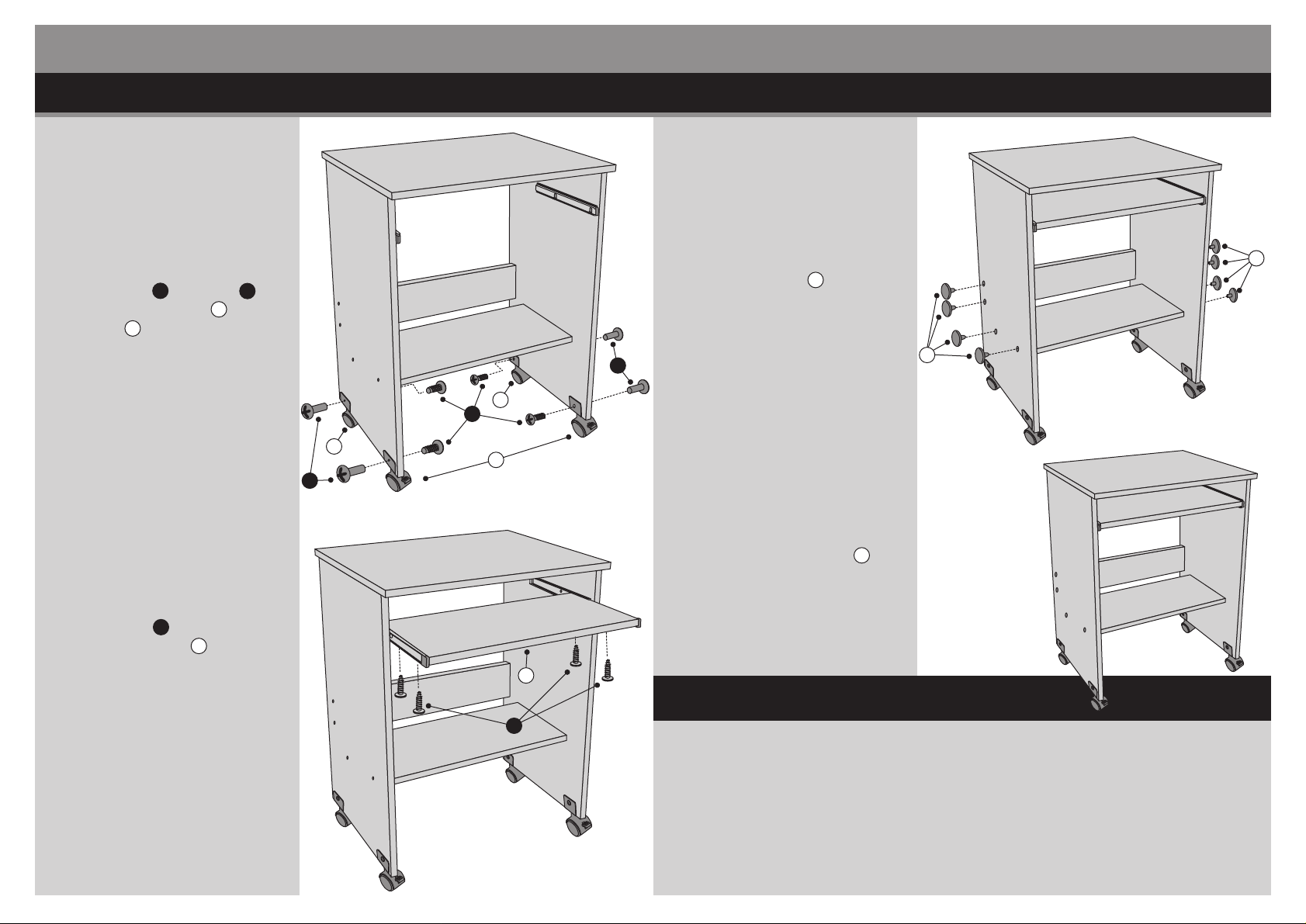
Assembly Instructions
Assembly Instructions
Stage 4 – Finishing the UnitStage 3 – Fitting the Castors
NOTE: It would be useful to ask
someone to help you at this
stage.
1. Use Screws E and Nuts F to
fix the Front Castors G and
Castors H onto the unit.
See fig. 5.
2. Use Screws C to fix the
Keyboard Drawer D onto the
Tracks.
See fig. 6.
NOTE: It would be useful to ask
someone to help you at this
stage.
fig. 5
J
1. Use Plastic Plugs J to cover the
Screw Heads.
See fig. 7.
F
H
E
H
G
F
D
2. Carefully place the unit in the
desired location.
See fig. 8.
NOTE: The Front Castors G
feature a locking arm. We
recommend you lock the
castors when you have finally
positioned the unit in place.
J
fig. 7
fig. 8
Care and Maintenance
C
fig. 6
Safety
To avoid any risk of suffocation to animals or children dispose of the plastic
bags immediately.
Cleaning
As with all surfaces clean with a damp cloth and mild detergent, do not use bleach
or abrasive products.
Fitting
From time to time please ensure there are no loose screws on the product.
Page 4

Page 5

Page 6

Page 7

Page 8

Page 9

Page 10

 Loading...