

Page 1
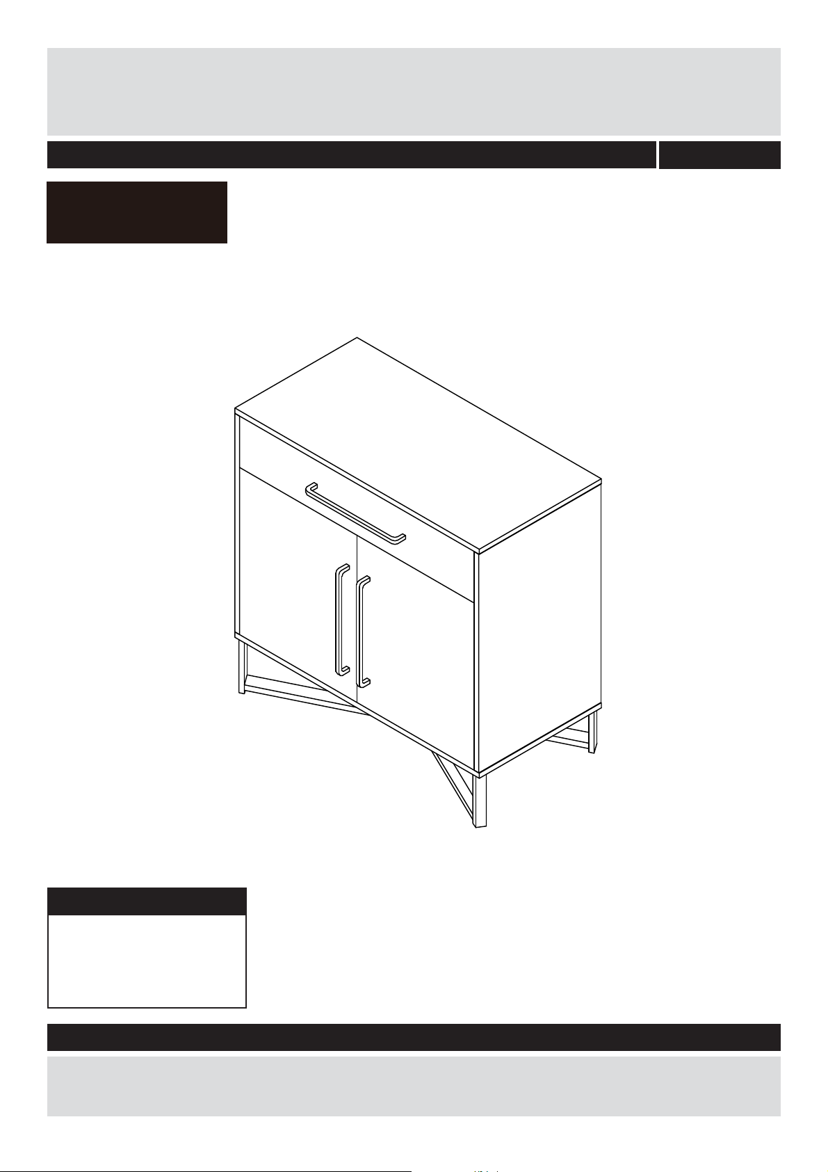
FITZ SIDEBOARD
Assembly Instructions
hygena
- Please keep for future reference
614/9305
DIMENSIONS
Width:
Depth:
Height:
Important
If you need help or have damaged or missing parts, call the Argos Aftersales
Helpline: 0345 640 0800
80 cm
40 cm
80 cm
– Please read these instructions fully before starting assembly
Issue 1-22/09/2016
Page 2
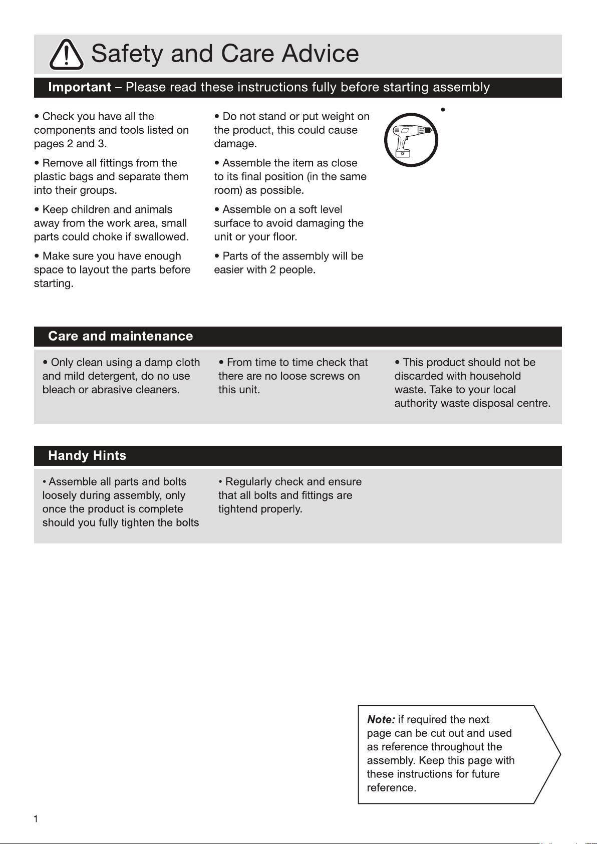
To reduce the likelihood
of damaging your product,
please ensure that your
power drill is set on a low
torque setting.
Page 3
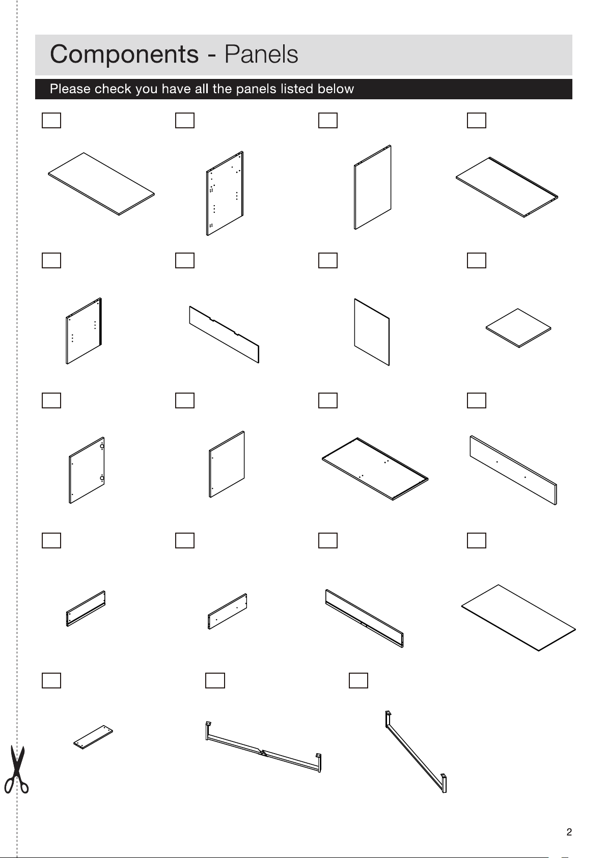
Top board
1
( 80 x 40 CM) ( 62 x 40 CM) (62 x 40 CM) (76.9 x 38.4 CM)
Side board
2
Side board
3
4
Divider
Divider
5
(45 x 38.4 CM) (77.9 x 16.5 CM) (38.7 x 46 CM) (37.5 x 36 CM)
Door
9
(45.2 x 38 CM) (45.2 x 38 CM) (80 x 40 CM) (76.4 x 15.6 CM)
Drawer side
13
(35 x 12 CM) (35 x 12 CM) (72.2 x 12 CM) (34.8 x 73.2 CM)
Back board
6
Door
10
Drawer side
14
Back board x 2
7
Bottom board
11
Drawer back
15
Shelf x 2
8
Drawer front
12
Drawer bottom
16
Drawer bottom support
17
(33.8 x 9 CM) (86.5 x 14.5 CM) (86.5 x 14.5 CM)
18
Leg
19
Leg
Page 4
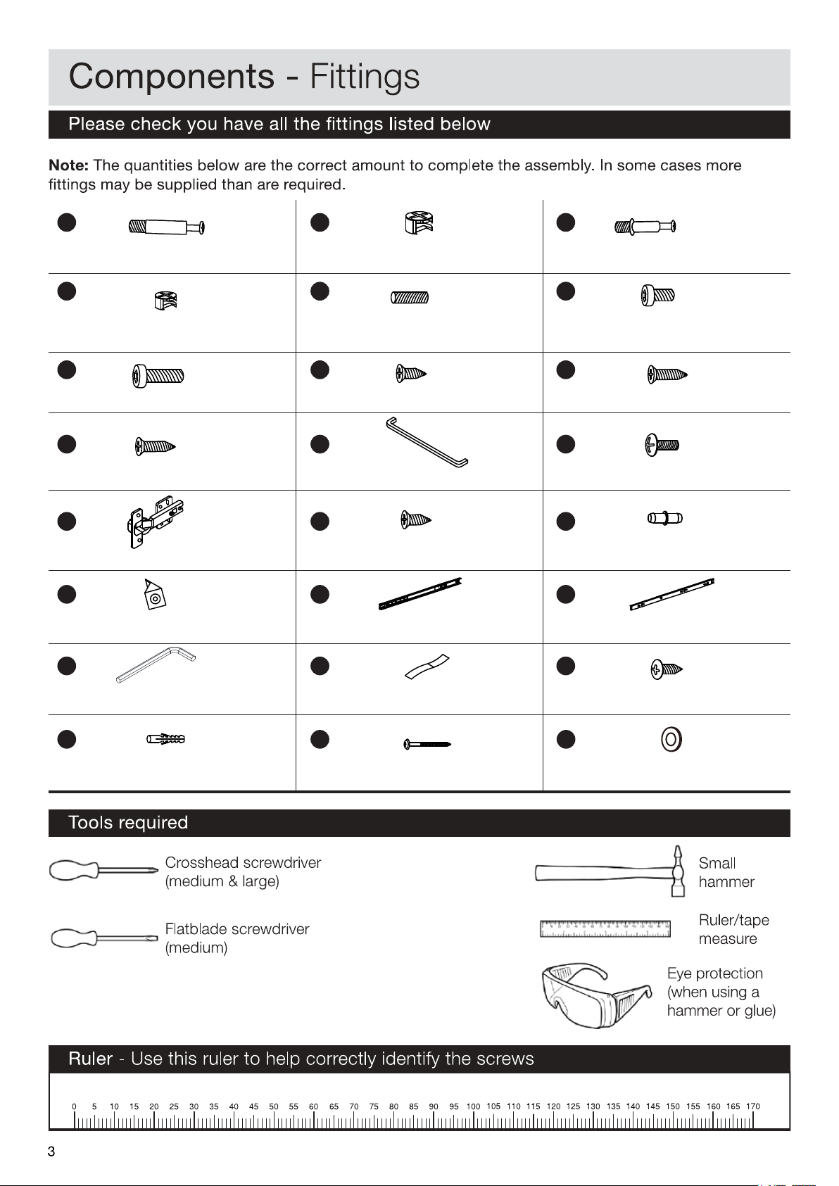
B
CA
CAMLOCK SCREW (35MM )X 12 CAMLOCK NUT( Ø15MM )X 12
E
CAMLOCK NUT( Ø12MM) X 8 WOODEN DOWEL( Ø8 X 30MM )
X 18
H
BOLT ( Ø6 X 45MM ) X 4 SCREW ( Ø3.5 X 12MM ) X 8
K
SCREW ( Ø3.5 X 30MM ) X 4 HANDLE (294MM) X 3
N
HINGE (80 X 62MM) X 4 SCREW ( Ø4 X 16MM ) X 24
Q
BACK SUPPORT (15 X 10MM) X 8 RUNNER (350MM) X 2
CAMLOCK SCREW (25MM )X 8
FD
BOLT ( Ø6 X 12MM ) X 5
IG
SCREW ( Ø3.5 X 16MM ) X 8
LJ
SCREW ( Ø4 X 20MM ) X 6
OM
PIVOT PIN (16MM) X 8
RP
RUNNER ( 350MM) X 2
S
S
ALLEN KEY (68 X 25MM) X 1
T
FABRIC STRIP (147 X 25MM ) X 2
W
WALL ANCHOR(Ø5 X 35MM) X 2 SCREW ( Ø5 X 35MM ) X 2
U
SCREW ( Ø4 X 12MM ) X 4
XV
WASHER ( Ø5 X 1MM ) X 2
Page 5
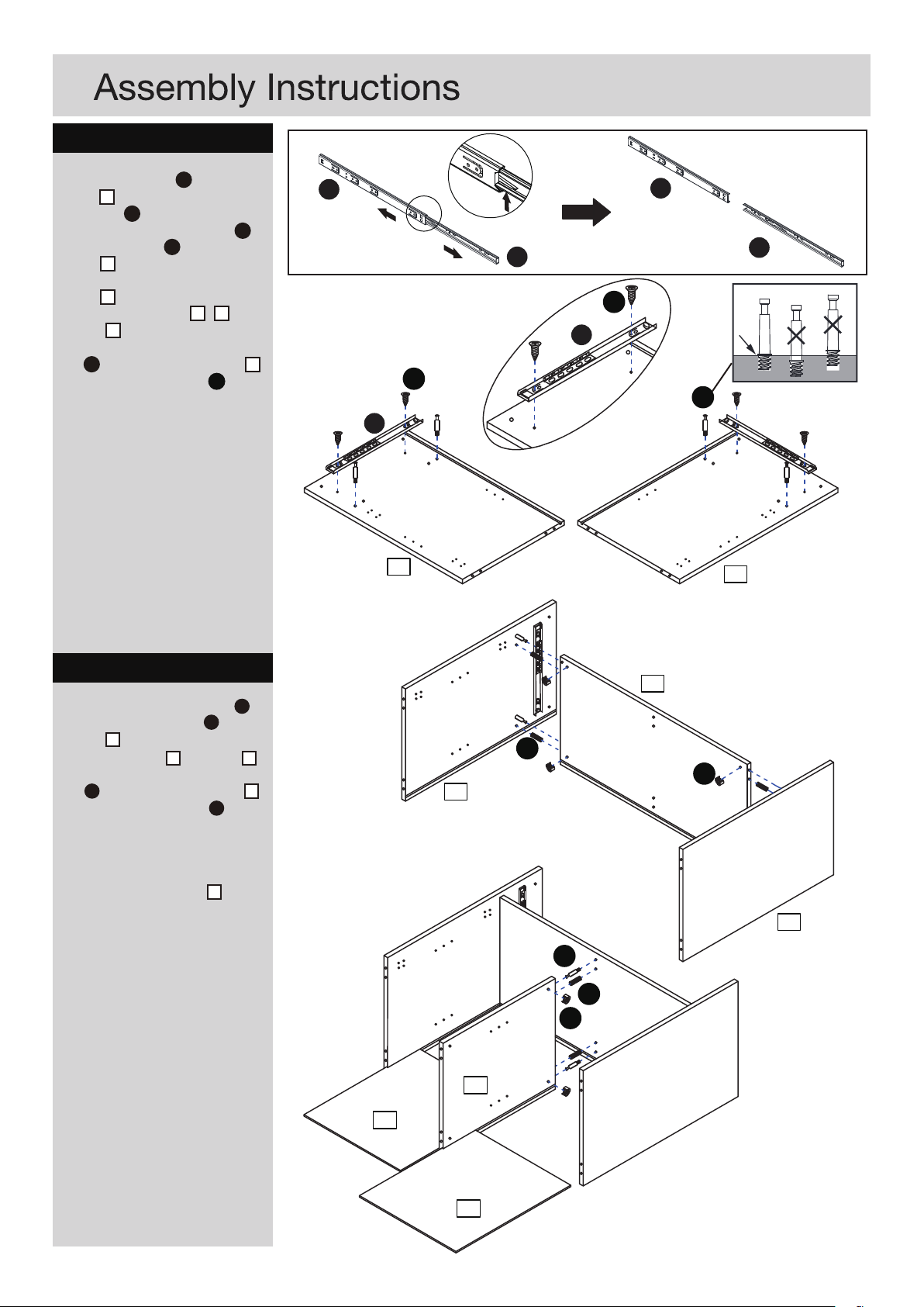
Step 1
a: Position runner Q on side
board 2 and fix into place using
2 x screw H .
b: Insert 2 x camlock screw A , 2
x wooden dowel E into side
board 2 .
c: Repeat the above for side
board 3 .
d: Attach side board 2 & 3 to
divider 4 .
Align the arrow on 2 x camlock
nut B with the edge of divider 4 .
Rotate all camlock nuts B
clockwise for about 1/4 or 1/2 a
turn or until the bolts “connects”
with the screw and is secure.
a:
Q
Q
QQ
R
Q
R
H
QQ
H
A
2
3
Step 2
a: A
Insert 2 x camlock screw
and 2 x wooden dowel
divider 4 .
b: Attach divider 5 to divider 4 .
Align the arrow on 2 x camlock
nut B with the edge of divider 5 .
Rotate all camlock nuts B
clockwise for about 1/4 or 1/2 a
turn or until the bolts “connects”
with the screw and is secure.
c:
Slide 2 x back board 7 into
the assembled section
E on
b:
E
4
B
2
abc:
A
E
B
3
5
7
7
4
Page 6
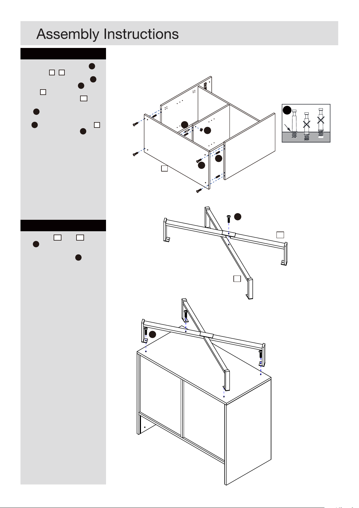
Step 3
a: Insert 2 x wooden dowel E on
side board 2 & 3
b: Insert 2 x camlock screw A
and 2 x wooden dowel E on
divider 5
c: Attach bottom board 11 to the
assembled section using 4 x
bolt G .
Align the arrow on 2 x camlock
nut B with the edge of divider 5 .
Rotate all camlock nuts B
clockwise for about 1/4 or 1/2 a
turn or until the bolts “connects”
with the screw and is secure.
Step 4
a:
Attach leg 18 to leg 19 using
bolt F .
b:
Attach legs to the assembled
section using 4 x bolt .
F
a:
11
A
A
B
E
G
F
18
b:
19
F
45
Page 7
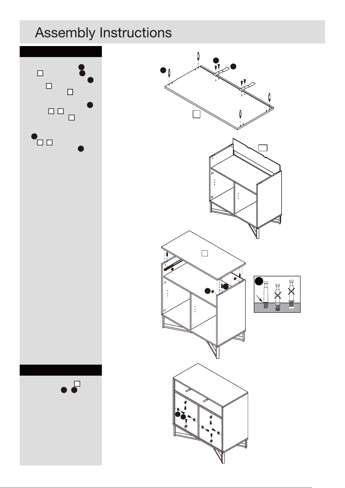
Step 5
a: Attach 2 x fabric strip T to top
board 1 using 2 x screw U .
b: Insert 4 x camlock screw A on
top board 1 .
Slide back board 6 into the
c:
assembled section.
d: Insert 4 x wooden dowel E on
side board 2 & 3
e: Attach top board 1 to the
assembled section.
Align the arrow on 2 x camlock
nut B with the edge of side
board 2 & 3 .
Rotate all camlock nuts B
clockwise for about 1/4 or 1/2 a
turn or until the bolts “connects”
with the screw and is secure.
a:
b:
c:
U
A
T
1
6
Step 6
Secure the back board 7 using 8
x wall support kit I & P .
d:
e:
1
A
B
P
I
E
65
Page 8
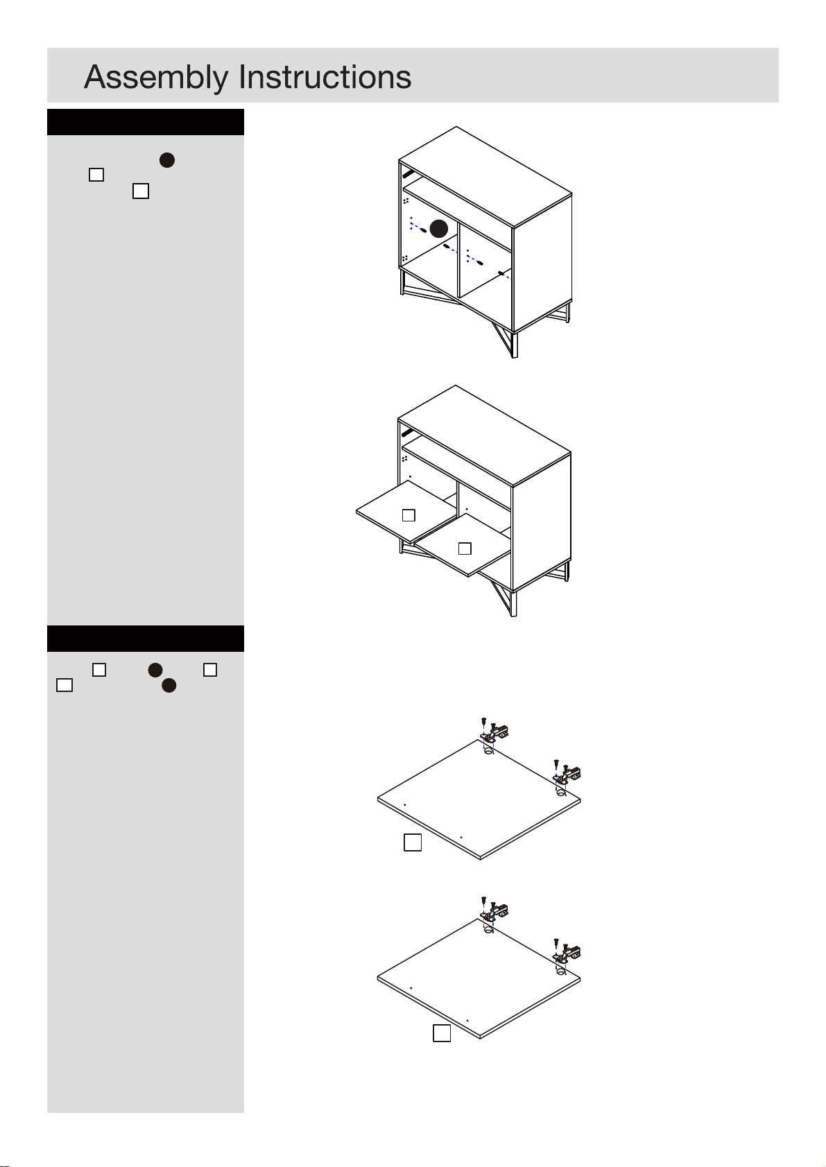
Step 7
Insert 2 x pivot pin
board 2 .
Put 2 x shelf 8 into the
assembled section.
O into side
O
8
8
Step 8
Attach 2 x hinge M to door 9 &
10 using 4 x screw N for each
door.
N
M
9
10
Page 9
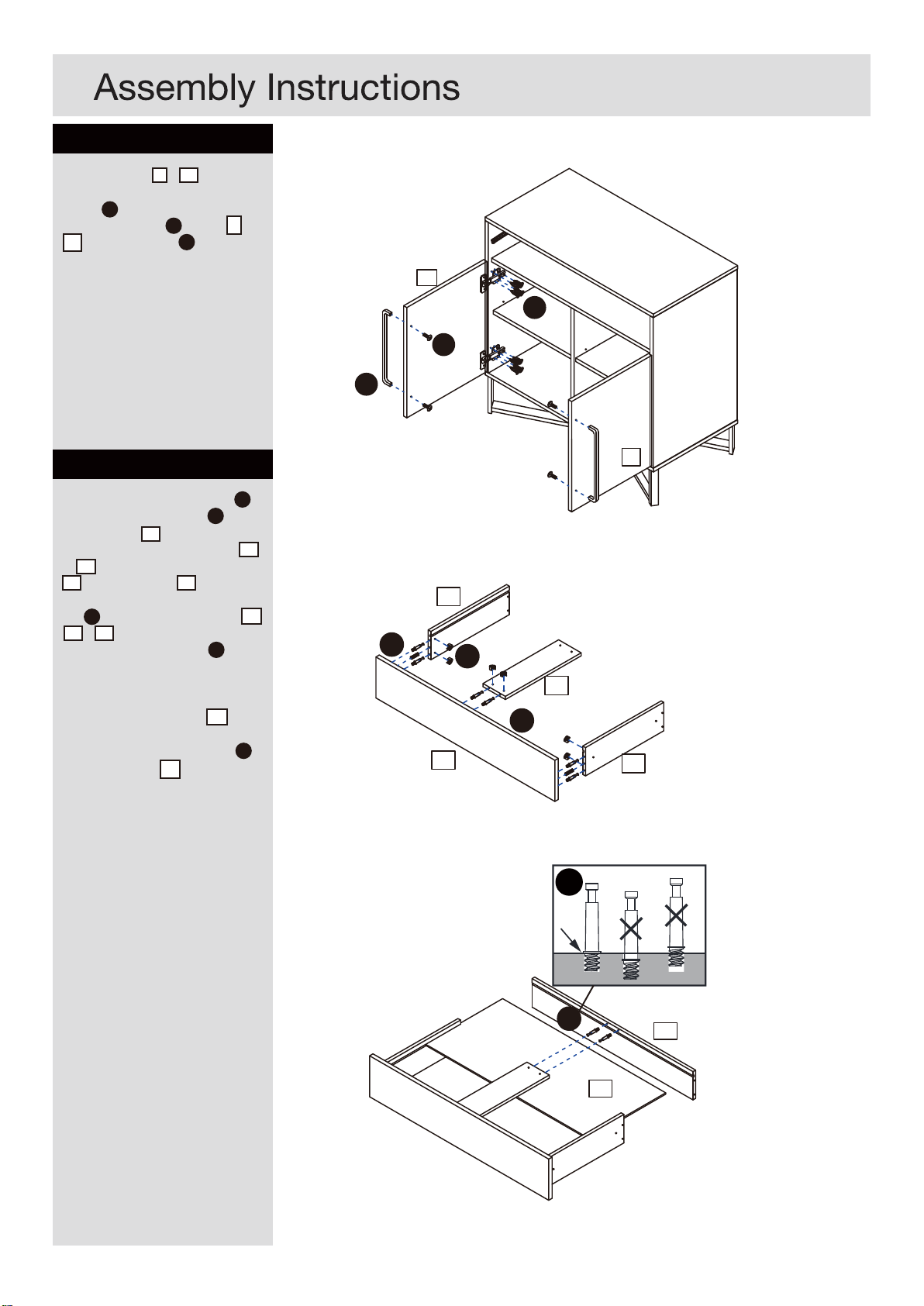
Step 9
a: Attach door 9 & 10 to the
assembled section using 8 x
screw N for each.
b: Attach handle K
10 using 2 x screw
to door 9 &
L for each.
a:
b:
9
N
L
K
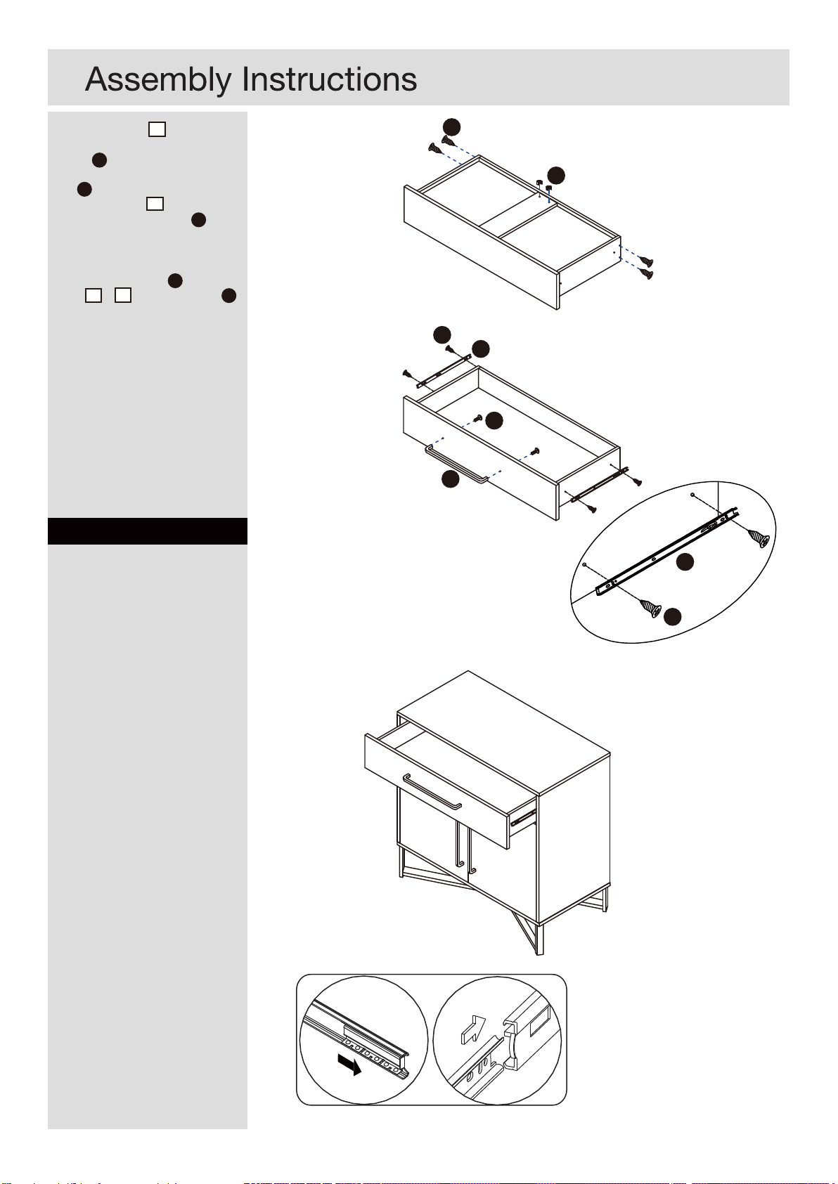
Step 10
a: Insert 6 x camlock screw C
and 2 x wooden dowel E on
drawer front 12 .
b: Attach drawer side board 13
& 14 and drawer bottom support
17 to drawer front 12 .
Align the arrow on 2 x camlock
with the edge of board 13 ,
nut D
14 & 17 .
Rotate all camlock nuts D
clockwise for about 1/4 or 1/2 a
turn or until the bolts “connects”
with the screw and is secure.
c: Slide drawer bottom 16 into
the assembled section.
d: Insert 2 x camlock screw C
on drawer front 15 .
a:
b:
E
12
10
14
D
17
C
13
C
c:
d:
C
15
16
77
Page 10
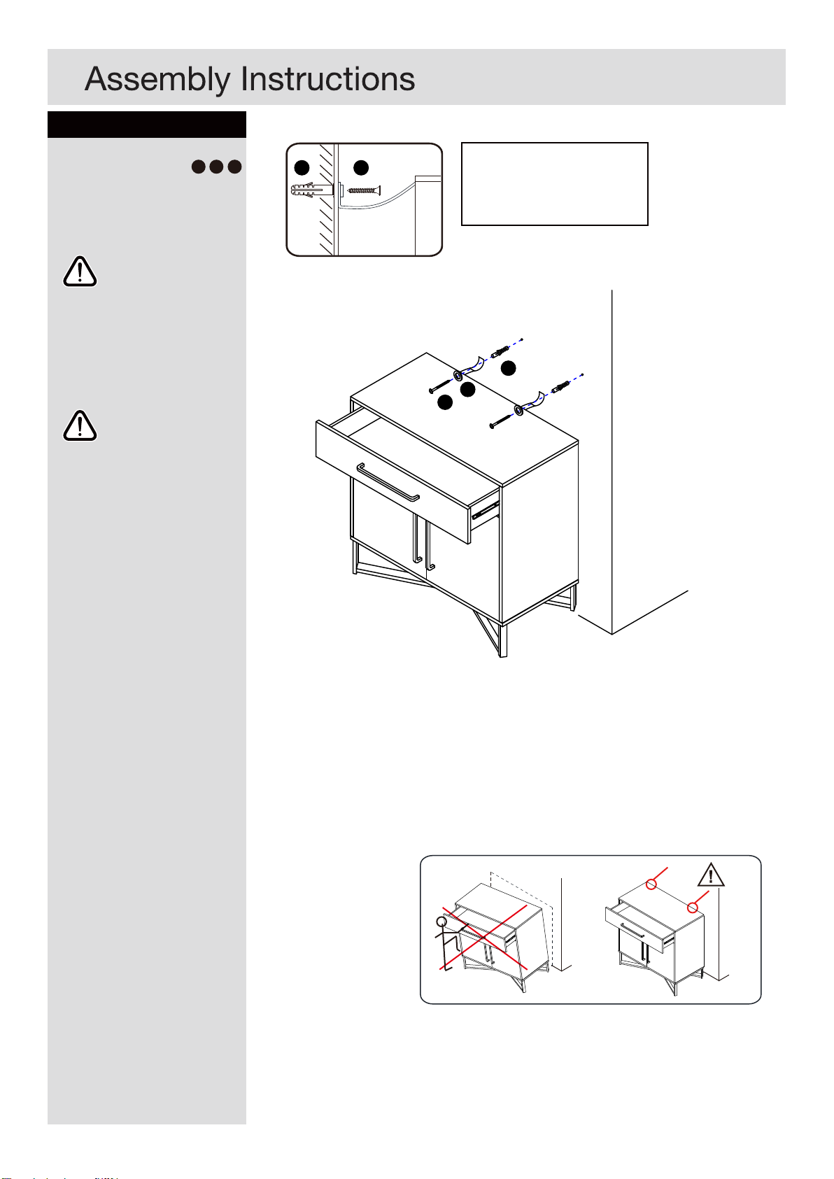
e: Attach board 15 to the
assembled section using 4 x
screw J .
Align the arrow on 2 x camlock
nut D with the edge of drawer
bottom support 17 .
Rotate all camlock nuts D
clockwise for about 1/4 or 1/2 a
turn or until the bolts “connects”
with the screw and is secure.
f: Attach 2 x runner R to drawer
side 13 & 14 using 2 x screw H
for each.
J
e:
D
Step 11
Please insert the drawer into the
assembled section.
f:
H
R
L
K
7
R
H
8
Page 11
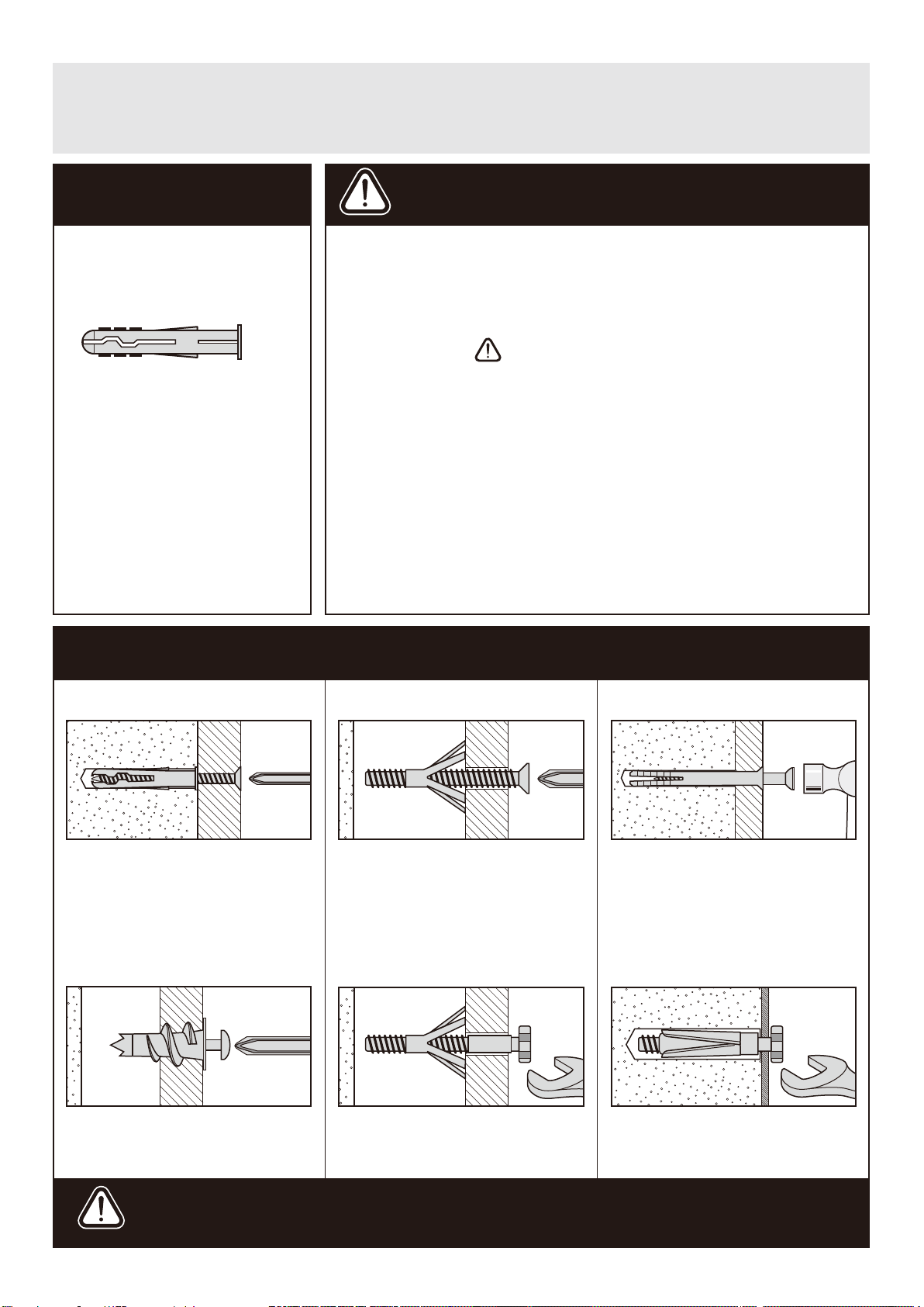
Step 12
a:
Fixing to wall
Attach the wall strap kit V , X , W
as shown on the drawing.
Warning:
In order to prevent
overturning this
product must be
used with the wall
attachment advice
provided.
Warning:
Before drilling, check
wall for hidden pipes
and cables.
V W
Note: Wall plugs supplied are
for solid wall only.
The correct type of fixing must
be used for your wall, seek
professional advice if in doubt
V
X
W
Assembly is complete.
5
9
Page 12
A Guide to - Wall Mounting & Fixings
Important note:
If plastic wall plugs
are supplied with your
product:
- these are only suitable for
use in masonry walls.
If you are in any doubt about
the correct wall plugs for
your wall, seek professional
advice.
Failure of the product due to
using incorrect fxings is the
responsibility of the installer.
Important: When drilling into walls always
check that there are no hidden wires or pipes etc.
Make sure that the screws and wall plugs being used
are suitable for supporting your unit. Consult a qualifed
tradesperson if you are unsure.
Hints:
1: General rule: Always use a larger screw and wall plug
if you are not sure.
2: Ensure you use the recommended drill bit to match the wall
plug and hole size.
3: Ensure you drill the hole horizontally, do not force the drill or
enlarge the hole.
4: Take extra car e when drilling high walls, ceilings and ceramic
tiles. Ensure wall plugs are inserted beyond the thickness of
the ceramic tiles to avoid the tiles splitting or cracking.
5: Ensure wall plugs are well ftted and are a tight ft in the
drilled hole.
Types of walls
No.1 “General Purpose” wall plug
Generally aerated blocks should not
be used to support heavy loads, use
a specialist ftting in this case. For light
loads, general purpose wall plugs can
be used.
No.2 “Plasterboard” wall plug
You can use one of the following types of wall plug if your walls are made
of brick, breeze block, concrete,
No.3 “Cavity Fixing” wall plug
For use with plasterboard partitions or
hollow wooden doors.
No.4 “Cavity Fixing-Heavy Duty”
wall plug
stone or wood.
No.5 “Hammer Fixing” wall plug
For use with walls stuck with
plasterboard. The hammer fxing allows
it to be fxed to the wall rather than the
plasterboard. Always check the fxing
is secure to the retaining wall.
No.6 “Shield Anchor” wall plug
Heavy loads
For use when attaching light loads on
to plasterboard partitions.
Care &
Maintenance
For use when ftting or supporting
heavy loads such as shelving, wall
cabinets and coat racks.
Safety: Always check the ftting
and location to ensure your safety
in and around the home.
For use with heavier loads such as TV
& HiFi speakers and satelite dishes etc.
Fitting: From time to time check
the ftting to ensure the wall plugs
or screws do not become loose.
 Loading...