

Page 1
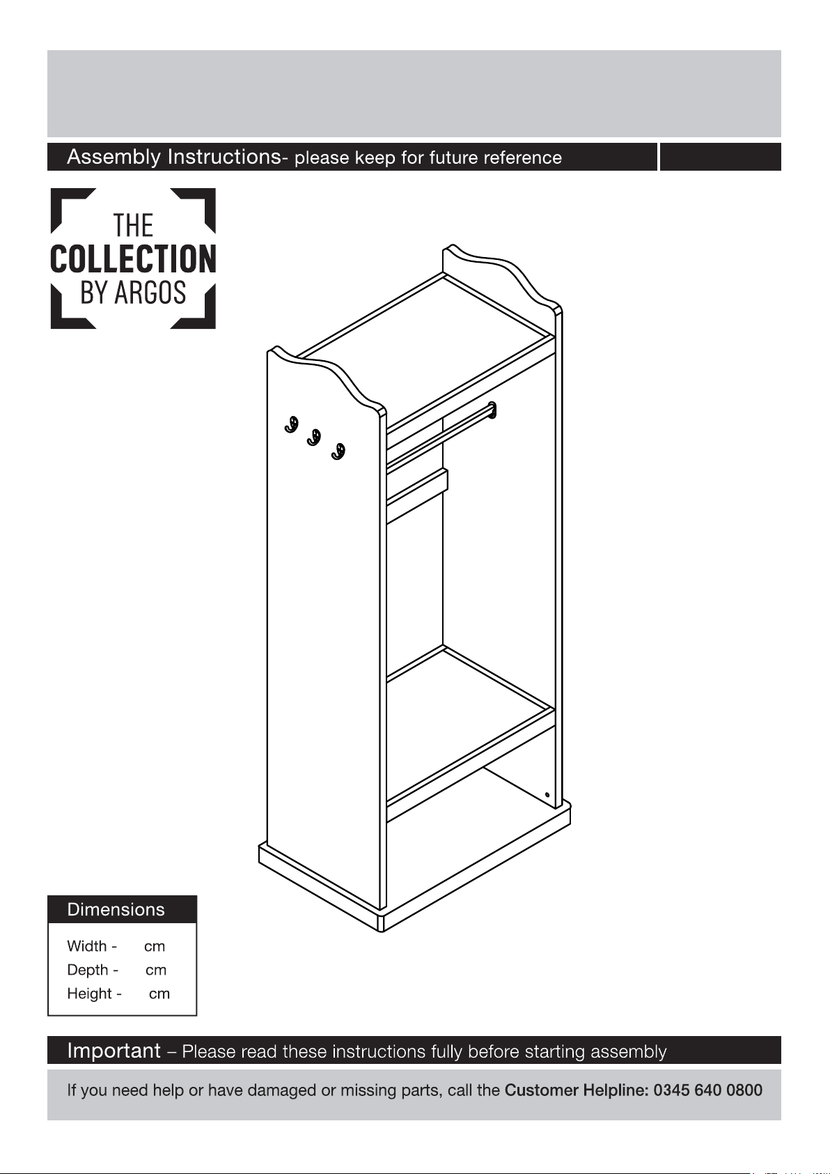
Mirrored Clothes Rail
614/7888
72
46
175
Issue 1 - 26/09/16
Page 2
Safety and Care Advice
Important – Please read these instructions fully before starting assembly
components and tools listed on
pages 3 and 4..
plastic bags and separate them
into their groups.
space to layout the parts before
starting.
Care and maintenance
bleach or abrasive cleaners.
y do not stand
this could cause damage.
Assemble the item as close
room) as possible.
Assemble on a soft level
surface to avoid damaging the
easier with 2 people.
there are no loose screws on
this unit.
We do not
recommend the use
of power drill/drivers
as this could damage
screwdrivers
This product should not be
discarded with household waste.
T
waste disposal centre.
Handy Hints
Assemble all parts and bolts
loosely during assembly
once the product is complete
should you fully tighten the bolts
and ensure
tightend properly.
1
Page 3
If you have damaged or missing components, call the
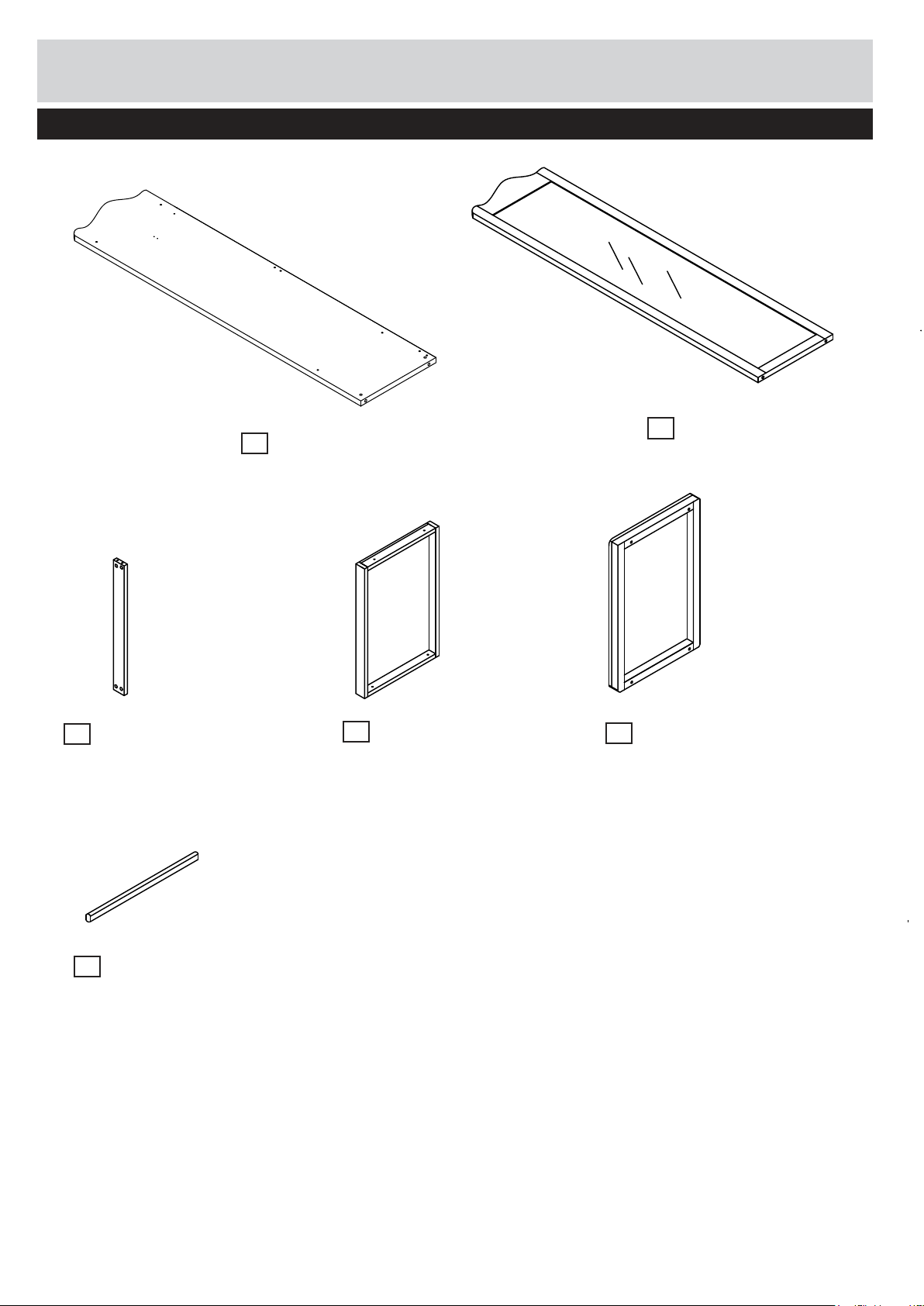
Components - Panels
Customer Helpline:
Please check you have all the panels listed below
Side Panel x 1
1
(169.8(w)cm*42(d)cm)
0345 640 0800
2
Mirrored Side Panelx 1
(169.8(w)cm*42(d)cm)
Cross Plinth x 2
3
(63(w)cm*6(d)cm)
Rail x 1
6
(61.8(w)cm*3(d)cm)
Top/Shelf Panel x 2
4
(63(w)cm*41.8(d)cm)
Base Panel x 1
5
(72(w)cm*45(d)cm)
2
Page 4
3
Page 5
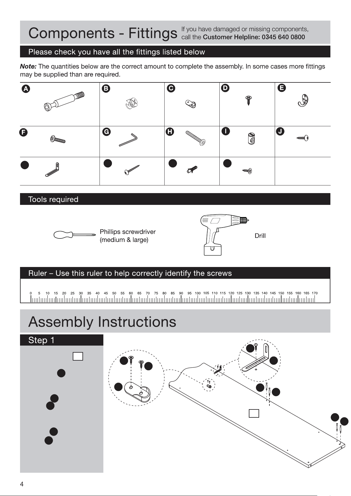
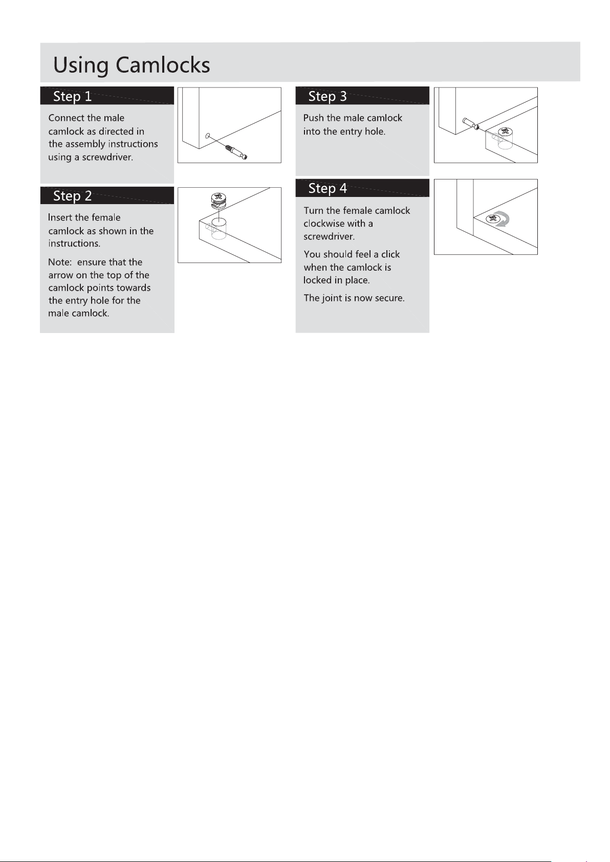
Male Camlock x 8
Female Camlock x 8
Rail Bracket x 2
12mm Screw
x 9
Hooks x 3
35mm Screw
K
Wall Bracket x 2
x 8
L Key x 1
L
35mm Screw
x 2
60mm Screw
M
Wall Plug x 2
x4
14mm Screw
Barrel Nut x 4
N
12mm Screw
x4
x2
1. To Side Panel 1 ,
1
insert 4 x Male
Camlocks A
A
2. Attach 1 x Wall
Bracket K using 1 x
Screw J
K
J
3. Attach 1 x Rail
Bracket C using 2 x
Screw N
C
N
J
N
N
C
1
K
A
A
A
A
Page 6
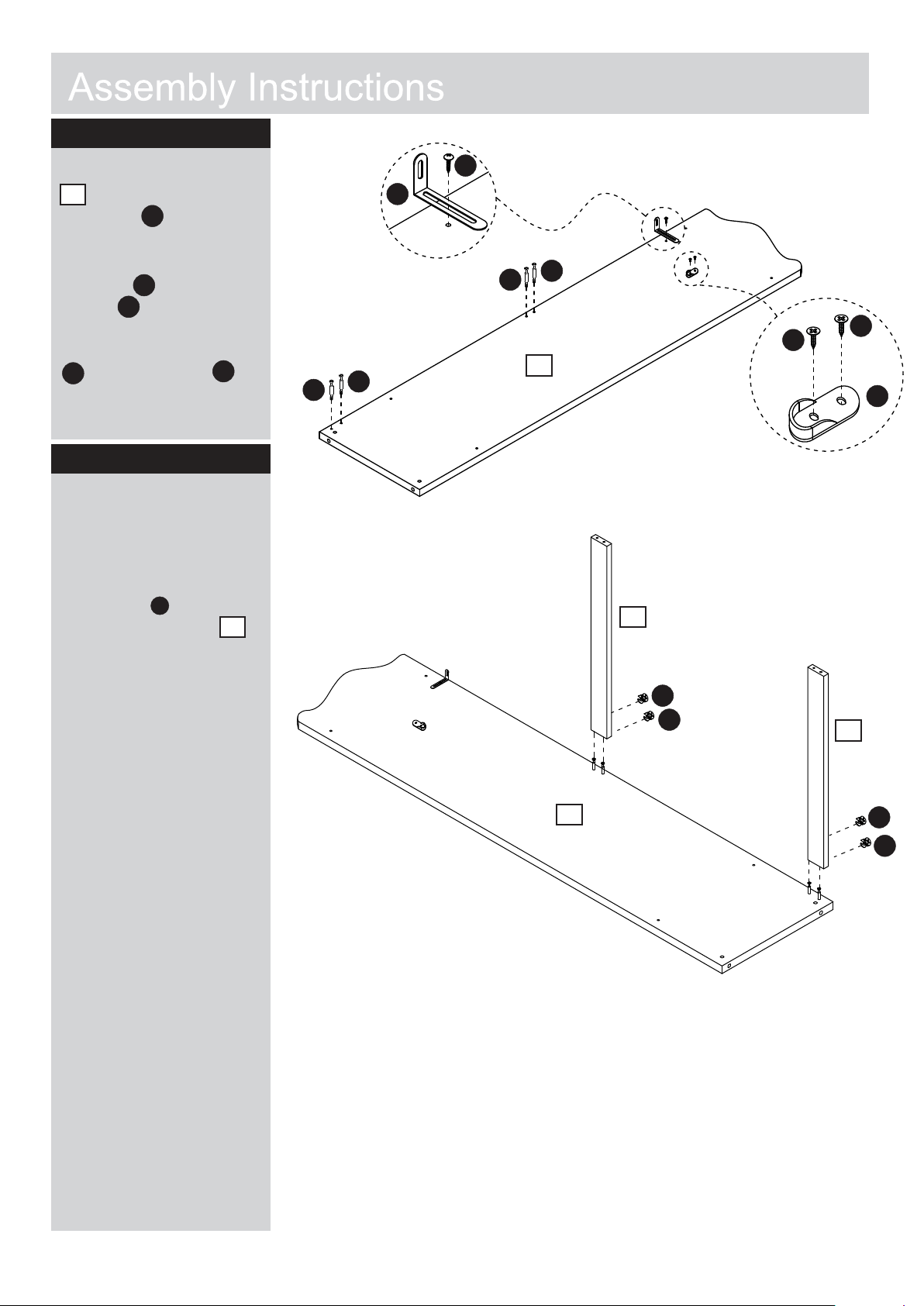
Step 2
1. To Mirrored Side Panel
2
2 , insert 4 x Male
Camlocks
A
2. Attach 1 x Wall
Bracket K using 1 x
Screw J .
K
J
3. Attach 1 x Rail Bracket
C
C using 2 x Screw N
Step 3
1. Locate 2 x Cross
Plinths 3 onto Male
Camlocks as shown.
2. Insert 4 x Female
camlocks into holes
shown in 2 x panel
and tighten with a
suitable screwdriver
Note: For further details,
please see the “using
camlocks” section at the
front of this instruction
B
B
J
K
A
A
N
2
N
3
A
A
3
B
B
N
C
3
1
B
B
5
Page 7
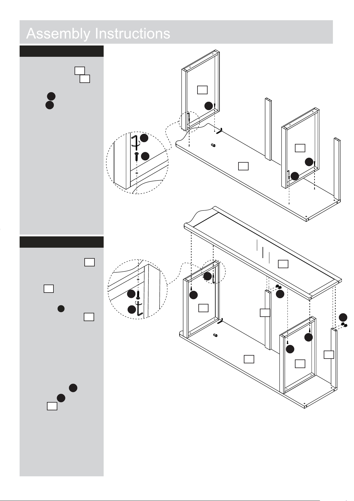
Step 4
1. To Side Panel 1,
connect 2 x Panel 4
1
4
as shown with 4 x
screw F using
L Key G
F
G
Step 5
4
G
F
F
4
1
F
F
1. To Connect Panel 2 ,
Locate male Camlocks
into holes in 2 x Cross
Plinth 3.
3
2. Insert 4 x Female
camlocks into holes
B
B
shown in 2 x panel
and tighten with a
suitable screwdriver
Note: For further details,
please see the “using
camlocks” section at the
front of this instruction
3. Using L Key G insert
4 x Screw F into 2 x
Panels 4
4
G
F
2
F
F
G
3
F
4
3
1
2
B
F
F
4
B
3
6
Page 8
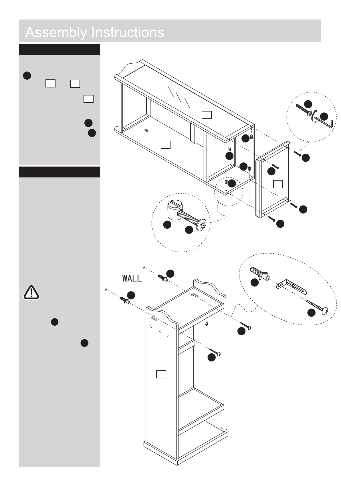
Step 6
1. Insert 4 x Barrel Nuts
I into holes shown in
I
panels 1 and 2 .
1
2
2. Locate Base Panel 5
5
into position.
3. Screw in 4 x Screw H
H
as shown using L Key G
Step 7
The unit is floor
standing, but it is
recommended that
it is secured to the
wall.
1. Move the units into
desired position.
Mark the wall with a
suitable scribe the
position of the xing
hole2.
Warning:
Before driling,check
wall for hidden pipes
and cables.
2
G
1
I
M
M
H
I
I
I
I
M
H
5
H
H
G
H
H
Drill holes and insert 2 x
wall plug D
Secure the brackets to the
wall using 2 x screw
M
L
L
L
L
1
7
Page 9
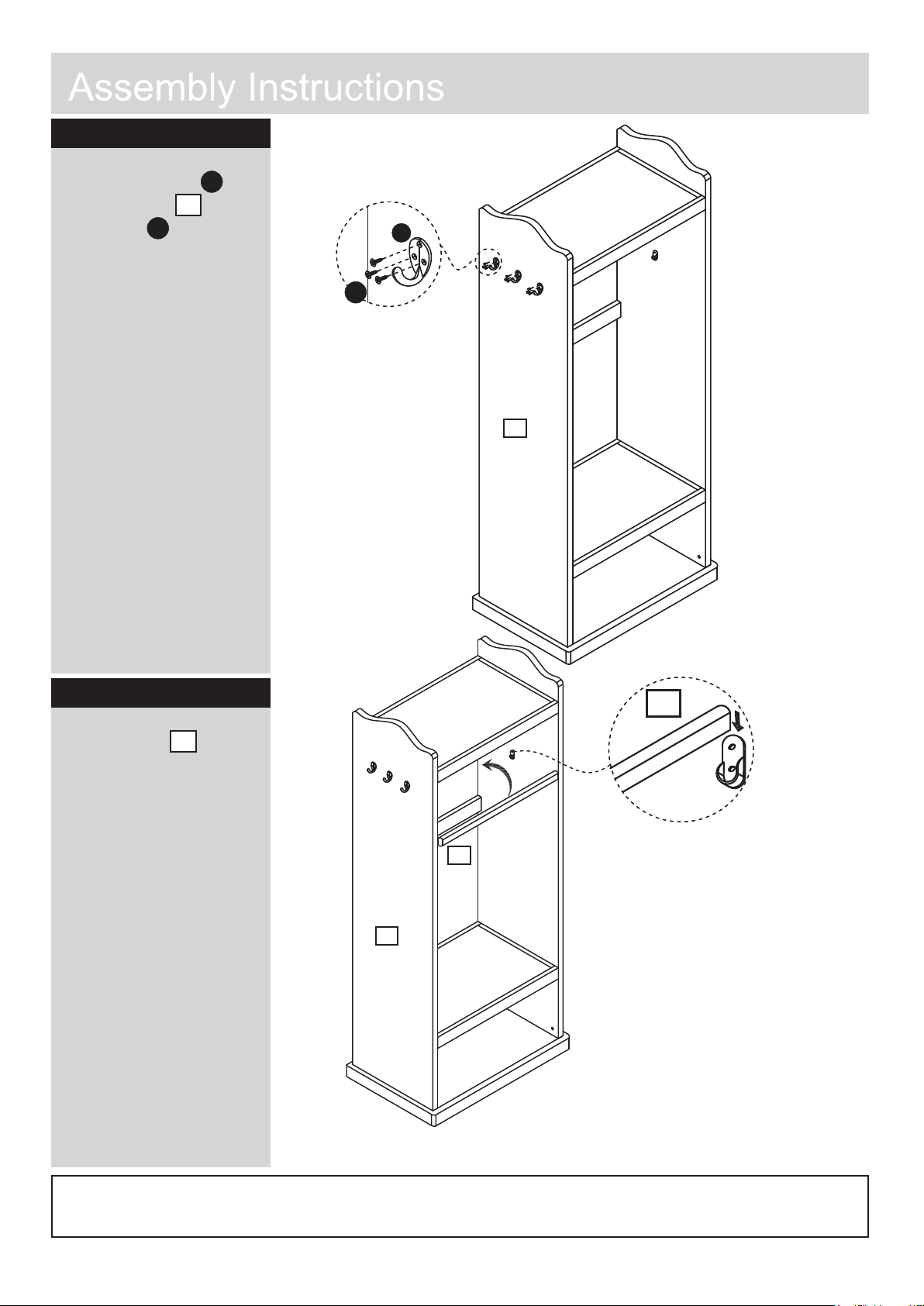
Step 8
1. Add 3 x Hooks E
to Side panel 1 using
3 x Screw D per hook
D
E
1
E
D
D
1
Step 9
1. Locate Rail onto
Brackets as shown
Assembly Complete
6
6
6
1
If you need help or have damaged or missing parts, call the Customer Helpline:
Argos LTD. 489-499 Avebury boulevard, Central Milton Keynes, MK9 2NW
8
0345 640 0800
Page 10
 Loading...