

Page 1

MADE IN
BRITAIN
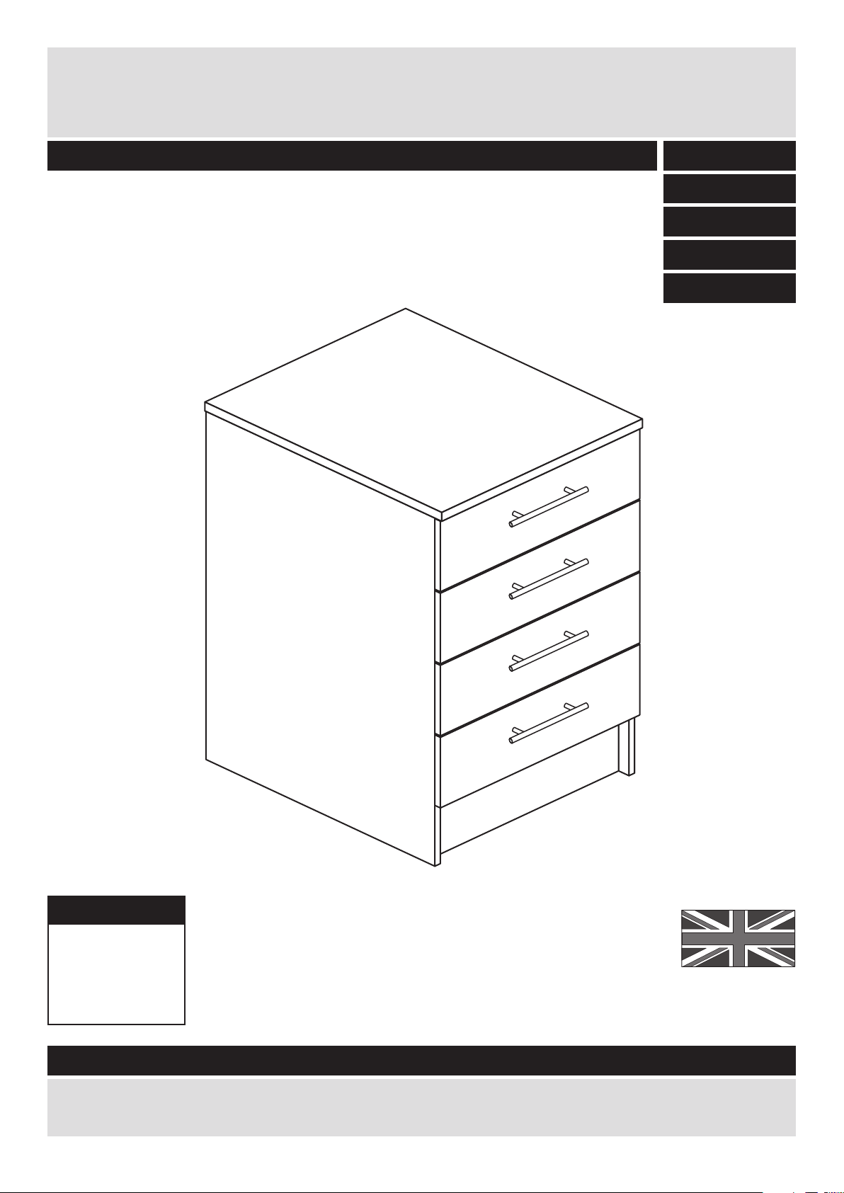
Dimensions
Width - 50cm
Depth - 59cm
Height - 89.5cm
Athina - 500 Drawer Unit
Assembly Instructions - Please keep for future reference
If you need help or have damaged or missing parts, call the Customer Helpline: 08456 400800
Issue 3 - 25/03/11
Important - Please read these instructions fully before starting assembly
608/0804
608/0921
608/0866
608/2974
608/0983
Page 2

Safety and Care Advice
Important - Please read these instructions fully before starting assembly
• Warning: This unit weighs
approximately 34kgs.
Please lift with care.
• Check you have all the
components and tools listed on
pages 2 and 3.
• Remove all fittings from the
plastic bags and separate them
into their groups.
• Keep children and animals
away from the work area, small
parts could choke if swallowed.
• Make sure you have enough
space to layout the parts before
starting.
• Do not stand or put weight on
the product, this could cause
damage.
• Assemble the item as close to
its final position (in the same
room) as possible.
• Assemble on a soft level
surface to avoid damaging the
unit or your floor (use opened
out unit carton).
1
Care and maintenance
• Only clean using a damp cloth
and mild detergent, do no use
bleach or abrasive cleaners.
• From time to time check that
there are no loose screws on
this unit.
• This product should not be
discarded with household
waste. Take to your local
authority waste disposal centre.
Note: If required the next page
can be cut out and used as
reference throughout the
assembly. Keep this page with
these instructions for future
reference.
• We do not
recommend the
use of power
drill/drivers for
inserting screws,
as this could damage the unit.
Only use hand screwdrivers.
• Safety note: It is
recommended that this unit is
secured to a wall using the
brackets supplied.
• Dispose of all packaging
carefully and responsibly.
Page 3
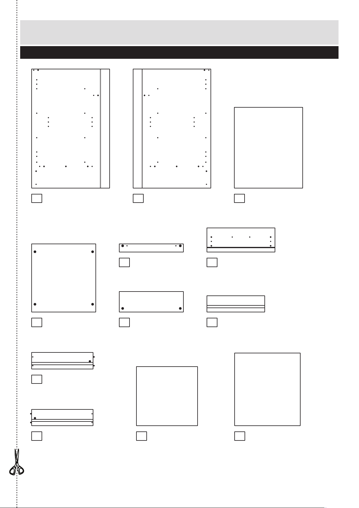
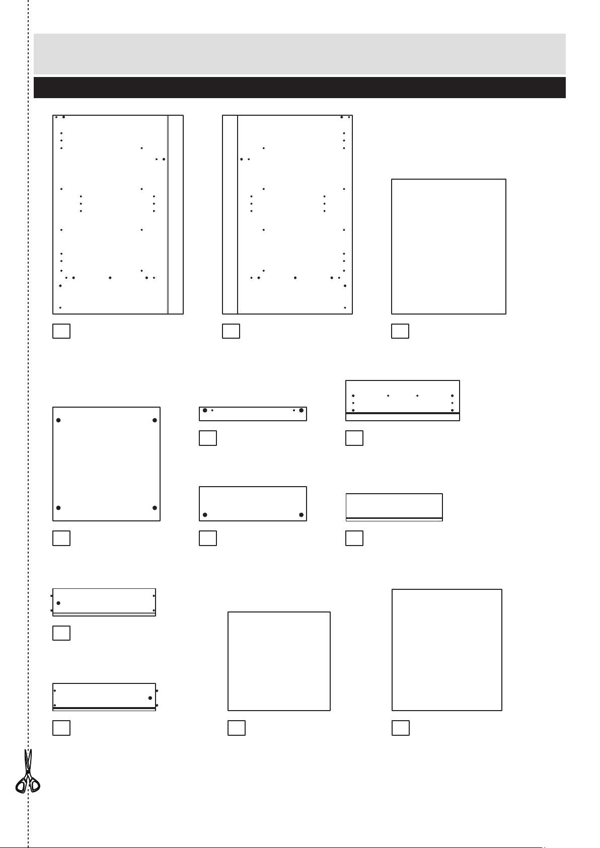
Components - Panels
Please check you have all the panels listed below
2
1
If you have damaged or missing components, call the
Customer Helpline: 08456 400800 quoting the reference
numbers below
Left Side (D0315B)
(870 X 570mm)
Back (X739)
(480 x 533mm)
Rail (D0321A)
(470 x 60mm) x 2
Plinth (D0322A)
(470 x 150mm)
Right Side (D0316B)
(870 x 570mm)
Top (D0338A)
(500 x 590mm)
2 3
Base (D0319A)
(470 X 499mm)
4
5 7
12
6
Drawer Front (D0318A)
(497 x 176mm) x 4
8
Drawer Back (W413BCK)
(422 x 120mm) x 4
9
Left Drawer Side (W413LH)
(450 x 120mm) x 4
10
Right Drawer Side (W413RH)
(450 x 120mm) x 4
11
Drawer Base (T413)
(447 x 433mm) x 4
Page 4

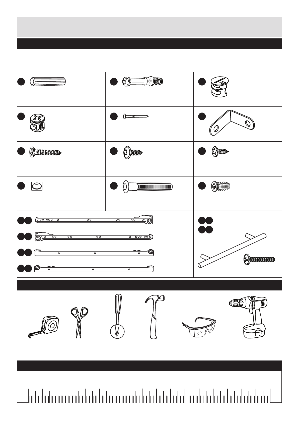
Please check you have all the fittings listed below
3
Components - Fittings
If you have damaged or missing components, call the
Customer Helpline: 08456 400800 quoting the reference
numbers below
Note: The quantities below are the correct amount to complete the assembly. In some cases
more fittings may be supplied than are required.
A
Wooden dowel (F22) x 12
B
Metal dowel (F901) x 18
C
D E F
G H I
Ruler - Use this ruler to help correctly identify the screws
mm 10 20 30 40 50 60 70 80 90 100 110 120 130 140 150 160 170
J
M
Door Buffer (F137) x 8 45mm Screw (F65) x 16
CR Runner
(F133) x 4
CL Runner
(F134) x 4
DR Runner
(F135) x 4
DL Runner
(F136) x 4
Tools required
Rule Scissors Hammer Eye protection
(when using a
hammer or drill)
Cross-head
screwdriver
Electric drill
Large locking
nut (F900) x 10
Bracket (F945) x 4
25mm Screw (F50) x 2
13mm Screw (F63) x 1613mm Screw (F79) x 6
K
Nail (F51) x 8
Small locking
nut (F3) x 8
N
Handle (F847a ) x 4
a
N
Handle Screw (F847b) x 8
b
a
M
b
M
c
M
d
CR
CL
DR
DL
13mm Screw (F52) x 16
L
Page 5
Assembly Instructions
4
If you have damaged or missing components, call the
Customer Helpline: 08456 400800 quoting the reference
numbers below
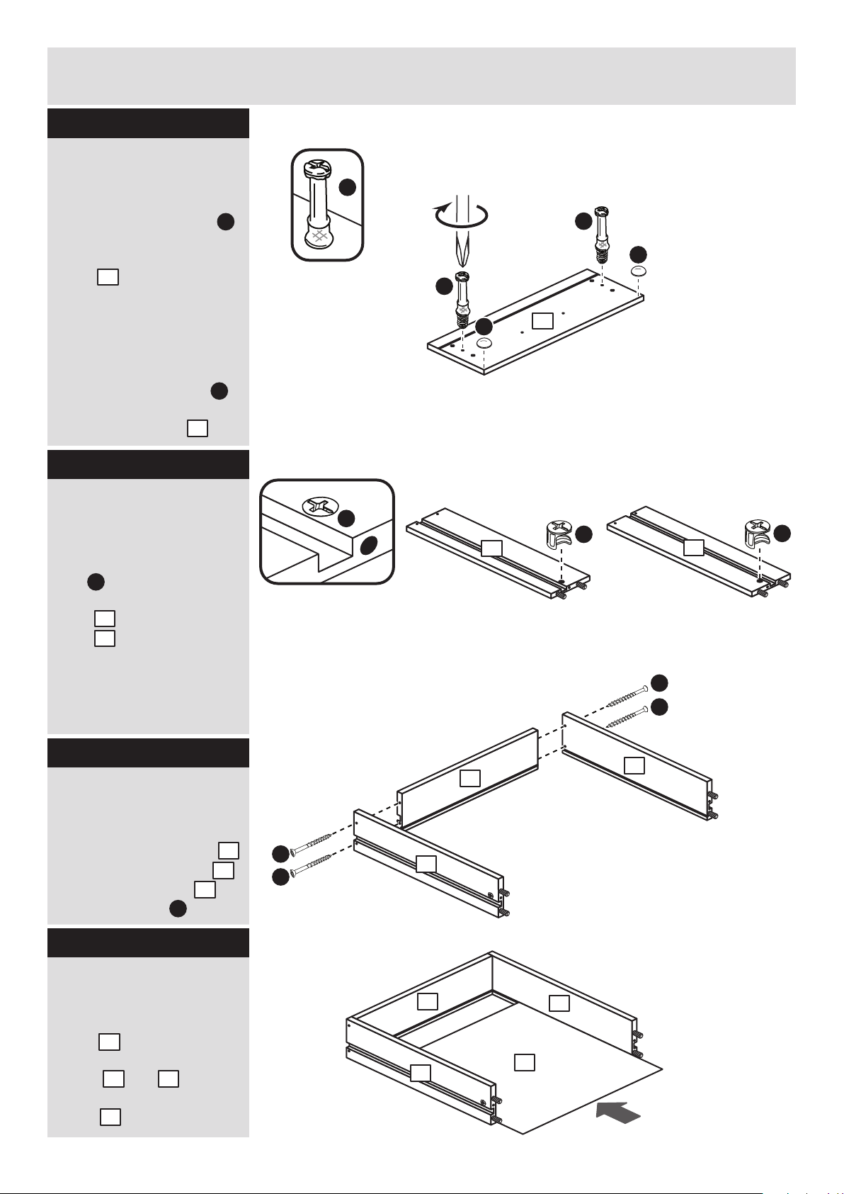
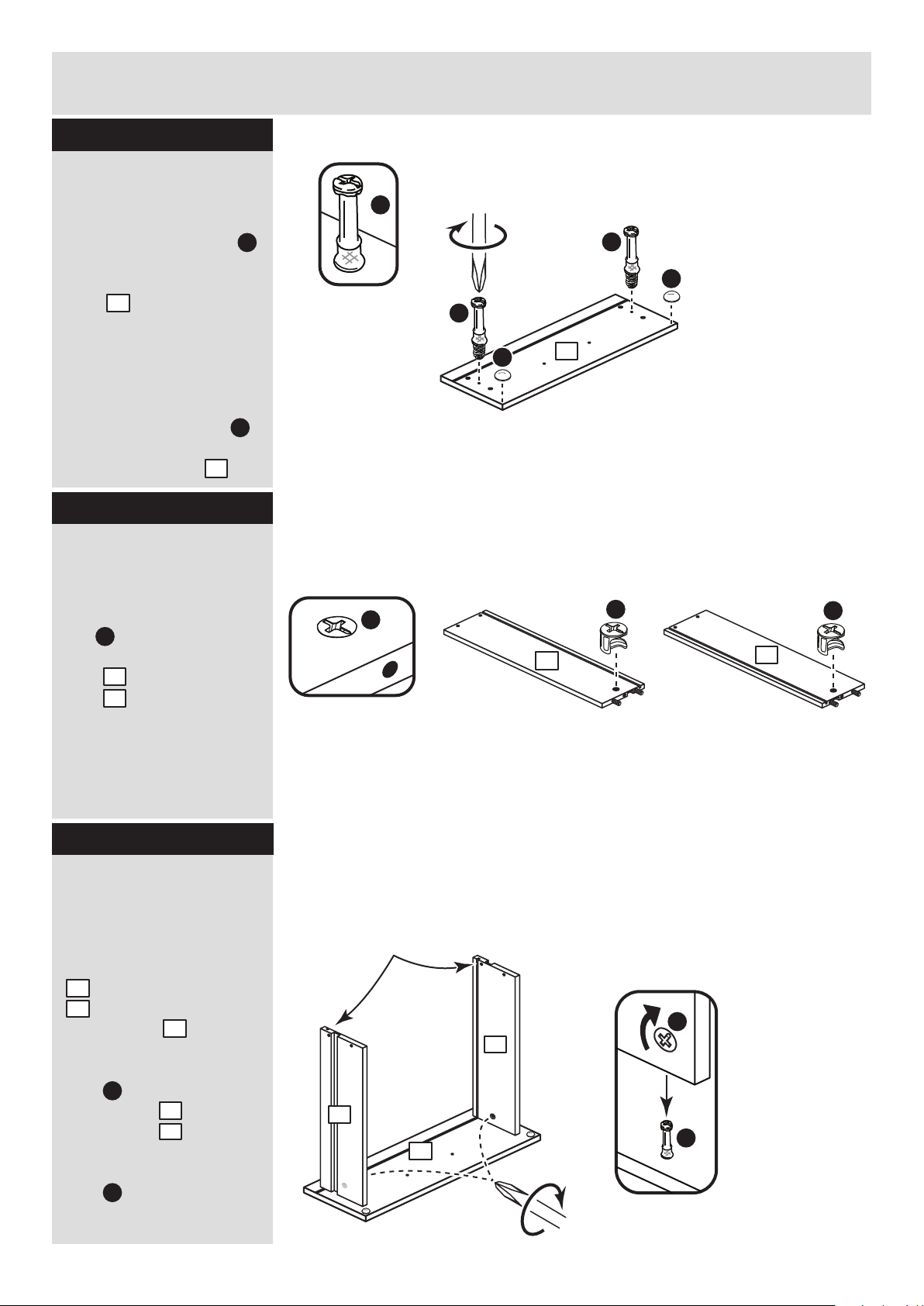
Step 1
B
D
D
Prepare 4 drawer
fronts
Screw 2 metal dowels
into the holes shown on
the back of each drawer
front .
Note: Tighten metal
dowels up fully against
the panels.
Stick a drawer buffer
into the top corners of
each drawer front .
B
7
Prepare the drawer
sides
Insert a small locking
nut into the hole
shown on the left drawer
side and right drawer
side .
Note: Arrow on locking
nut must point towards
hole in edge of panel.
D
9
10
Assemble drawer
sides and back
Fit the left drawer side
and right drawer side
to the drawer back
using 4 screws .
K
9
10
8
Step 2
Step 3
K
K
K
K
B
B
J
B
B
D
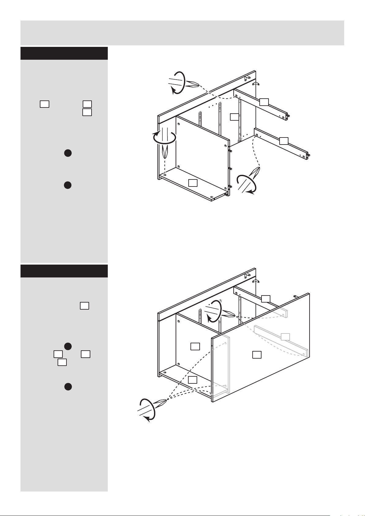
Fit drawer base
Slide the drawer
base along the
grooves of the drawer
sides and into the
groove of the drawer
back .
11
9 10
8
Step 4
7
9
10
9
9
10
10
8
8
11
J
J
7
Page 6
Assembly Instructions
5
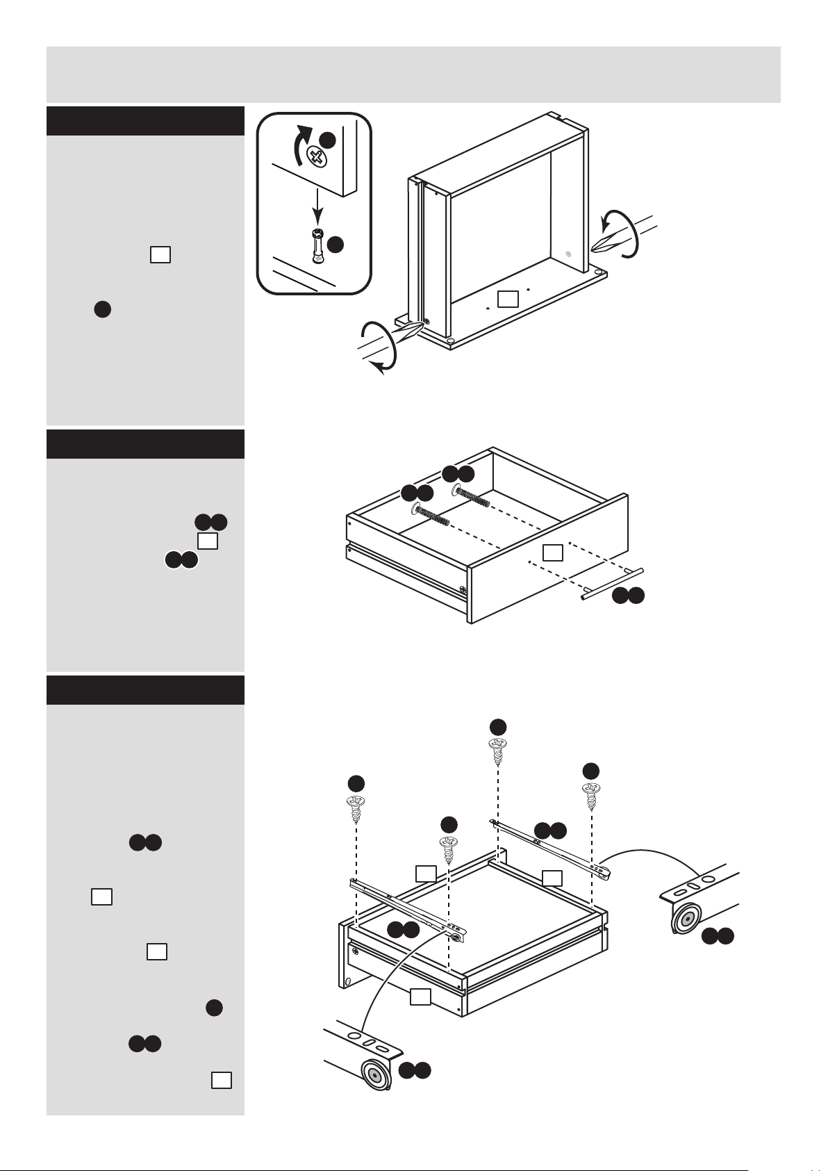
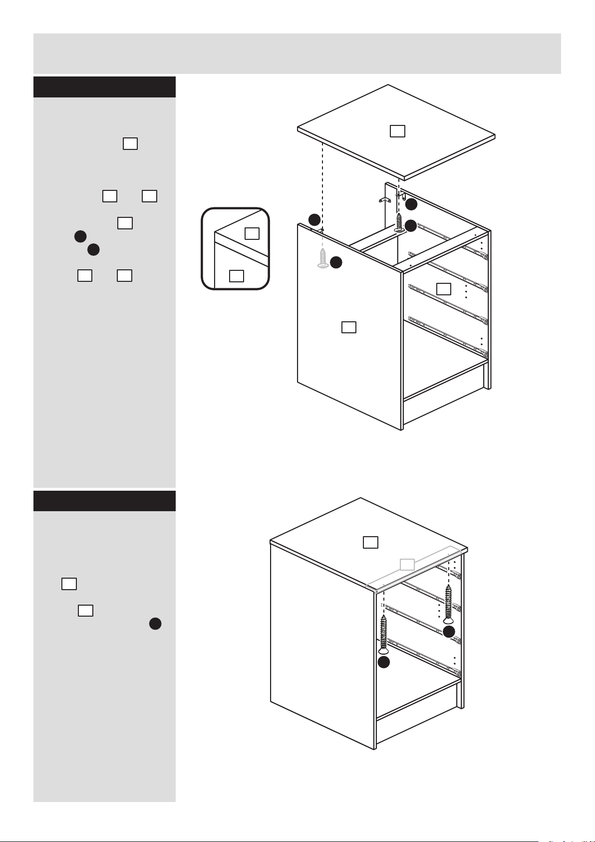
Step 5
Attach drawer front
Turn the drawer
assembly over and push
onto the back of the
drawer front .
Note: Turn locking
nuts clockwise to
secure panels - more
than 1/2 a turn.
7
5
D
B
D
Attach 2 handles
Attach each handle
to the drawer fronts
using 2 screws .
Step 6
Step 7
7
Fit runners to the
drawers
Turn the 4 drawer
assemblies over.
Fit runner ,marked
with ‘DR’, to the bottom
edge of the right drawer
side , making sure
that it is pushed up
against the back of the
drawer front . Use a
bradawl to mark the
fixing positions, then
secure with 2 screws .
Fit runner , marked
‘DL’, to the bottom edge
of the left drawer side
using the same method.
M c
M c
I
N b
N b
N a
I
I
I
M d
M d
10
9
9
M c
10
7
7
I
M d
7
7
N a
N b
DL
DR
DL
Page 7

Assembly Instructions
6
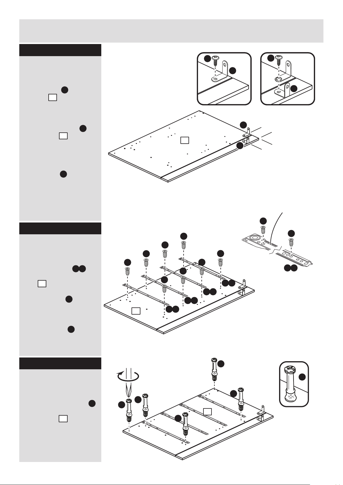
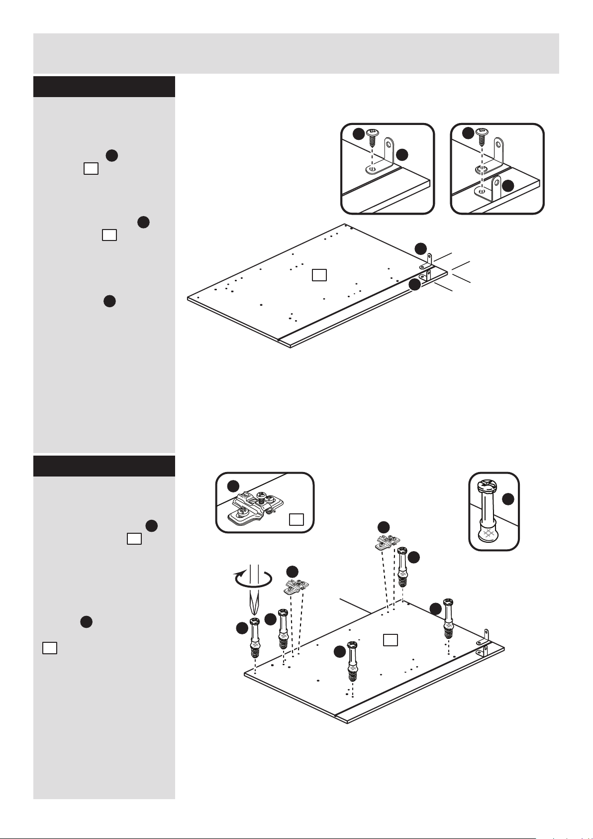
Step 8
1
Step 9
Fit runners to the left
side
Fit the 4 runners
marked ‘CL’ to the left
side .
The 1st screw uses
the 2nd hole in from the
front of the runner.
The 2nd screw uses
the 4th hole in from the
back of the runner.
Step 10
Fit metal dowels to
the left side
Screw 5 metal dowels
into the holes shown on
the left side .
Note: Tighten metal
dowels up fully against
the panels.
Fit 2 brackets to the
left side
Fit a bracket to the
left side , 100mm in
from the back edge, see
diagram.
Fit another bracket to
the left side , 100mm
down from the top edge,
see diagram.
Secure each bracket
using screw .
Note: The brackets must
be flush with the edges
of the panel.
1
F
F
H
1
100mm
100mm
F
F
F
H
F
H
M b
L
L
1
M b
M b
M b
M b
M b
1
B
B
B
B
B
B
B
1
1
CL
CL
L
L
L
L
L
L
L
L
L
L
Page 8

Assembly Instructions
7
Step 11
Step 13
B
B
B
B
B
2
2
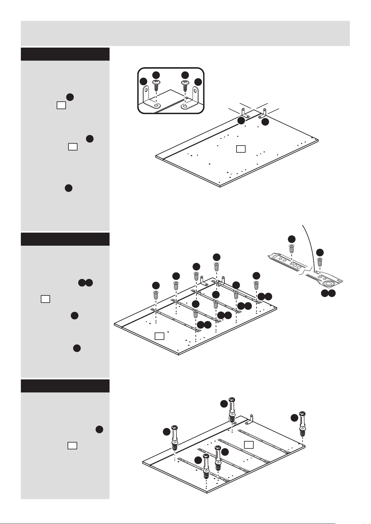
Fit metal dowels to
the right side
Screw 5 metal dowels
into the holes shown on
the right side .
Note: Tighten metal
dowels up fully against
B
2
100mm
100mm
CR
F
F
HH
Fit 2 brackets to the
right side
Fit a bracket to the
right side , 100mm
down from the back
edge, see diagram.
Fit another bracket to
the right side ,
100mm down from the
top edge, see diagram.
Secure each bracket
using screw .
Note: The brackets must
be flush with the edges
of the panel.
2
F
F
H
2
F
F
M a
M a
M a
M a
Step 12
Fit runners to the
right side
Fit the 4 runners
marked ‘CR’ to the right
side .
The 1st screw uses
the 2nd hole in from the
front of the runner.
The 2nd screw uses
the 4th hole in from the
back of the runner.
M a
L
L
2
2
CR
M a
L
L
L
L
L
L
L
L
L
L
Page 9
Assembly Instructions
8
Step 14
A
A
A
A
A
A
Finished
front edge
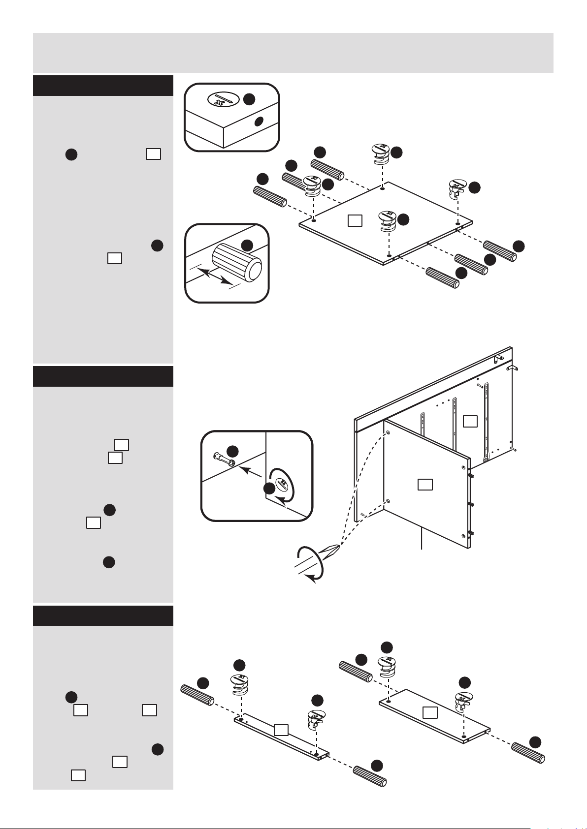
Prepare the base
Insert 4 large locking
nuts into the base
as shown.
Note: Arrow on locking
nut must point towards
hole in edge of panel.
Tap 6 wooden dowels
into the base as
shown.
Note: Wooden dowels
must not stick out from
the edge by more than
10mm or they may
damage other panels.
Step 15
C
C
C
C
C
4
C
4
Fit the base to the
right side
Push the base onto
the right side .
Use a screwdriver to
tighten the 2 large
locking nuts fitted to
the base .
Note: Turn the large
locking nuts as far as
they will go - more than
1/2 a turn.
Step 16
B
4
C
2
4
2
C
4
C
A
C
C
A
5
10mm
A
A
A
C
C
6
Prepare the 2 rails
and plinth
Insert 2 large locking
nuts into each of the
2 rails and plinth
as shown.
Tap 2 wooden dowels
into the 2 rails and
plinth as shown.
C
5
6
5
6
A
4
A
Page 10

Assembly Instructions
9
Step 17
Fit the 2 rails and
plinth
One at a time, push the 2
rails and plinth
onto the right side as
shown.
Use a screwdriver to
tighten the 3 large
locking nuts fitted to
the 3 panels, as shown.
Note: Turn the large
locking nuts as far as
they will go - more than
1/2 a turn.
Note: Support the rail
near the back edge of
the unit until the left side
has been fitted in the
next stage.
2
5
5
6
5 6
2
C
Step 18
Fit the left side
Push the left side
onto the assembly.
Use a screwdriver to
tighten the 5 large
locking nuts fitted to
the base , rails
and plinth .
Note: Turn the large
locking nuts as far as
they will go - more than
1/2 a turn.
5
6
6
1
4
C
5
5
1
4
C
C
Support
this rail
Page 11
Assembly Instructions
10
Step 19
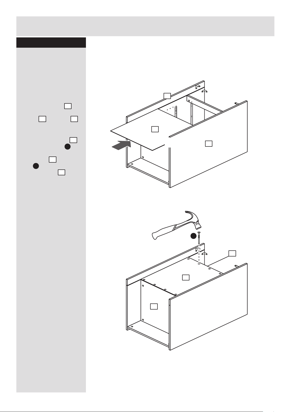
Fit the back
a: Square up the unit by
making sure that
measurement x to x
equals y to y.
b: Slide the back
into the grooves along
the left and right
sides, as shown.
c: Secure the back
by tapping 4 nails
down into the back edge
of the base and 4
nails into the back
edge of the rail .
Stand the unit up for
the next stage.
12
12
E
The measurement from top corner X to bottom corner X must be
equal to the measurement from top corner Y to bottom corner Y
a:
b:
c:
x
y
yy
x
1 2
E
12
4
5
E
4
5
12
1
2
Page 12

Assembly Instructions
Step 20
11
Step 21
Secure the front of
the top
To secure the front of the
top , screw up
through the 2 holes in
the rail at the front of
the unit using screws .
3
H
H
F
F
3
2
1
Fit the top
Position the top onto
the unit, making sure
that the back edge is
flush with the back edge
of the sides and .
Secure the top using
screw through the 2
brackets fitted at the
top edge of the side
panels and .
H
3
2
1
3
F
2
1
3
1
3
5
5
G
G
G
Page 13
Assembly Instructions
12
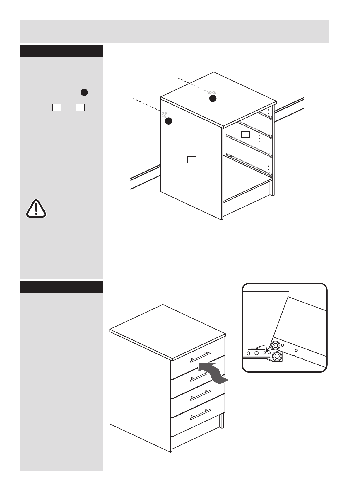
Step 22
Secure the unit to the
wall
Using the brackets
fitted to the back edge of
the sides and
screw the unit to the
wall.
Fixings are not supplied
as they will need to suit
the wall type, and the
length of screw will
depend on the distance
of the back of the Unit to
the wall.
Warning: Take
care when
drilling the wall
that you do not drill into
any pipes, wires etc. If in
doubt, consult an expert.
1
2
F
2
1
F
F
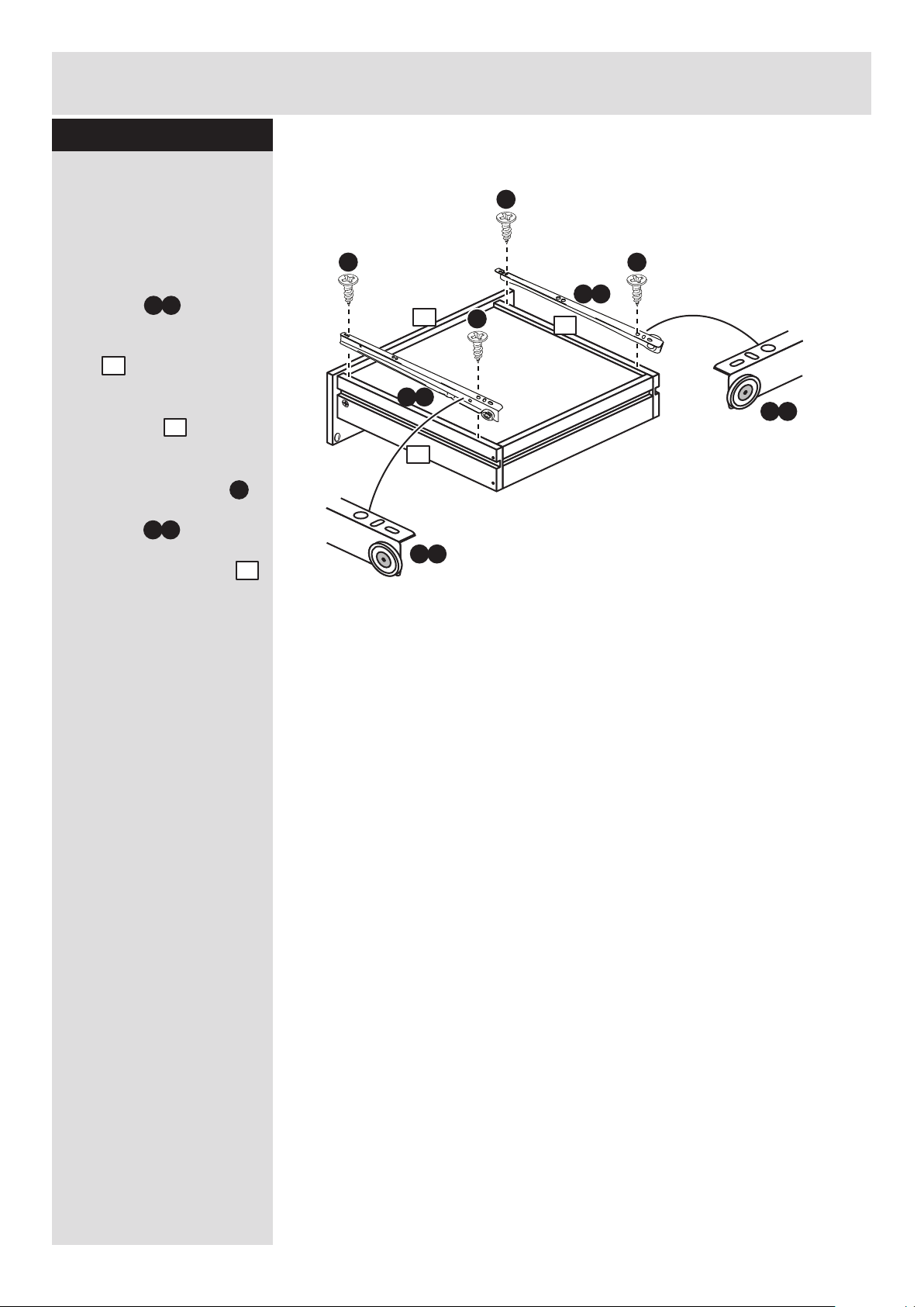
Side
panel
Drawer
side
Step 23
Fit the drawers
Slide the wheels on the
runners fitted to the
drawer sides over the
wheels on the runners
fitted to the side panels
and push the drawer into
position.
Page 14
Assembly Instructions
13
If you need help or have damaged or missing parts, call the Customer Helpline: 08456 400800
and quote the reference numbers on the component pages.
Argos Ltd, 489-499 Avebury Boulevard, Central Milton Keynes, MK9 2NW
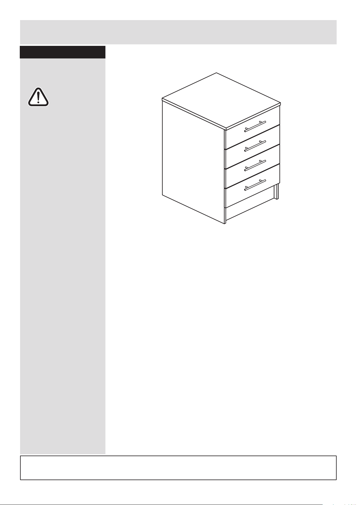
Step 24
Assembly is complete
Warning: The
unit is heavy.
Lift with care.
Page 15

Page 16

ALR2456
Page 17
MADE IN
BRITAIN
Dimensions
Width - 50cm
Depth - 59cm
Height - 89.5cm
Athina - 500 Drawer Unit
Assembly Instructions - Please keep for future reference
If you need help or have damaged or missing parts, call the Customer Helpline: 03456 400800
Issue 4 - 11/03/15
Important - Please read these instructions fully before starting assembly
608/0804
608/0921
608/0866
608/2974
608/0983
Page 18
Safety and Care Advice
Important - Please read these instructions fully before starting assembly
• Warning: This unit weighs
approximately 34kgs.
Please lift with care.
• Check you have all the
components and tools listed on
pages 2 and 3.
• Remove all fittings from the
plastic bags and separate them
into their groups.
• Keep children and animals
away from the work area, small
parts could choke if swallowed.
• Make sure you have enough
space to layout the parts before
starting.
• Do not stand or put weight on
the product, this could cause
damage.
• Assemble the item as close to
its final position (in the same
room) as possible.
• Assemble on a soft level
surface to avoid damaging the
unit or your floor (use opened
out unit carton).
1
Care and maintenance
• Only clean using a damp cloth
and mild detergent, do no use
bleach or abrasive cleaners.
• From time to time check that
there are no loose screws on
this unit.
• This product should not be
discarded with household
waste. Take to your local
authority waste disposal centre.
Note: If required the next page
can be cut out and used as
reference throughout the
assembly. Keep this page with
these instructions for future
reference.
• We do not
recommend the
use of power
drill/drivers for
inserting screws,
as this could damage the unit.
Only use hand screwdrivers.
• Safety note: It is
recommended that this unit is
secured to a wall using the
brackets supplied.
• Dispose of all packaging
carefully and responsibly.
Page 19
Components - Panels
Please check you have all the panels listed below
2
1
If you have damaged or missing components, call the
Customer Helpline: 03456 400800 quoting the reference
numbers below
Left Side (D0315B)
(870 X 570mm)
Back (X739)
(480 x 533mm)
Rail (D0321A)
(470 x 60mm) x 2
Plinth (D0322A)
(470 x 150mm)
Right Side (D0316B)
(870 x 570mm)
Top (D0338A)
(500 x 590mm)
2 3
Base (D0319A)
(470 X 499mm)
4
5 7
12
6
Drawer Front (D0318A)
(497 x 176mm) x 4
8
9
10 11
Drawer Base (T413)
(447 x 433mm) x 4
Left Drawer Side (W450-120LH)
(450 x 120mm) x 4
Right Drawer Side (W450-120RH)
(450 x 120mm) x 4
Drawer Back (W422-120)
(422 x 120mm) x 4
Page 20
Please check you have all the fittings listed below
3
Components - Fittings
If you have damaged or missing components, call the
Customer Helpline: 03456 400800 quoting the reference
numbers below
Note: The quantities below are the correct amount to complete the assembly. In some cases
more fittings may be supplied than are required.
A
Wooden dowel (F22) x 12
B
Metal dowel (F901) x 18
C
D E F
G H I
Ruler - Use this ruler to help correctly identify the screws
mm 10 20 30 40 50 60 70 80 90 100 110 120 130 140 150 160 170
J
M
Door Buffer (F137) x 8
CR Runner
(F133) x 4
CL Runner
(F134) x 4
DR Runner
(F135) x 4
DL Runner
(F136) x 4
Tools required
Rule Scissors Hammer Eye protection
(when using a
hammer or drill)
Cross-head
screwdriver
Electric drill
Large locking
nut (F900) x 10
Bracket (F945) x 4
25mm Screw (F50) x 2
13mm Screw (F63) x 1613mm Screw (F79) x 6
K
Nail (F51) x 8
Small locking
nut (F3) x 8
N
Handle (F847a ) x 4
a
N
Handle Screw (F847b) x 8
b
a
M
b
M
c
M
d
CR
CL
DR
DL
13mm Screw (F52) x 16
L
Knock-in Peg (F171GY) x 16
Page 21
7
Assembly Instructions
4
If you have damaged or missing components, call the
Customer Helpline: 03456 400800 quoting the reference
numbers below
Step 1
B
Prepare 4 drawer
fronts
Screw 2 metal dowels
into the holes shown on
the back of each drawer
front .
Note: Tighten metal
dowels up fully against
the panels.
Stick a drawer buffer
into the top corners of
each drawer front .
B
7
Prepare the drawer
sides
Insert a small locking
nut into the hole
shown on the left drawer
side and right drawer
side .
Note: The arrow on the
locking nut must point
towards the hole in the
edge of the panel.
D
9
10
Step 2
B
B
J
B
B
7
J
J
7
10
D
9
D
D
D
Step 3
Attach the drawer
sides to the drawer
fronts
Push the left drawer side
. and right drawer side
. onto the back of the
drawer front .
Turn the small locking
nuts on the left
drawer side and right
drawer side .
Note: Turn the locking
nuts clockwise to
secure panels - more
than 1/2 a turn.
9
10
7
D
D
9
10
Groove
9
10
B
x 4
x 4 x 4
x 4
Page 22

Assembly Instructions
5
Step 4
Attach the handles
Attach a handle to
each drawer front
using 2 screws .
Step 6
7
N a
N b
7
K
K
Fit the drawer bases
Slide the drawer base
down the grooves in the
drawer sides and
and down into the
groove in the drawer
front .
Step 5
Fit the drawer backs
Fit the drawer back
between the drawer
sides and .
Make sure that the
drawer base fits into
the groove in the drawer
back .
Hold the drawer back
in position and tap the
knock-in pegs
through the holes in the
drawer sides and .
11
9 10
7
8
9 10
11
8
8
K
9 10
9
10
11
K
K
8
10
9
11
N b
N b
7
N a
x 4
x 4
x 4
Page 23
Assembly Instructions
6
Step 7
Fit runners to the
drawers
Turn the 4 drawer
assemblies over.
Fit runner ,marked
with ‘DR’, to the bottom
edge of the right drawer
side , making sure
that it is pushed up
against the back of the
drawer front . Use a
bradawl to mark the
fixing positions, then
secure with 2 screws .
Fit runner , marked
‘DL’, to the bottom edge
of the left drawer side
using the same method.
10
9
9
M c
10
7
7
I
M d
x 4
M c
M c
I
I
M d
M d
I
I
DL
DR
DL
Page 24
Assembly Instructions
7
Step 8
1
Step 9
Fit runners to the left
side
Fit the 4 runners
marked ‘CL’ to the left
side .
The 1st screw uses
the 2nd hole in from the
front of the runner.
The 2nd screw uses
the 4th hole in from the
back of the runner.
Step 10
Fit metal dowels to
the left side
Screw 5 metal dowels
into the holes shown on
the left side .
Note: Tighten metal
dowels up fully against
the panels.
Fit 2 brackets to the
left side
Fit a bracket to the
left side , 100mm in
from the back edge, see
diagram.
Fit another bracket to
the left side , 100mm
down from the top edge,
see diagram.
Secure each bracket
using screw .
Note: The brackets must
be flush with the edges
of the panel.
1
F
F
H
1
100mm
100mm
F
F
F
H
F
H
M b
L
L
1
M b
M b
M b
M b
M b
1
B
B
B
B
B
B
B
1
1
CL
CL
L
L
L
L
L
L
L
L
L
L
Page 25
Assembly Instructions
8
Step 11
Step 13
B
B
B
B
B
2
2
Fit metal dowels to
the right side
Screw 5 metal dowels
into the holes shown on
the right side .
Note: Tighten metal
dowels up fully against
B
2
100mm
100mm
CR
F
F
HH
Fit 2 brackets to the
right side
Fit a bracket to the
right side , 100mm
down from the back
edge, see diagram.
Fit another bracket to
the right side ,
100mm down from the
top edge, see diagram.
Secure each bracket
using screw .
Note: The brackets must
be flush with the edges
of the panel.
2
F
F
H
2
F
F
M a
M a
M a
M a
Step 12
Fit runners to the
right side
Fit the 4 runners
marked ‘CR’ to the right
side .
The 1st screw uses
the 2nd hole in from the
front of the runner.
The 2nd screw uses
the 4th hole in from the
back of the runner.
M a
L
L
2
2
CR
M a
L
L
L
L
L
L
L
L
L
L
Page 26

Assembly Instructions
9
Step 14
A
A
A
A
A
A
Finished
front edge
Prepare the base
Insert 4 large locking
nuts into the base
as shown.
Note: Arrow on locking
nut must point towards
hole in edge of panel.
Tap 6 wooden dowels
into the base as
shown.
Note: Wooden dowels
must not stick out from
the edge by more than
10mm or they may
damage other panels.
Step 15
C
C
C
C
C
4
C
4
Fit the base to the
right side
Push the base onto
the right side .
Use a screwdriver to
tighten the 2 large
locking nuts fitted to
the base .
Note: Turn the large
locking nuts as far as
they will go - more than
1/2 a turn.
Step 16
B
4
C
2
4
2
C
4
C
A
C
C
A
5
10mm
A
A
A
C
C
6
Prepare the 2 rails
and plinth
Insert 2 large locking
nuts into each of the
2 rails and plinth
as shown.
Tap 2 wooden dowels
into the 2 rails and
plinth as shown.
C
5
6
5
6
A
4
A
Page 27
Assembly Instructions
10
Step 17
Fit the 2 rails and
plinth
One at a time, push the 2
rails and plinth
onto the right side as
shown.
Use a screwdriver to
tighten the 3 large
locking nuts fitted to
the 3 panels, as shown.
Note: Turn the large
locking nuts as far as
they will go - more than
1/2 a turn.
Note: Support the rail
near the back edge of
the unit until the left side
has been fitted in the
next stage.
2
5
5
6
5 6
2
C
Step 18
Fit the left side
Push the left side
onto the assembly.
Use a screwdriver to
tighten the 5 large
locking nuts fitted to
the base , rails
and plinth .
Note: Turn the large
locking nuts as far as
they will go - more than
1/2 a turn.
5
6
6
1
4
C
5
5
1
4
C
C
Support
this rail
Page 28

Assembly Instructions
11
Step 19
Fit the back
a: Square up the unit by
making sure that
measurement x to x
equals y to y.
b: Slide the back
into the grooves along
the left and right
sides, as shown.
c: Secure the back
by tapping 4 nails
down into the back edge
of the base and 4
nails into the back
edge of the rail .
Stand the unit up for
the next stage.
12
12
E
The measurement from top corner X to bottom corner X must be
equal to the measurement from top corner Y to bottom corner Y
a:
b:
c:
x
y
yy
x
1 2
E
12
4
5
E
4
5
12
1
2
Page 29
Assembly Instructions
Step 20
12
Step 21
Secure the front of
the top
To secure the front of the
top , screw up
through the 2 holes in
the rail at the front of
the unit using screws .
3
H
H
F
F
3
2
1
Fit the top
Position the top onto
the unit, making sure
that the back edge is
flush with the back edge
of the sides and .
Secure the top using
screw through the 2
brackets fitted at the
top edge of the side
panels and .
H
3
2
1
3
F
2
1
3
1
3
5
5
G
G
G
Page 30

Assembly Instructions
13
Step 22
Secure the unit to the
wall
Using the brackets
fitted to the back edge of
the sides and
screw the unit to the
wall.
Fixings are not supplied
as they will need to suit
the wall type, and the
length of screw will
depend on the distance
of the back of the Unit to
the wall.
Warning: Take
care when
drilling the wall
that you do not drill into
any pipes, wires etc. If in
doubt, consult an expert.
1
2
F
2
1
F
F
Side
panel
Drawer
side
Step 23
Fit the drawers
Slide the wheels on the
runners fitted to the
drawer sides over the
wheels on the runners
fitted to the side panels
and push the drawer into
position.
Page 31

Assembly Instructions
14
If you need help or have damaged or missing parts, call the Customer Helpline: 03456 400800
and quote the reference numbers on the component pages.
Argos Ltd, 489-499 Avebury Boulevard, Central Milton Keynes, MK9 2NW
Step 24
Assembly is complete
Warning: The
unit is heavy.
Lift with care.
Page 32

ALR2456
Page 33

MADE IN
BRITAIN
Dimensions
Width - 100cm
Depth - 59cm
Height - 89.5cm
Athina - 1000 Base Unit
Assembly Instructions - Please keep for future reference
If you need help or have damaged or missing parts, call the Customer Helpline: 08456 400800
Issue 3 - 01/02/12
Important - Please read these instructions fully before starting assembly
608/0811
608/0938
608/0873
608/2981
608/0990
Page 34

Safety and Care Advice
Important - Please read these instructions fully before starting assembly
• Warning: This unit weighs
approximately 42kgs.
Please lift with care.
• Check you have all the
components and tools listed on
pages 2 and 3.
• Remove all fittings from the
plastic bags and separate them
into their groups.
• Keep children and animals
away from the work area, small
parts could choke if swallowed.
• Make sure you have enough
space to layout the parts before
starting.
• Do not stand or put weight on
the product, this could cause
damage.
• Assemble the item as close to
its final position (in the same
room) as possible.
• Assemble on a soft level
surface to avoid damaging the
unit or your floor (use opened
out unit carton).
1
Care and maintenance
• Only clean using a damp cloth
and mild detergent, do no use
bleach or abrasive cleaners.
• From time to time check that
there are no loose screws on
this unit.
• This product should not be
discarded with household
waste. Take to your local
authority waste disposal centre.
Note: If required the next page
can be cut out and used as
reference throughout the
assembly. Keep this page with
these instructions for future
reference.
• We do not
recommend the
use of power
drill/drivers for
inserting screws,
as this could damage the unit.
Only use hand screwdrivers.
• Safety note: It is
recommended that this unit is
secured to a wall using the
brackets supplied.
• Dispose of all packaging
carefully and responsibly.
Page 35

Components - Panels
Please check you have all the panels listed below
2
1
If you have damaged or missing components, call the
Customer Helpline: 08456 400800 quoting the reference
numbers below
Door (D0317A)
(716 x 497mm) x 2
2
9
Base (D0323A)
(970 X 499mm)
Shelf (D0324A)
(969 X 427mm)
Top (D0339A)
(1000 x 590mm)
Back (X740)
(980 x 533mm)
3
4 5
6 7
8
10
Left Side (D0315B)
(870 X 570mm)
Right Side (D0316B)
(870 x 570mm)
Rail (D0325A)
(970 x 60mm) x 2
Plinth (D0326A)
(970 x 150mm)
Munting (D0327A)
(689 x 59mm)
Page 36

Please check you have all the fittings listed below
Tools required
3
Components - Fittings
If you have damaged or missing components, call the
Customer Helpline: 08456 400800 quoting the reference
numbers below
Note: The quantities below are the correct amount to complete the assembly. In some cases
more fittings may be supplied than are required.
A
Wooden dowel (F22) x 14
B
Metal dowel (F901) x 10
C
D
Shelf support (F110) x 4
E F
G H I
Rule Scissors Hammer Eye protection
(when using a
hammer or drill)
Cross-head
screwdriver
Nail (F51) x 14
Ruler - Use this ruler to help correctly identify the screws
mm 10 20 30 40 50 60 70 80 90 100 110 120 130 140 150 160 170
J
Door Buffer (F137) x 4
L
Electric drill
Large locking
nut (F900) x 10
Bracket (F945) x 4
25mm Screw (F50) x 4
13mm Screw (F63) x 813mm Screw (F79) x 6
K
Hinge Plate
(F853) x 4
Hinge (F852) x 4
M
Handle (F847a ) x 2
a
M
Handle Screw (F847b) x 4
b N
40mm Screw (F910) x 2
Page 37

Front
edge
Assembly Instructions
4
If you have damaged or missing components, call the
Customer Helpline: 08456 400800 quoting the reference
numbers below
Step 1
B
B
B
B
B
B
1
1
1
K
K
K
Front
edge
Step 2
a:
b:
K
Prepare the left side
a: Fit 2 hinge plates
onto the left side ,
making sure that the slot
is facing towards the
front edge.
b: Screw 5 metal
dowels into the holes
shown on the left side
. .
Note: Tighten metal
dowels up fully against
the panels.
1
B
1
Fit 2 brackets to the
left side
Fit a bracket to the
left side , 100mm in
from the back edge, see
diagram.
Fit another bracket to
the left side , 100mm
down from the top edge,
see diagram.
Secure each bracket
using screw .
Note: The brackets must
be flush with the edges
of the panel.
1
F
F
H
1
100mm
100mm
F
F
F
H
F
H
Page 38

Assembly Instructions
5
Step 3
Step 4
B
B
B
B
B
2
2
Front
edge
K
K
2
K
K
Prepare the right side
a: Fit 2 hinge plates
onto the right side ,
making sure that the slot
is facing towards the
front edge.
b: Screw 5 metal
dowels into the holes
shown on the right side
. .
Note: Tighten metal
dowels up fully against
the panels.
2
B
2
100mm
100mm
F
F
HH
Fit 2 brackets to the
right side
Fit a bracket to the
right side , 100mm
down from the back
edge, see diagram.
Fit another bracket to
the right side ,
100mm down from the
top edge, see diagram.
Secure each bracket
using screw .
Note: The brackets must
be flush with the edges
of the panel.
2
F
F
H
2
F
F
Front
edge
Page 39

Assembly Instructions
6
Prepare the base
Insert 4 large locking
nuts into the base
as shown.
Note: Arrow on locking
nut must point towards
hole in edge of panel.
Tap 6 wooden dowels
into the base as
shown.
Note: Wooden dowels
must not stick out from
the edge by more than
10mm or they may
damage other panels.
Step 5
Step 6
C
C
4
Fit the base to the
right side
Push the base onto
the right side .
Use a screwdriver to
tighten the 2 large
locking nuts fitted to
the base .
Note: Turn the large
locking nuts as far as
they will go - more than
1/2 a turn.
4
2
C
4
C
10mm
A
A
4
A
A
A
C
C
A
A
A
C
C
4
Finished
front edge
B
4
C
2
Page 40

Assembly Instructions
7
Step 7
Step 8
Fit a rail to the right
side
Push one of the rails
onto the right side as
shown.
Use a screwdriver to
tighten the large locking
nut .
Note: Turn the large
locking nuts as far as
they will go - more than
1/2 a turn.
6
2
C
C
A
C
C
A
6
Prepare the 2 rails
and munting
Insert 2 large locking
nuts and 2 wooden
dowels into each of
the 2 rails .
Tap 2 wooden dowels
into the munting .
C
6
8
A
A
8
A
A
2
6
Page 41

Assembly Instructions
8
Step 9
A
A
C
C
7
Prepare the plinth
Insert 2 large locking
nuts and 2 wooden
dowels into the plinth
. .
C
7
A
Fit the munting
Fit the munting to the
rail and base and
secure using 2 screws
. .
8
N
6 4
Step 10
N
8
N
6
4
Page 42

Assembly Instructions
9
Step 11
Step 12
6
Fit the rail and plinth
Push the rail and
plinth onto the right
side as shown.
Use a screwdriver to
tighten the 2 large
locking nuts fitted to
the 2 panels, as shown.
Note: Turn the large
locking nuts as far as
they will go - more than
1/2 a turn.
Note: Support the rail
. until the left side has
been fitted in the next
stage.
7
2
C
C
6
Fit the left side
Push the left side
onto the assembly.
Use a screwdriver to
tighten the 5 large
locking nuts fitted to
the base , rails
and plinth .
Note: Turn the large
locking nuts as far as
they will go - more than
1/2 a turn.
6
7
1
4
C
C
2
6
7
6
6
6
7
4
1
Page 43

Assembly Instructions
10
Step 13
Fit the back
a: Square up the unit by
making sure that
measurement x to x
equals y to y.
b: Slide the back
into the grooves along
the left and right
sides, as shown.
c: Secure the back
by tapping 7 nails
down into the back edge
of the base and 7
nails into the back
edge of the rail .
Stand the unit up for
the next stage.
The measurement from top corner X to bottom corner X must be
equal to the measurement from top corner Y to bottom corner Y
a:
1 2
D
10
4
6
D
10
b:
c:
x
y
y
x
10
10
D
1
2
6
4
Page 44

Assembly Instructions
Step 14
11
Step 15
Secure the front of
the top
To secure the front of the
top , screw up
through the 4 holes in
the rail at the front of
the unit using screws .
Fit the top
Position the top onto
the unit, making sure
that the back edge is
flush with the back edge
of the sides and .
Secure the top using
screw through the 2
brackets fitted at the
top edge of the side
panels and .
H
3
2
1
3
F
2
1
3
6
G
H
F
H
F
G
G
G
G
3
6
3
2
1
Page 45

Assembly Instructions
12
Step 16
Secure the unit to the
wall
Using the brackets
fitted to the back edge of
the sides and
screw the unit to the
wall.
Fixings are not supplied
as they will need to suit
the wall type, and the
length of screw will
depend on the distance
of the back of the Unit to
the wall.
Warning: Take
care when
drilling the wall
that you do not drill into
any pipes, wires etc. If in
doubt, consult an expert.
Step 17
F
2
1
Fit the shelf studs
Push 4 shelf studs
into the holes in the side
panels and at the
desired height.
E
1 2
F
F
E
E
E
E
2
1
2
1
Page 46

Assembly Instructions
13
Step 18
Step 19
Fit the shelf
Manouvre the shelf
into the unit onto the
shelf studs .
5
E
Prepare the 2 doors
Push fit the 2 hinges
into the door .
Secure each hinge with
2 screws .
Note: Before securing
with the screws, make
sure that the hinges are
positioned at 90 degrees
with the front edge of the
door.
I
L
9
9
L
I
I
L
I
I
90
L
5
Page 47

Assembly Instructions
14
Step 20
Small piece of
waste wood
Small piece of
waste wood
ONLY drill
these 2 holes
ONLY drill
these 2 holes
DO NOT drill
these holes
DO NOT drill
these holes
9
9
Drill the handle holes
in the door
Important: Please follow
these instructions
carefully.
Lay the doors down
onto a smooth surface.
Important: Check that
the holes and hinges are
in the same place as the
diagrams.
Note: We recommend
the use of a small piece
of waste wood, placed
behind the hole while
drilling, to reduce the
possibility of any
breakout.
Using the pilot hole in
the rear face of the
door , drill through the
holes indicated opposite,
using a 2.5mm diameter
drill.
Turn the door over
and open out the 2.5mm
holes that you have just
drilled by drilling back
through them with a
5mm drill.
This will be
the left door
This will be
the right door
9
9
9
IMPORTANT
Carefully choose which 2 holes you
need to drill in each of the doors
Page 48

Assembly Instructions
Step 21
screw A
a: b:
c: d:
A
screw B
L
L
LL
K
K
K
K
e:
Fit doors and handles
2 people are needed
here
Note: The easiest way to
attach the door is to
fit the top hinge first,
then align and fit the
other hinges.
a: Push the hinge
onto the front part of the
hinge plate .
b: Keep the hinge
FLAT against the hinge
plate as you slide it
across as far as it will go.
Tighten screw A.
c: The hinge must be
flat against the hinge
plate prior to any
adjustment.
d: The hinge must
NOT be AT AN ANGLE
to the hinge plate
when assembled.
This would indicate that
the recess at the bottom
of screw B had not
located in the
slot in the hinge
plate and the
hinge would not
be secure.
Remove the
hinge from the
hinge plate and
then re-assemble
being careful to
follow
instructions a-c.
e: Attach a
handle to the door
. using 2 screws .
L
L
L
K
K
K
L
K
9
M a
9
M b
9
M a
M b
M b
15
M a
Page 49

Assembly Instructions
16
Step 22
Adjust the doors if
needed
a: Height adjustment.
Loosen screws A on
hinge plates and move
door up or down as
required.
Retighten screw A.
b: Forward and Back
adjustment.
Loosen screw B on hinge
plate and move door in
or out as required.
Retighten screw B.
c: Sideways
adjustment.
To move door ‘out’
loosen screw C.
To move door ‘in’ tighten
screw C
Fit the door buffers to
both doors
Stick a door buffer
onto each corner of the
door so that they hit
the edge of the side
panel when the door is
closed.
Step 23
J
9
a:
b:
c:
A
A
B
C
9
J
J
Page 50

Assembly Instructions
17
If you need help or have damaged or missing parts, call the Customer Helpline: 08456 400800
and quote the reference numbers on the component pages.
Argos Ltd, 489-499 Avebury Boulevard, Central Milton Keynes, MK9 2NW
Step 24
Assembly is complete
Warning: The
unit is heavy.
Lift with care.
Page 51

Page 52

ALR2458
Page 53

MADE IN
BRITAIN
Dimensions
Width - 100cm
Depth - 59cm
Height - 89.5cm
Athina - 1000 Sink Unit
Assembly Instructions - Please keep for future reference
If you need help or have damaged or missing parts, call the Customer Helpline: 08456 400800
Issue 2 - 25/03/11
Important - Please read these instructions fully before starting assembly
656/4069
656/4083
656/4076
633/3726
656/4090
Page 54

Safety and Care Advice
Important - Please read these instructions fully before starting assembly
• Warning: This unit weighs
approximately 36kgs.
Please lift with care.
• Check you have all the
components and tools listed on
pages 2 and 3.
• Remove all fittings from the
plastic bags and separate them
into their groups.
• Keep children and animals
away from the work area, small
parts could choke if swallowed.
• Make sure you have enough
space to layout the parts before
starting.
• Do not stand or put weight on
the product, this could cause
damage.
• Assemble the item as close to
its final position (in the same
room) as possible.
• Assemble on a soft level
surface to avoid damaging the
unit or your floor (use opened
out unit carton).
1
Care and maintenance
• Only clean using a damp cloth
and mild detergent, do no use
bleach or abrasive cleaners.
• From time to time check that
there are no loose screws on
this unit.
• This product should not be
discarded with household
waste. Take to your local
authority waste disposal centre.
Note: If required the next page
can be cut out and used as
reference throughout the
assembly. Keep this page with
these instructions for future
reference.
• We do not
recommend the
use of power
drill/drivers for
inserting screws,
as this could damage the unit.
Only use hand screwdrivers.
• Safety note: It is
recommended that this unit is
secured to a wall using the
bracket supplied.
• Dispose of all packaging
carefully and responsibly.
Page 55

Components - Panels
Please check you have all the panels listed below
2
1
If you have damaged or missing components, call the
Customer Helpline: 08456 400800 quoting the reference
numbers below
Door (D0317A)
(716 x 497mm) x 2
2
9
Base (D0323A)
(970 X 499mm)
Shelf (D0324A)
(969 X 427mm)
Rail (D0325A)
(970 x 60mm) x 2
Plinth (D0326A)
(970 x 150mm)
Back (X740)
(980 x 533mm)
Munting (D0327A)
(689 x 60mm)
3
4 5
6 7
8
10
Sink Top (D0340A)
(1000 x 590mm)
Left Side (D0315B)
(870 X 570mm)
Right Side (D0316B)
(870 x 570mm)
Page 56

Please check you have all the fittings listed below
Tools required
3
Components - Fittings
If you have damaged or missing components, call the
Customer Helpline: 08456 400800 quoting the reference
numbers below
Note: The quantities below are the correct amount to complete the assembly. In some cases
more fittings may be supplied than are required.
A
Wooden dowel (F22) x 14
B
Metal dowel (F901) x 10
C
D
Shelf support (F110) x 4
E F
G H I
Rule Scissors Hammer Eye protection
(when using a
hammer or drill)
Cross-head
screwdriver
Nail (F51) x 14
Ruler - Use this ruler to help correctly identify the screws
mm 10 20 30 40 50 60 70 80 90 100 110 120 130 140 150 160 170
J
Door Buffer (F137) x 4
L
Electric drill
Large locking
nut (F900) x 10
Bracket (F945) x 4
25mm Screw (F50) x 4 13mm Screw (F63) x 813mm Screw (F79) x 6
K
Hinge Plate
(F853) x 4
Hinge (F852) x 4
M
Handle (F847a ) x 2
a
M
Handle Screw (F847b) x 4
b N
40mm Screw (F910) x 2
Flat-head
screwdriver
Page 57
Assembly Instructions
4
If you have damaged or missing components, call the
Customer Helpline: 08456 400800 quoting the reference
numbers below
Step 1
B
B
B
B
B
B
1
1
1
K
K
K
Front
edge
Step 2
a:
b:
K
Prepare the left side
a: Fit 2 hinge plates
onto the left side ,
making sure that the slot
is facing towards the
front edge.
b: Screw 5 metal
dowels into the holes
shown on the left side
. .
Note: Tighten metal
dowels up fully against
the panels.
1
B
1
Fit 2 brackets to the
left side
Fit a bracket to the
left side , 100mm in
from the back edge, see
diagram.
Fit another bracket to
the left side , 100mm
down from the top edge,
see diagram.
Secure each bracket
using screw .
Note: The brackets must
be flush with the edges
of the panel.
1
F
F
H
1
100mm
100mm
F
F
F
H
F
H
Page 58

Assembly Instructions
5
Step 3
Step 4
B
B
B
B
B
2
2
Front
edge
K
K
2
K
K
Prepare the right side
a: Fit 2 hinge plates
onto the right side ,
making sure that the slot
is facing towards the
front edge.
b: Screw 5 metal
dowels into the holes
shown on the right side
. .
Note: Tighten metal
dowels up fully against
the panels.
2
B
2
100mm
100mm
F
F
HH
Fit 2 brackets to the
right side
Fit a bracket to the
right side , 100mm
down from the back
edge, see diagram.
Fit another bracket to
the right side ,
100mm down from the
top edge, see diagram.
Secure each bracket
using screw .
Note: The brackets must
be flush with the edges
of the panel.
2
F
F
H
2
F
F
Page 59

Assembly Instructions
6
Prepare the base
Insert 4 large locking
nuts into the base
as shown.
Note: Arrow on locking
nut must point towards
hole in edge of panel.
Tap 6 wooden dowels
into the base as
shown.
Note: Wooden dowels
must not stick out from
the edge by more than
10mm or they may
damage other panels.
Step 5
Step 6
C
C
4
Fit the base to the
right side
Push the base onto
the right side .
Use a screwdriver to
tighten the 2 large
locking nuts fitted to
the base .
Note: Turn the large
locking nuts as far as
they will go - more than
1/2 a turn.
4
2
C
4
C
10mm
A
A
4
A
A
A
C
C
A
A
A
C
C
4
Finished
front edge
B
4
C
2
Page 60

Assembly Instructions
7
Step 7
Step 8
Fit a rail to the right
side
Push one of the rails
onto the right side as
shown.
Use a screwdriver to
tighten the large locking
nut .
Note: Turn the large
locking nuts as far as
they will go - more than
1/2 a turn.
6
2
C
C
A
C
C
A
6
Prepare the 2 rails
and munting
Insert 2 large locking
nuts and 2 wooden
dowels into each of
the 2 rails .
Tap 2 wooden dowels
into the munting .
C
6
8
A
A
8
A
A
2
6
Page 61

Assembly Instructions
8
Step 9
A
A
C
C
7
Prepare the plinth
Insert 2 large locking
nuts and 2 wooden
dowels into the plinth
. .
C
7
A
Fit the munting
Fit the munting to the
rail and base and
secure using 2 screws
. .
8
N
6 4
Step 10
N
8
N
6
4
Page 62

Assembly Instructions
9
Step 11
Step 12
6
Fit the rail and plinth
Push the rail and
plinth onto the right
side as shown.
Use a screwdriver to
tighten the 2 large
locking nuts fitted to
the 2 panels, as shown.
Note: Turn the large
locking nuts as far as
they will go - more than
1/2 a turn.
Note: Support the rail
. until the left side has
been fitted in the next
stage.
7
2
C
C
6
Fit the left side
Push the left side
onto the assembly.
Use a screwdriver to
tighten the 5 large
locking nuts fitted to
the base , rails
and plinth .
Note: Turn the large
locking nuts as far as
they will go - more than
1/2 a turn.
6
7
1
4
C
C
2
6
7
6
6
6
7
4
1
Page 63

Assembly Instructions
10
Step 13
Fit the back
a: Square up the unit by
making sure that
measurement x to x
equals y to y.
b: Slide the back
into the grooves along
the left and right
sides, as shown.
c: Secure the back
by tapping 7 nails
down into the back edge
of the base and 7
nails into the back
edge of the rail .
The measurement from top corner X to bottom corner X must be
equal to the measurement from top corner Y to bottom corner Y
a:
1 2
D
10
4
6
D
10
b:
c:
x
y
y
x
10
10
D
1
2
6
4
Page 64

Assembly Instructions
Step 14
11
Step 15
Secure the front of
the top
To secure the front of the
top , screw up
through the 4 holes in
the rail at the front of
the unit using screws .
Fit the top
Position the top onto
the unit, making sure
that the back edge is
flush with the back edge
of the sides and .
Secure the top using
screw through the 2
brackets fitted at the
top edge of the side
panels and .
H
3
2
1
3
F
2
1
3
6
G
H
F
H
F
G
G
G
G
6
2
1
3
3
6
Page 65

Assembly Instructions
12
Step 16
Secure the unit to the
wall
Using the brackets
fitted to the back edge of
the sides and
screw the unit to the
wall.
Fixings are not supplied
as they will need to suit
the wall type, and the
length of screw will
depend on the distance
of the back of the Unit to
the wall.
Warning: Take
care when
drilling the wall
that you do not drill into
any pipes, wires etc. If in
doubt, consult an expert.
Step 17
F
2
1
Fit the shelf studs
Push 4 shelf studs
into the holes in the side
panels and at the
desired height.
E
1 2
F
F
E
E
E
E
2
1
2
1
Page 66

Assembly Instructions
13
Step 18
Step 19
Fit the shelf
Manouvre the shelf
into the unit onto the
shelf studs .
5
E
Prepare the 2 doors
Push fit the 2 hinges
into the door .
Secure each hinge with
2 screws .
Note: Before securing
with the screws, make
sure that the hinges are
positioned at 90 degrees
with the front edge of the
door.
I
L
9
9
L
I
I
L
I
I
90
L
5
Page 67

Assembly Instructions
14
Step 20
Small piece of
waste wood
Small piece of
waste wood
ONLY drill
these 2 holes
ONLY drill
these 2 holes
DO NOT drill
these holes
DO NOT drill
these holes
9
9
Drill the handle holes
in the doors
Important: Please follow
these instructions
carefully.
Lay the doors down
onto a smooth surface.
Important: Check that
the holes and hinges are
in the same place as the
diagrams.
Note: We recommend
the use of a small piece
of waste wood, placed
behind the hole while
drilling, to reduce the
possibility of any
breakout.
Using the pilot hole in
the rear face of the
door , drill through the
holes indicated opposite,
using a 2.5mm diameter
drill.
Turn the door over
and open out the 2.5mm
holes that you have just
drilled by drilling back
through them with a
5mm drill.
This will be
the left door
This will be
the right door
9
9
9
Page 68

Assembly Instructions
Step 21
screw A
a: b:
c: d:
A
screw B
L
L
LL
K
K
K
K
e:
Fit doors and handles
2 people are needed
here
Note: The easiest way to
attach the door is to
fit the top hinge first,
then align and fit the
other hinges.
a: Push the hinge
onto the front part of the
hinge plate .
b: Keep the hinge
FLAT against the hinge
plate as you slide it
across as far as it will go.
Tighten screw A.
c: The hinge must be
flat against the hinge
plate prior to any
adjustment.
d: The hinge must
NOT be AT AN ANGLE
to the hinge plate
when assembled.
This would indicate that
the recess at the bottom
of screw B had not
located in the
slot in the hinge
plate and the
hinge would not
be secure.
Remove the
hinge from the
hinge plate and
then re-assemble
being careful to
follow
instructions a-c.
e: Attach a
handle to the door
. using 2 screws .
L
L
L
K
K
K
L
K
9
M a
9
M b
9
M a
M b
M b
15
M a
Page 69

Assembly Instructions
16
Step 22
Adjust the doors if
needed
a: Height adjustment.
Loosen screws A on
hinge plates and move
door up or down as
required.
Retighten screw A.
b: Forward and Back
adjustment.
Loosen screw B on hinge
plate and move door in
or out as required.
Retighten screw B.
c: Sideways
adjustment.
To move door ‘out’
loosen screw C.
To move door ‘in’ tighten
screw C
Fit the door buffers to
both doors
Stick a door buffer
onto each corner of the
door so that they hit
the edge of the side
panel when the door is
closed.
Step 23
J
9
a:
b:
c:
A
A
B
C
9
J
J
Page 70

Assembly Instructions
Step 24
17
Sink Care, Maintenance and Assembly Instructions
Your sink is made of the finest quality stainless steel (CrNi 18/10), DIN1.4301 or AISI 304 (suitable for
food contact).
Keep you sink looking as good as new by following the care and maintenance instructions.
Instructions
For everyday cleaning of the sink, use household detergents suitable for stainless steel.
After each use, rinse the sink with warm water then wipe with a soft dry cloth.
Do not use wire wool.
Do not use chemical ‘silver cleaners’, bleaches or detergents containing chlorine or any of its derivitives.
Warning!
If the sink comes into contact with acidic materials, rinse immediately with plenty of water and wipe with
a soft, dry cloth.
Do not leave rusty objects in contact with the sink. Rust can cause staining, cracking or even
permanent damage to the sink surface.
To avoid staining of the surface do not leave food or other materials with corrosive properties such as
juices, salt, vinegar, mustard etc. on the sink for a long time.
Do not place very hot objects directly on the sink. Place them on a special surface (board) made from
wood or plastic etc.
Avoid scraping the sink basin or draining board with utensils.
Avoid dropping heavy or sharp objects onto the sink surface.
Fit the seal tape
Adhere the seal tape
around the underside of
the edge of the sink,
being careful to lay it
smoothly (without
ridges).
Step 25
Fit the anchor braces
Place the anchor braces
vertically and pull them
up to lock into their
horizontal position.
Also refer to step 27.
.
.
.
.
.
.
.
.
Step 26
NOTE: Do not attach
the anchor brace which
will be positioned at the
front middle of the unit.
Page 71

Assembly Instructions
If you need help or have damaged or missing parts, call the Customer Helpline: 08456 400800
and quote the reference numbers on the component pages.
Argos Ltd, 489-499 Avebury Boulevard, Central Milton Keynes, MK9 2NW
Step 27
18
Assembly is complete
Warning: The
unit is heavy.
Lift with care.
Secure the sink to the
top.
These anchor braces are
designed for use with
counter tops 30-40mm
thick (a).
If your counter top is
thinner, you may need to
insert wooden wedges
between the counter top
and the braces so as to
secure them (b).
After placing two at each
corner of the sink, place
the rest evenly spaced
around the perimeter of
the sink.
It is advisable to screw
the wooden wedges into
the underside of the
counter top to avoid any
movement when
tightening the anchor
braces. Please take care
that the length of the
screw used is 5mm less
than the counter top and
wooden wedge put
together.
Tighten the screws of the
anchor braces (with a
hand screwdriver), to
secure the sink in place.
If you are unsure about
plumbing, please
consult a qualified
plumber.
22mm
wedge
Sink
Sink
30-40mm
a
b
Page 72

ALR2459
Page 73

MADE IN
BRITAIN
Dimensions
Width - 50cm
Depth - 29cm
Height - 70cm
Athina - 500 Wall Unit
Assembly Instructions - Please keep for future reference
If you need help or have damaged or missing parts, call the Customer Helpline: 08456 400800
Issue 3 - 03/02/14
Important - Please read these instructions fully before starting assembly
608/0835
608/0952
608/0897
608/3007
608/1016
Page 74

Safety and Care Advice
Important - Please read these instructions fully before starting assembly
• Warning: This unit weighs
approximately 14kgs.
Please lift with care.
• Check you have all the
components and tools listed on
pages 2 and 3.
• Remove all fittings from the
plastic bags and separate them
into their groups.
• Keep children and animals
away from the work area, small
parts could choke if swallowed.
• Make sure you have enough
space to layout the parts before
starting.
• Do not stand or put weight on
the product, this could cause
damage.
• Assemble the item as close to
its final position (in the same
room) as possible.
• Assemble on a soft level
surface to avoid damaging the
unit or your floor (use opened
out unit carton).
1
Care and maintenance
• Only clean using a damp cloth
and mild detergent, do no use
bleach or abrasive cleaners.
• From time to time check that
there are no loose screws on
this unit.
• This product should not be
discarded with household
waste. Take to your local
authority waste disposal centre.
Note: If required the next page
can be cut out and used as
reference throughout the
assembly. Keep this page with
these instructions for future
reference.
• We do not
recommend the
use of power
drill/drivers for
inserting screws,
as this could damage the unit.
Only use hand screwdrivers.
• Safety note: It is
recommended that this unit is
secured to a wall using the
bracket supplied.
• Dispose of all packaging
carefully and responsibly.
Page 75

Components - Panels
Please check you have all the panels listed below
2
1
If you have damaged or missing components, call the
Customer Helpline: 08456 400800 quoting the reference
numbers below
2 3
Side (D0331A)
(700 x 290mm) x 2
Door (D0332A)
(700 x 497mm)
Back (X737)
(480 x 698mm)
Top/Base (D0336A)
(470 x 269mm) x 2
4
Shelf (D0337A)
(470 x 197mm)
5
Page 76

Please check you have all the fittings listed below
Tools required
3
Components - Fittings
If you have damaged or missing components, call the
Customer Helpline: 08456 400800 quoting the reference
numbers below
Note: The quantities below are the correct amount to complete the assembly. In some cases
more fittings may be supplied than are required.
A
Wooden dowel (F22) x 4
B
Metal dowel (F901) x 8
C
D
Shelf support (F110) x 4
E F
G H I
Rule Scissors Hammer Eye protection
(when using a
hammer or drill)
Cross-head
screwdriver
Nail (F51) x 8
Ruler - Use this ruler to help correctly identify the screws
mm 10 20 30 40 50 60 70 80 90 100 110 120 130 140 150 160 170
M
J K L
Electric drill
Large locking
nut (F900) x 8
Wall bracket (F198) x 2
25mm Screw (F50) x 4
13mm Screw (F63) x 4 Door Buffer (F137) x 2
Handle (F847a ) x 1
a
M
Handle Screw (F847b) x 2
b
Hanging bracket
(F849) x 2
Hinge Plate
(F853) x 2
Hinge (F852) x 2
This shows a bracket
with 3 holes. They
can also be supplied
with just 2 holes.
Page 77

Assembly Instructions
4
If you have damaged or missing components, call the
Customer Helpline: 08456 400800 quoting the reference
numbers below
Step 1
Choose which way
you would like the
door to open
You can fit the door to
the left side or right side.
If you would
like your door
to open this
way, fit the
hinge plates
to the left side
If you would
like your door
to open this
way, fit the
hinge plates to
the right side
Step 2
Prepare the left side
Use one of the side
panels to make the
left side.
a: If you have chosen to
fit the hinge plates to the
left side (see step 1), fit 2
hinge plates onto the
left side , making sure
that the slot is facing
towards the front edge.
Fit a hanging bracket
to the left side using 2
screws , making sure
that the hook is towards
the back edge.
b: Screw 4 metal
dowels into the holes
on the left side as
shown.
Note: Tighten metal
dowels up fully against
the panels.
1
K
1
J
B
1
B
1
K
This is the
left side
This is the
left side
B
B
B
B
K
K
J
G
G
Front
edge
1
a:
b:
1
G
Page 78

Assembly Instructions
5
Step 3
Prepare the right side
Use one of the side
panels to make the
right side.
a: If you have chosen to
fit the hinge plates to the
right side (see step 1), fit
2 hinge plates onto
the right side , making
sure that the slot is
facing towards the front
edge.
Fit a hanging bracket
to the right side using
2 screws , making
sure that the hook is
towards the back edge.
b: Screw 4 metal
dowels into the holes
on the right side as
shown.
Note: Tighten metal
dowels up fully against
the panels.
1
K
1
B
1
Front
edge
K
K
1
K
B
B
1
a:
b:
1
B
B
B
This is the
right side
This is the
right side
J
G
G
G
J
1
Page 79

Finished
front edge
A
Assembly Instructions
6
Step 4
Prepare the top and
base
Insert 4 large locking
nuts into the 2
top/base panels as
shown.
Note: Arrow on locking
nut must point towards
hole in edge of panel.
Tap 2 wooden dowels
into the 2 top/base
panels as shown.
Note: Wooden dowels
must not stick out from
the edge by more than
10mm or they may
damage other panels.
C
C
10mm
A
C
C
C
C
A
Finished
front edge
B
C
2
2
A
2
Step 5
Fit the base and top
to the right side
Push the base and top
panels onto the right
side .
Use a screwdriver to
tighten the 2 large
locking nuts fitted to
the base and top .
Note: Turn the large
locking nuts as far as
they will go - more than
1/2 a turn.
2
C
C
1
2
2
1
2
Base
Right Side
Top
Page 80

2
Top
Assembly Instructions
7
Step 6
2
2
1
Cut-out
corner
1
1
Fit the left side
Push the left side
onto the base and top
panels .
Use a screwdriver to
tighten the 2 large
locking nuts fitted to
the base and top .
Note: Turn the large
locking nuts as far as
they will go - more than
1/2 a turn.
2
C
C
2
1
Fit the back
a: Square up the unit by
making sure that
measurement x to x
equals y to y.
Note: The cut-out
corners of the back
must be at the top of the
unit.
b: Slide the back
into the grooves along
the side panels .
Push it into the grooves
until it is flush with the
bottom end of the side
panels .
c: Secure the back
by tapping 4 nails
down into the back edge
of the base and 4
nails into the back
edge of the top .
1
5
x
y
y
x
5
5
Step 7
D
The measurement from top corner X to bottom corner X must be
equal to the measurement from top corner Y to bottom corner Y
a:
b:
c:
2
Base
Cut-out
corner
Left Side
2
Base
2
2
D
D
5
5
1
2
Top
Page 81

Assembly Instructions
8
Step 8
18mm
37mm
464mm
18mm
464mm
F F
F
F
Outline of
the unit
Fit the unit to the wall
To fix the unit to the wall,
place the unit in the
required position and
lightly mark the outline of
the top corners of the
unit with a pencil.
Fit the 2 wall brackets
to the dimensions shown
in the top diagram.
The screws and plugs
are not supplied as they
need to be the correct
type to suit your wall.
Place your unit onto the
wall brackets , via the
hanging brackets
which you have fitted to
the sides of the unit.
Use the screw in the
bottom of the wall
brackets to adjust the
height of the unit.
Finally, pull the unit up
against the wall by
tightening up the top
screw in the hanging
brackets .
Warning: Take
care when
drilling the wall
that you do not drill into
any pipes, wires etc. If in
doubt, consult an expert.
F
F
J
1
J
J
To adjust the height of
the unit on the wall,
turn the bottom screw
Pull the unit up
against the wall
by tightening
the top screw
J
F
Warning: The
unit is heavy.
Lift with care.
Note: The diagrams show the wall brackets with 3 holes.
They can also be supplied with just 2 holes.
Page 82

Assembly Instructions
9
Step 9
E
x 4
Fit the shelf
Push 4 shelf studs
into the holes in the side
panels at the desired
height.
Place the shelf into
the unit onto the shelf
studs .
E
1
3
3
1
1
Step 10
Prepare the door
Push fit the 2 hinges
into the door .
Secure each hinge with
2 screws .
Note: Before securing
with the screws, make
sure that the hinges are
positioned at 90 degrees
with the front edge of the
door.
F
L
4
E
H
H
L
L
H
H
4
90
L
Page 83

Assembly Instructions
10
Step 11
Drill these 2 holes if
you have fitted the
hinges to the left side.
Drill these 2 holes if you
have fitted the hinges
to the right side.
Drill the handle holes
in the door
Important: Please follow
these instructions
carefully.
Lay the door down
onto a smooth surface.
Important: Carefully
choose which holes you
need to drill.
This will depend on
which side you fitted
the hinge plates .
Check that the holes and
hinges are in the same
place as the diagrams.
Note: We recommend
the use of a small piece
of waste wood, placed
behind the hole while
drilling, to reduce the
possibility of any
breakout.
Using the pilot hole in
the rear face of the door,
. drill through the
holes indicated opposite,
using a 2.5mm diameter
drill.
Turn the door over
and open out the 2.5mm
holes that you have just
drilled by drilling back
through them with a
5mm drill.
Carefully choose which 2 holes you will need to drill
4
M
1
4
4
or
Small piece of
waste wood
ONLY drill
these 2 holes
DO NOT drill
these holes
4
Small piece of
waste wood
ONLY drill
these 2 holes
DO NOT drill
these holes
4
Page 84

Assembly Instructions
11
Step 12
Fit doors and handles
2 people are needed
here
Note: The easiest way to
attach the door is to
fit the top hinge first,
then align and fit the
other hinges.
a: Push the hinge
onto the front part of the
hinge plate .
b: Keep the hinge
FLAT against the hinge
plate as you slide it
across as far as it will go.
Tighten screw A.
c: The hinge must be
flat against the hinge
plate prior to any
adjustment.
d: The hinge must
NOT be AT AN ANGLE
to the hinge plate
when assembled.
This would indicate that
the recess at the bottom
of screw B had not
located in the slot in the
hinge plate and the hinge
would not be secure.
Remove the hinge from
the hinge plate and then
re-assemble being
careful to follow
instructions a-c.
e: Attach a handle
to the door using 2
screws .
screw A
a: b:
c: d:
A
screw B
L
L
L
K
K
K
L
K
4
L
L
LL
K
K
K
K
This shows the door being fitted to hinge
plates on the right side.
You may have fitted them to the left side.
e:
M a
M b
M b
M a
4
M b
4
Page 85

Assembly Instructions
12
Step 13
a:
b:
c:
A
A
B
C
Adjust the door if
needed
a: Height adjustment.
Loosen screws A on
hinge plates and move
door up or down as
required.
Retighten screw A.
b: Forward and Back
adjustment.
Loosen screw B on hinge
plate and move door in
or out as required.
Retighten screw B.
c: Sideways
adjustment.
To move door ‘out’
loosen screw C.
To move door ‘in’ tighten
screw C
Fit the door buffers
Stick a door buffer
onto the 2 corners of the
door as shown, so
that they hit the edge of
the side panel when the
door is closed.
I
4
Step 14
4
I
I
Page 86

Assembly Instructions
13
If you need help or have damaged or missing parts, call the Customer Helpline: 08456 400800
and quote the reference numbers on the component pages.
Argos Ltd, 489-499 Avebury Boulevard, Central Milton Keynes, MK9 2NW
Step 15
Assembly is complete
Warning: The
unit is heavy.
Lift with care.
Page 87

Page 88

ALR2460
Page 89

MADE IN
BRITAIN
Dimensions
Width - 50cm
Depth - 29cm
Height - 70cm
Athina - 500 Wall Unit
Assembly Instructions - Please keep for future reference
If you need help or have damaged or missing parts, call the Customer Helpline: 03456 400800
Issue 4 - 24/04/15
Important - Please read these instructions fully before starting assembly
608/0835
608/0952
608/0897
608/3007
608/1016
Page 90

Safety and Care Advice
Important - Please read these instructions fully before starting assembly
• Warning: This unit weighs
approximately 14kgs.
Please lift with care.
• Check you have all the
components and tools listed on
pages 2 and 3.
• Remove all fittings from the
plastic bags and separate them
into their groups.
• Keep children and animals
away from the work area, small
parts could choke if swallowed.
• Make sure you have enough
space to layout the parts before
starting.
• Do not stand or put weight on
the product, this could cause
damage.
• Assemble the item as close to
its final position (in the same
room) as possible.
• Assemble on a soft level
surface to avoid damaging the
unit or your floor (use opened
out unit carton).
1
Care and maintenance
• Only clean using a damp cloth
and mild detergent, do no use
bleach or abrasive cleaners.
• From time to time check that
there are no loose screws on
this unit.
• This product should not be
discarded with household
waste. Take to your local
authority waste disposal centre.
Note: If required the next page
can be cut out and used as
reference throughout the
assembly. Keep this page with
these instructions for future
reference.
• We do not
recommend the
use of power
drill/drivers for
inserting screws,
as this could damage the unit.
Only use hand screwdrivers.
• Safety note: It is
recommended that this unit is
secured to a wall using the
brackets supplied.
• Dispose of all packaging
carefully and responsibly.
Page 91

Components - Panels
Please check you have all the panels listed below
2
1
If you have damaged or missing components, call the
Customer Helpline: 03456 400800 quoting the reference
numbers below
2 3
Door (D0332A)
(700 x 497mm)
Back (X737)
(480 x 698mm)
Top/Base (D0336A)
(470 x 269mm) x 2
4
Shelf (D0337A)
(470 x 197mm)
5
Side (D0331B)
(700 x 290mm) x 2
Page 92

Please check you have all the fittings listed below
Tools required
3
Components - Fittings
If you have damaged or missing components, call the
Customer Helpline: 03456 400800 quoting the reference
numbers below
Note: The quantities below are the correct amount to complete the assembly. In some cases
more fittings may be supplied than are required.
A
Wooden dowel (F22) x 4
B
Metal dowel (F901) x 8
C
D
Shelf support (F110) x 4
E F
G H I
Rule Scissors Hammer Eye protection
(when using a
hammer or drill)
Cross-head
screwdriver
Nail (F51) x 8
Ruler - Use this ruler to help correctly identify the screws
mm 10 20 30 40 50 60 70 80 90 100 110 120 130 140 150 160 170
M
K L
Electric drill
Large locking
nut (F900) x 8
25mm Screw (F50) x 4
13mm Screw (F63) x 4 Door Buffer (F137) x 2
Handle (F847a ) x 1
a
M
Handle Screw (F847b) x 2
b
Hinge Plate
(F853) x 2
Hinge (F852) x 2
Wall bracket (F198) x 2
J
Hanging bracket
(F181) x 2
Page 93

Assembly Instructions
4
If you have damaged or missing components, call the
Customer Helpline: 03456 400800 quoting the reference
numbers below
Step 1
Choose which way
you would like the
door to open
You can fit the door to
the left side or right side.
If you would
like your door
to open this
way, fit the
hinge plates
to the left side
If you would
like your door
to open this
way, fit the
hinge plates to
the right side
Step 2
Prepare the left side
Use one of the side
panels to make the
left side.
a: If you have chosen to
fit the hinge plates to the
left side (see step 1), fit 2
hinge plates onto the
left side , making sure
that the slot is facing
towards the front edge.
Fit a hanging bracket
to the left side using 2
screws , making sure
that the hook is towards
the back edge.
b: Screw 4 metal
dowels into the holes
on the left side as
shown.
Note: Tighten metal
dowels up fully against
the panels.
1
K
1
J
B
1
B
1
K
This is the
left side
This is the
left side
B
B
B
B
K
K
J
Front
edge
1
a:
b:
1
G
G
G
Page 94

Assembly Instructions
5
Step 3
Prepare the right side
Use one of the side
panels to make the
right side.
a: If you have chosen to
fit the hinge plates to the
right side (see step 1), fit
2 hinge plates onto
the right side , making
sure that the slot is
facing towards the front
edge.
Fit a hanging bracket
to the right side using
2 screws , making
sure that the hook is
towards the back edge.
b: Screw 4 metal
dowels into the holes
on the right side as
shown.
Note: Tighten metal
dowels up fully against
the panels.
1
K
1
B
1
Front
edge
K
K
1
K
B
B
1
a:
b:
1
B
B
B
This is the
right side
This is the
right side
J
G
G
G
J
1
Page 95

Finished
front edge
A
Assembly Instructions
6
Step 4
Prepare the top and
base
Insert 4 large locking
nuts into the 2
top/base panels as
shown.
Note: Arrow on locking
nut must point towards
hole in edge of panel.
Tap 2 wooden dowels
into the 2 top/base
panels as shown.
Note: Wooden dowels
must not stick out from
the edge by more than
10mm or they may
damage other panels.
C
C
10mm
A
C
C
C
C
A
Finished
front edge
B
C
2
2
A
2
Step 5
Fit the base and top
to the right side
Push the base and top
panels onto the right
side .
Use a screwdriver to
tighten the 2 large
locking nuts fitted to
the base and top .
Note: Turn the large
locking nuts as far as
they will go - more than
1/2 a turn.
2
C
C
1
2
2
1
2
Base
Right Side
Top
Page 96

2
Top
Assembly Instructions
7
Step 6
2
2
1
Cut-out
corner
1
1
Fit the left side
Push the left side
onto the base and top
panels .
Use a screwdriver to
tighten the 2 large
locking nuts fitted to
the base and top .
Note: Turn the large
locking nuts as far as
they will go - more than
1/2 a turn.
2
C
C
2
1
Fit the back
a: Square up the unit by
making sure that
measurement x to x
equals y to y.
Note: The cut-out
corners of the back
must be at the top of the
unit.
b: Slide the back
into the grooves along
the side panels .
Push it into the grooves
until it is flush with the
bottom end of the side
panels .
c: Secure the back
by tapping 4 nails
down into the back edge
of the base and 4
nails into the back
edge of the top .
1
5
x
y
y
x
5
5
Step 7
D
The measurement from top corner X to bottom corner X must be
equal to the measurement from top corner Y to bottom corner Y
a:
b:
c:
2
Base
Cut-out
corner
Left Side
2
Base
2
2
D
D
5
5
1
2
Top
Page 97

Assembly Instructions
8
Step 8
464mm
F
F
Fit the unit to the wall
To fix the unit to the wall,
place the unit in the
required position and
lightly mark the outline of
the top corners of the
unit with a pencil.
Fit the 2 wall brackets
to the dimensions shown
in the top diagram.
The screws and plugs
are not supplied as they
need to be the correct
type to suit your wall.
Place your unit onto the
wall brackets , via the
hanging brackets
which you have fitted to
the sides of the unit.
Use the screw at the top
of the wall brackets to
adjust the height of the
unit.
Finally, pull the unit up
against the wall by
tightening up the bottom
screw in the hanging
brackets .
Warning: Take
care when
drilling the wall
that you do not drill into
any pipes, wires etc. If in
doubt, consult an expert.
F
F
J
1
J
J
Warning: The
unit is heavy.
Lift with care.
18mm
40mm
464mm
18mm
F F
Outline of
the unit
f
J
To adjust the
height of the
unit on the wall,
turn the top
screw
Pull the unit up against
the wall by tightening
the bottom screw
Page 98

Assembly Instructions
9
Step 9
E
x 4
Fit the shelf
Push 4 shelf studs
into the holes in the side
panels at the desired
height.
Place the shelf into
the unit onto the shelf
studs .
E
1
3
3
1
1
Step 10
Prepare the door
Push fit the 2 hinges
into the door .
Secure each hinge with
2 screws .
Note: Before securing
with the screws, make
sure that the hinges are
positioned at 90 degrees
with the front edge of the
door.
F
L
4
E
H
H
L
L
H
H
4
90
L
Page 99

Assembly Instructions
10
Step 11
Drill these 2 holes if
you have fitted the
hinges to the left side.
Drill these 2 holes if you
have fitted the hinges
to the right side.
Drill the handle holes
in the door
Important: Please follow
these instructions
carefully.
Lay the door down
onto a smooth surface.
Important: Carefully
choose which holes you
need to drill.
This will depend on
which side you fitted
the hinge plates .
Check that the holes and
hinges are in the same
place as the diagrams.
Note: We recommend
the use of a small piece
of waste wood, placed
behind the hole while
drilling, to reduce the
possibility of any
breakout.
Using the pilot hole in
the rear face of the door,
. drill through the
holes indicated opposite,
using a 2.5mm diameter
drill.
Turn the door over
and open out the 2.5mm
holes that you have just
drilled by drilling back
through them with a
5mm drill.
Carefully choose which 2 holes you will need to drill
4
M
1
4
4
or
Small piece of
waste wood
ONLY drill
these 2 holes
DO NOT drill
these holes
4
Small piece of
waste wood
ONLY drill
these 2 holes
DO NOT drill
these holes
4
Page 100

Assembly Instructions
11
Step 12
Fit doors and handles
2 people are needed
here
Note: The easiest way to
attach the door is to
fit the top hinge first,
then align and fit the
other hinges.
a: Push the hinge
onto the front part of the
hinge plate .
b: Keep the hinge
FLAT against the hinge
plate as you slide it
across as far as it will go.
Tighten screw A.
c: The hinge must be
flat against the hinge
plate prior to any
adjustment.
d: The hinge must
NOT be AT AN ANGLE
to the hinge plate
when assembled.
This would indicate that
the recess at the bottom
of screw B had not
located in the slot in the
hinge plate and the hinge
would not be secure.
Remove the hinge from
the hinge plate and then
re-assemble being
careful to follow
instructions a-c.
e: Attach a handle
to the door using 2
screws .
screw A
a: b:
c: d:
A
screw B
L
L
L
K
K
K
L
K
4
L
L
LL
K
K
K
K
This shows the door being fitted to hinge
plates on the right side.
You may have fitted them to the left side.
e:
M a
M b
M b
M a
4
M b
4
 Loading...