

Page 1
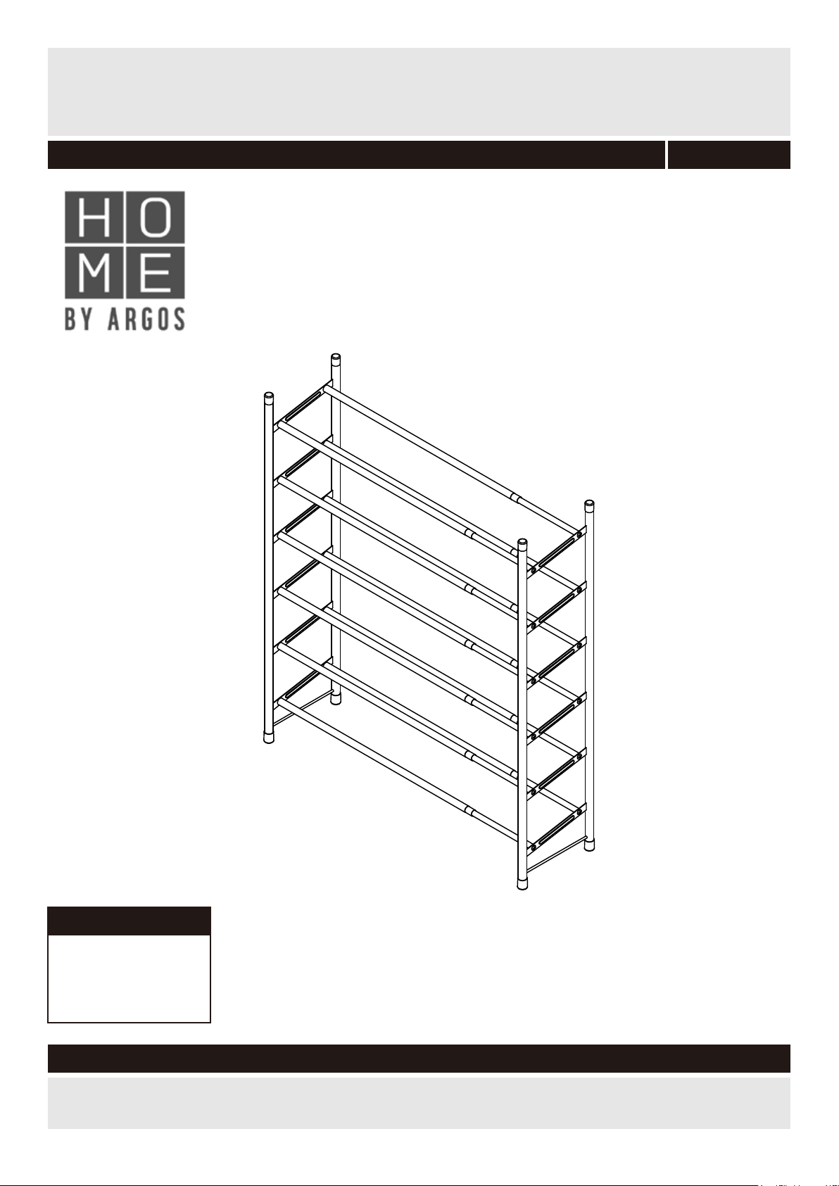
HM 6 TIER EXTENDABLE SHOE RACK CHROME
Assembly Instructions -
Please keep for future reference
607/7446
Dimensions
Width - 62.5-118.5cm
Depth - 22.5cm
Height - 78-100cm
Important – Please read these instructions fully before starting assembly
If you need help or have damaged or missing parts, call the Customer Helpline: 03456 400800
Issue 1 - 10/11/16
Page 2
Safety and Care Advice
Important – Please read these instructions fully before starting assembly
• Check you have all the
components and tools listed on
the following pages.
• Remove all fittings from the
plastic bags and separate them
into their groups.
• Keep children and animals
away from the work area, small
parts could choke if swallowed.
• Make sure you have enough
space to layout the parts before
starting.
Care and maintenance
• Only clean using a damp cloth
and mild detergent, do no use
bleach or abrasive cleaners.
• During assembly do not stand
or put weight on the product,
this could cause damage.
• Assemble the item as close
to its final position (in the same
room) as possible.
• Assemble on a soft level
surface to avoid damaging the
unit or your floor.
• Parts of the assembly will be
easier with 2 people.
• From time to time check that
there are no loose screws on
this unit.
• To reduce
the likelihood of
damaging your
product please
ensure that your
power drill is set on a low torque
setting.
• This product should not be
discarded with household waste.
Take to your local authority
waste disposal centre.
Handy Hints
• Assemble all parts and bolts
loosely during assembly, only
once the product is complete
should you fully tighten the bolts
• Regularly check and ensure
that all bolts and fittings are
tightened properly.
No t e: If required the nex t
page can be cut out and used
as reference thro ugho ut the
assembly. Keep this pag e with
these instructions fo r futu re
reference.
1
Page 3
Components - Parts
If you have damaged or missing components,
call the Customer Helpline: 03456 400800
Please check you have all the fittings listed below
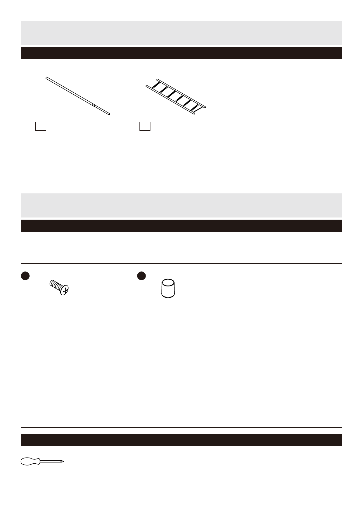
Steel Tube x 12
1
Side Frame x 2
2
Components - Fittings
Please check you have all the fittings listed below
Note: The quantities below are the correct amount to complete the assembly. In some cases more
fittings may be supplied than are required.
A
B
Screw x 24
Tools required
Screwdriver
Rubber End Cap x 8
2
Page 4
Assembly Instructions
Step 1
Assemble the Unit
B
A
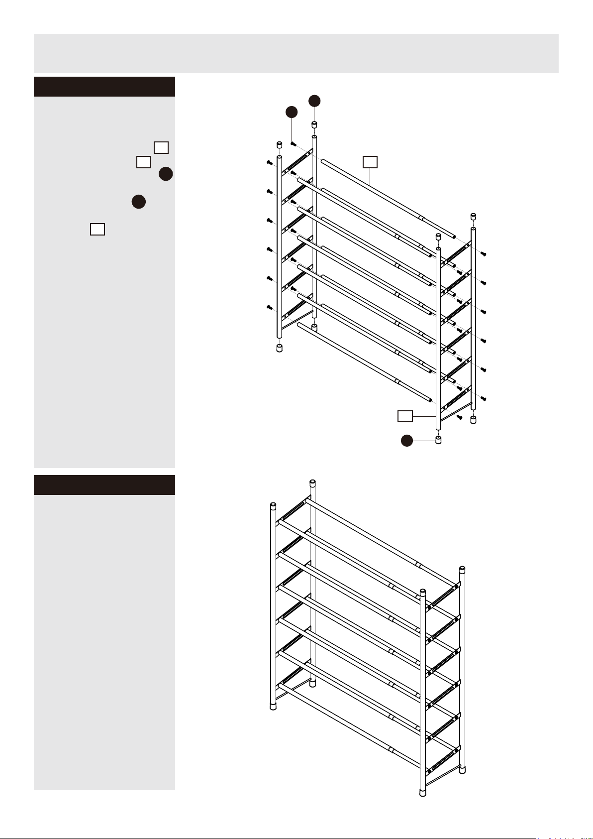
1. Connect Steel Tube
with Side Frame
together using Screw .
2. Insert End Cap to
Top and Bottom Side
Frame .
see fig.1
2
1
2
A
B
1
2
Step 2
The unit is complete
see fig.2
Important Note:
The maximun load for
each tier is 4 kg.
Please do not put any
heavier object than 4 kg
on each tier.
B
fig. 1
fig. 2
3
 Loading...