

Page 1
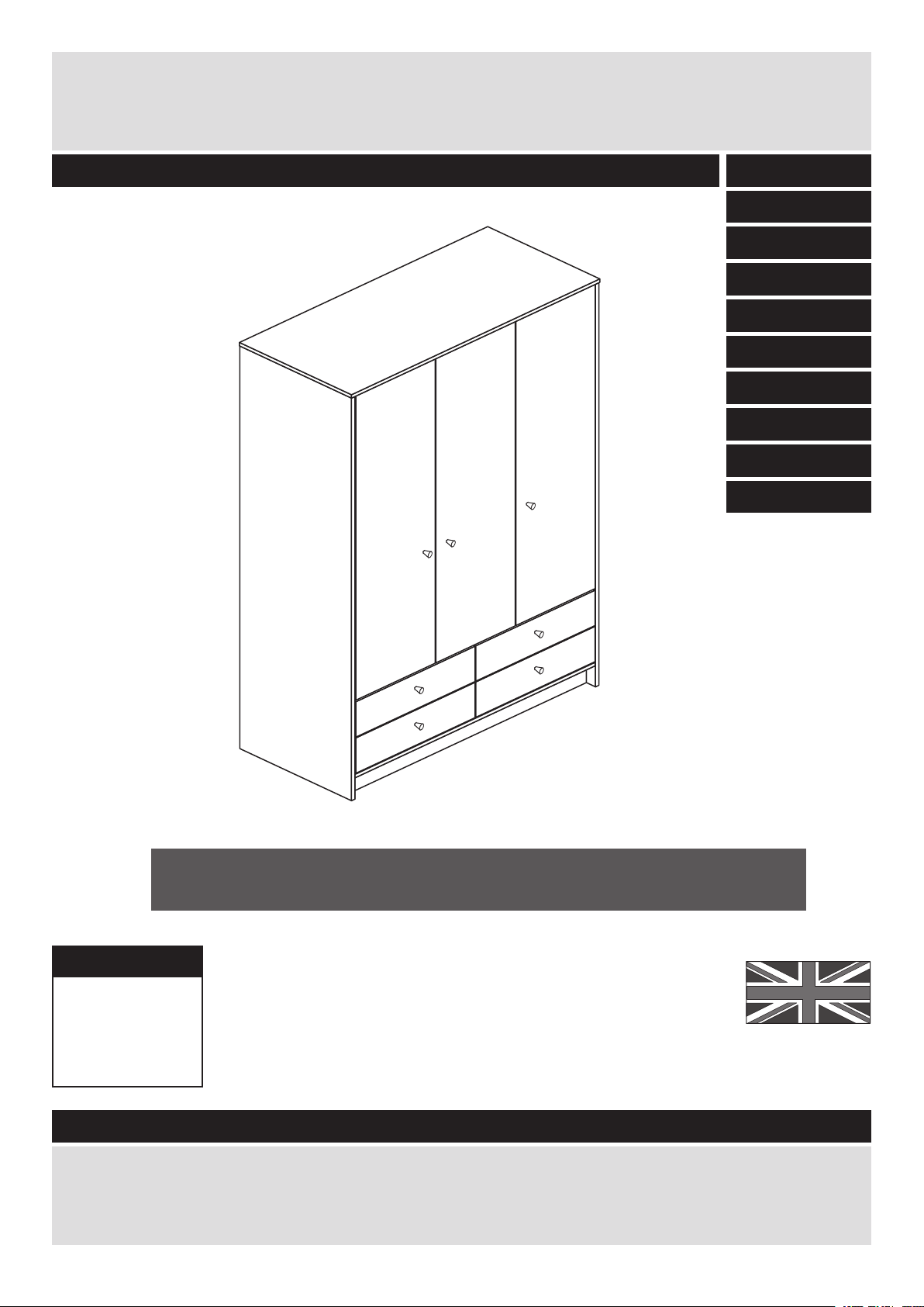
Adult Malibu - 4 Drawer 3 Door Robe
Assembly Instructions - Please keep for future reference
532/8038
563/6307
544/3985
563/7038
544/3930
564/9581
548/2458
565/5429
542/1639
558/2255
More help is available throughout this booklet by scanning
in the QR codes or typing in the links
Dimensions
Width - 110.4cm
Depth - 49.8cm
Height - 180.5cm
Important - Please read these instructions fully before starting assembly
If you need help or have damaged or missing parts, please visit www.argos-support.co.uk
or email: Help@ClickSpares.co.uk (quoting your original order number)
Alternatively, call the Spares Helpline on: 0370 112 1928.
For any other queries please contact the Customer Helpline on: 0345 640 2020
MADE IN
BRITAIN
Issue 1 - 02/06/16
Page 2

Safety and Care Advice
Important - Please read these instructions fully before starting assembly
• Warning: This unit weighs
approximately 83kgs.
Please lift with care.
• Check you have all the
components and tools listed on
pages 2 to 5.
• Remove all fittings from the
plastic bags and separate them
into their groups.
• Keep children and animals
away from the work area, small
parts could choke if swallowed.
• Parts of the assembly will be
easier with 2 people.
Care and maintenance
• Make sure you have enough
space to layout the parts before
starting.
• Do not stand or put weight on
the product, this could cause
damage.
• Assemble the item as close to
its final position (in the same
room) as possible.
• Assemble on a soft level
surface to avoid damaging the
unit or your floor (use opened
out unit carton).
• We do not
recommend the
use of power
drill/drivers for
inserting screws,
as this could damage the unit.
Only use hand screwdrivers.
• Safety note: To prevent
possible overbalancing this unit
must be secured to a wall
using the overbalance protector
kit supplied or, an alternative
fixing method of your choice.
• Dispose of all packaging
carefully and responsibly.
• Only clean using a damp cloth
and mild detergent, do no use
bleach or abrasive cleaners.
• From time to time check that
there are no loose screws on
this unit.
• This product should not be
discarded with household
waste. Take to your local
authority waste disposal centre.
Note: If required the next page
can be cut out and used as
reference throughout the
assembly. Keep this page with
these instructions for future
reference.
1
Page 3
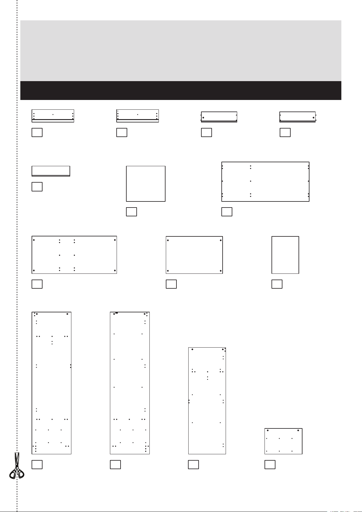
Components - Panels
If you need help or have damaged or missing parts, please visit www.argos-support.co.uk
or email: Help@ClickSpares.co.uk (quoting your original order number)
Alternatively, call the Spares Helpline on: 0370 112 1928.
For any other queries please contact the Customer Helpline on: 0345 640 2020
Please check you have all the panels listed below
1 2Left Drawer
(DF7359)
Front
(53 x 15.7cm)
Drawer Back
5
(47.8 x 13cm)
x 2
(W478-130)
x 4
Right Drawer
Front
(DF7362)
(53 x 15.7cm)
Drawer Base
6 Top
(48.9 x 44.7cm)
x 2
(T489-447)
x 4
When applicable, remove any
protective film before use
3 Left Drawer
Side
(WB450-130LH)
(45 x 13cm)
x 4
7
(110.35 x 49.8cm)
(DF7347)
4
Right Drawer
Side
(45 x 13cm)
(WB450-130RH)
x 4
8
Horizontal
(106.95 x 47.4cm)
(DF7351)
9
Wide Shelf (DF7363)
(71.4 x 47cm)
10
Loose Shelf (DF7364)
(34.05 x 47cm)
x 3
11 Right Side
(179 x 49.6cm)
(DF7348)
12 Divider
(179 x 49.6cm)
(DF7349)
13
(134.4 x 47.2cm)
(DF7350)
14Left Side
Drawer Divider
(32.35 x 47.2cm)
(DF7352)
2
Page 4
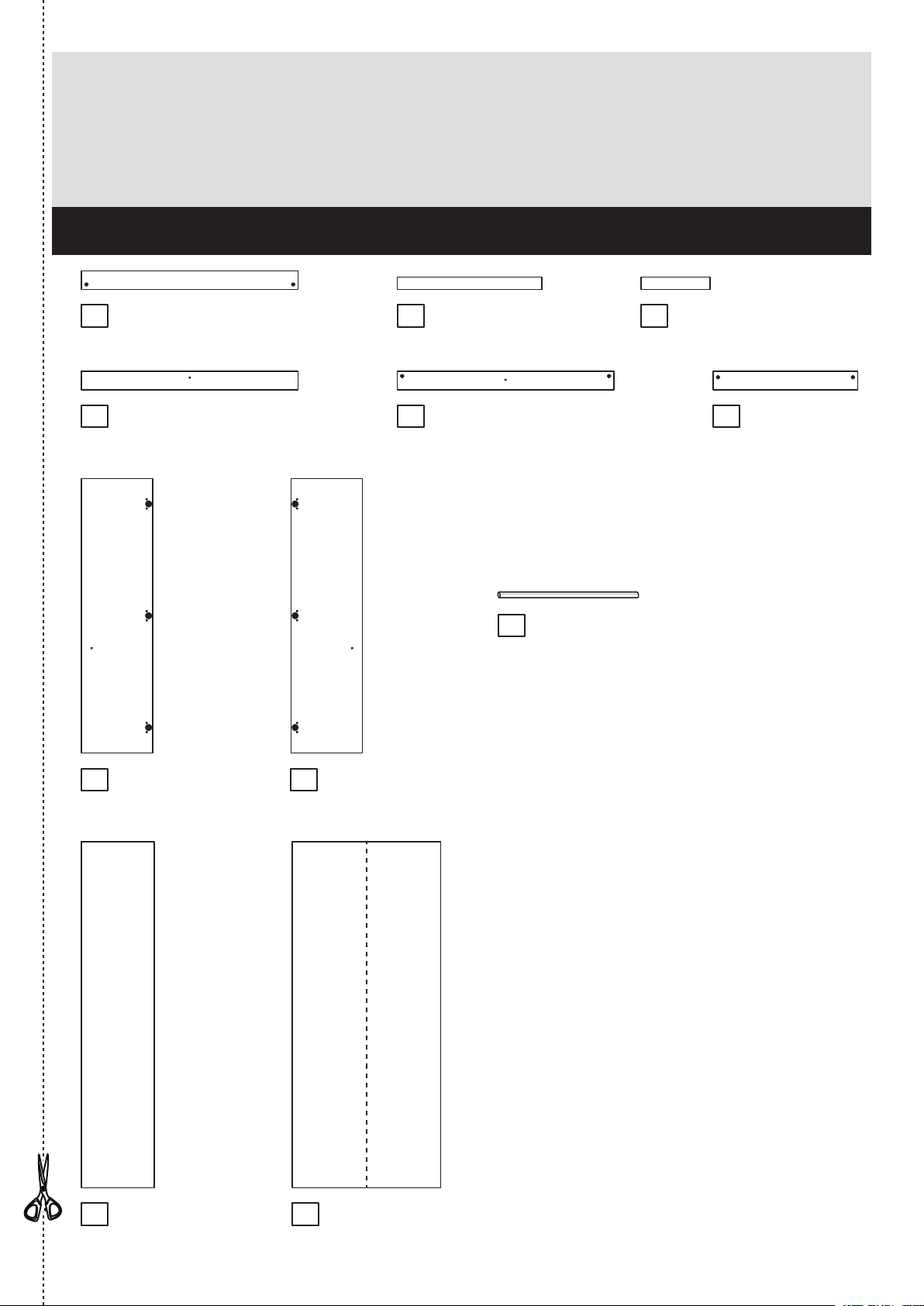
Components - Panels
If you need help or have damaged or missing parts, please visit www.argos-support.co.uk
or email: Help@ClickSpares.co.uk (quoting your original order number)
Alternatively, call the Spares Helpline on: 0370 112 1928.
For any other queries please contact the Customer Helpline on: 0345 640 2020
Please check you have all the panels listed below
15 Plinth
(DF7353)
(106.95 x 9.2cm)
18 Front Cross Rail
(106.95 x 9.2cm)
(DF7354)
16 Large Top Rail
(71.4 x 6cm)
19 Back Cross Rail
(106.95 x 9.2cm)
23
When applicable, remove any
protective film before use
(DF5858)
(DF7355)
Long Hanging Rail (FHR708)
(70.8cm long)
17 Small Top Rail
(34.05 x 6cm)
(DF7356)
20 Back Rail
(71.4 x 9.2cm)
(DF5866)
21 Left Door
(135.6 x 35.25cm)
24 Small Back
(170.9 x 36cm)
3
(DF7357)
(X1709-360)
x 2
22 Right Door and Middle Door
(135.6 x 35.25cm)
25 Large Back
(170.9 x 73.3cm)
x 2
(X1709-733)
(DF7357)
Page 5
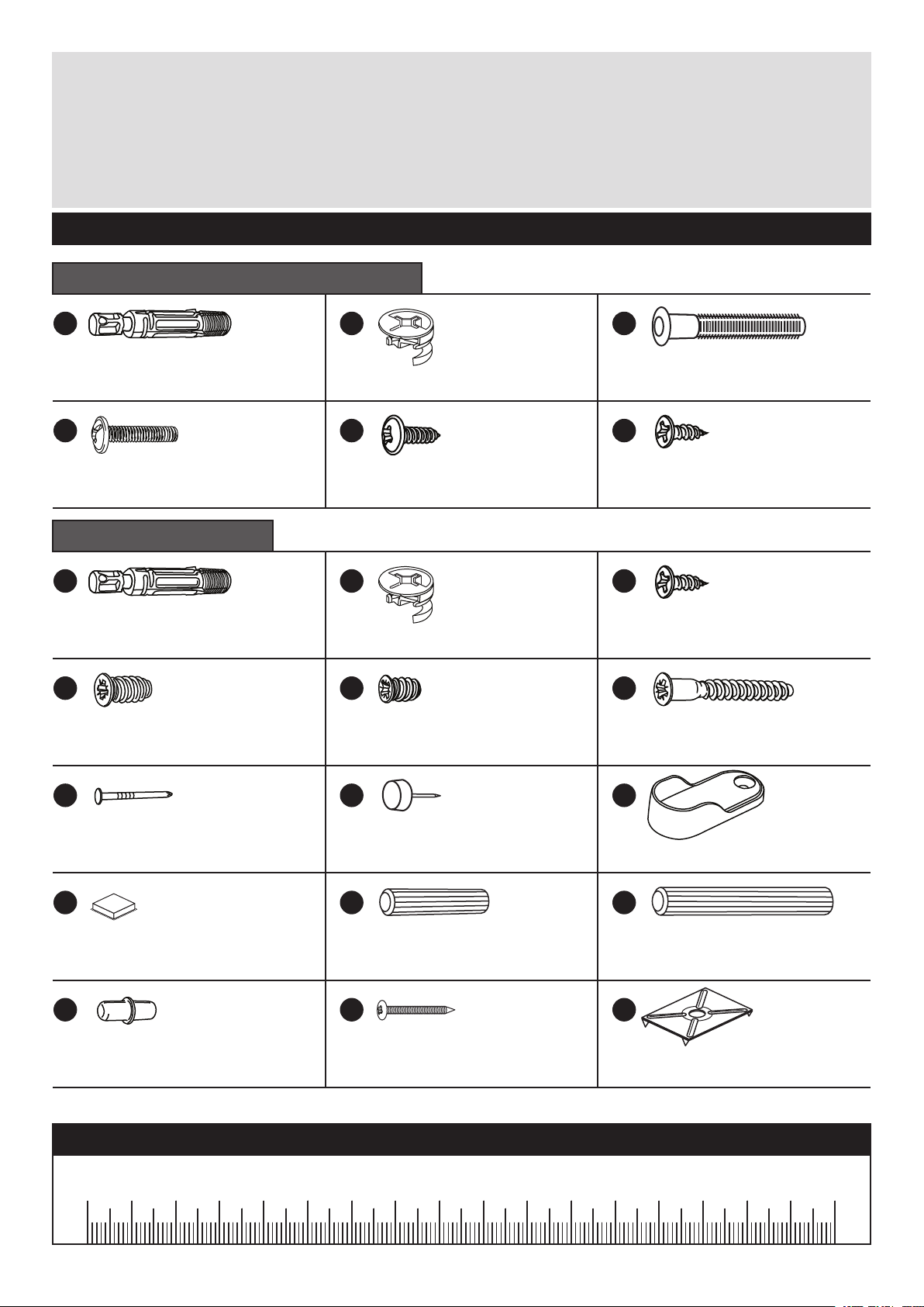
Components - Fittings
If you need help or have damaged or missing parts, please visit www.argos-support.co.uk
or email: Help@ClickSpares.co.uk (quoting your original order number)
Alternatively, call the Spares Helpline on: 0370 112 1928.
For any other queries please contact the Customer Helpline on: 0345 640 2020
Please check you have all the fittings listed below
Drawer Fittings Bag marked ‘drw kit’
A
Quickfit dowel
D E
19mm
Screw (F461) x 7
(F545) x 8
Main Fittings Bag
A
Quickfit dowel
G
13mm Screw (F52) x 4
(F545) x 22
B
Large locking cam nut (F607) x 8
13mm Screw (F79) x 8
B
Large locking cam nut (F607) x 22
9mm Screw (F73) x 24
C
Knock-in Peg
F
13mm Screw (F63) x 16
F
13mm Screw
IH
40mm Screw
(F171GY) x 16
(F63) x 8
(F910) x 4
J
Nail (F51) x 35
M
Door Buffer (F137) x 6
P
Shelf stud (F110) x 12
K
Plastic Nail (F91) x 6
N
Wooden dowel (F22) x 41
Q
Nail screw
(F277) x 5
L
Rail Holder (F891) x 2
O
Large wooden dowel
R
Back holder (F276) x 5
(F40) x 2
Ruler - Use this ruler to help correctly identify the screws
mm 10 20 30 40 50 60 70 80 90 100 110 120 130 140 150 160 170
4
Page 6
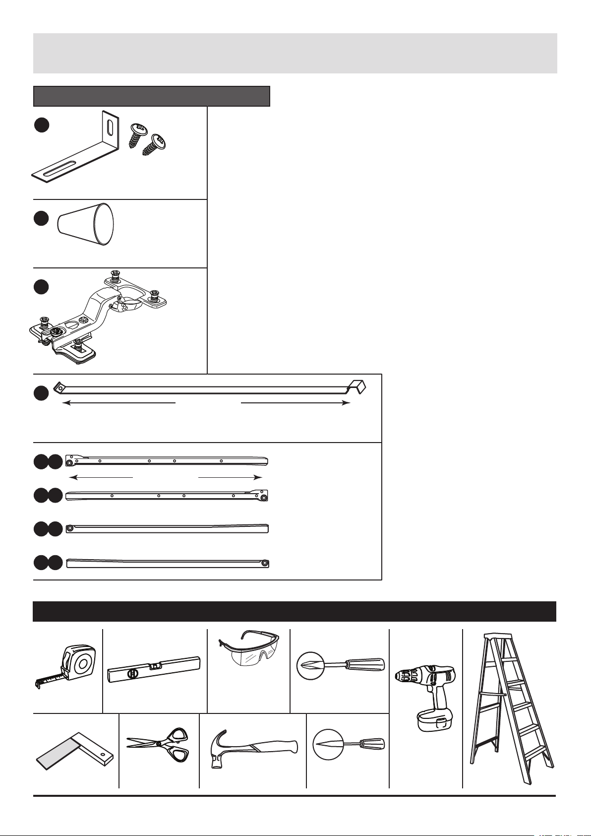
Components - Fittings
Individual Fittings Bags
S
Overbalance protector
F474) x 1
kit (
T
Handle
(F418) x 7
U
Pre-mounted
hinge (
V
Drawer Brace (F427) x 4
M
W
W
W
a
b
c
CL
DL
F419) x 9
436mm long
450mm long
CL Runner
CR
CR Runner
DL Runner
(F608) x 4
(F609) x 4
(F610) x 4
d
W
Tools required
Rule
Rule
5
Spirit
level
ScissorsSquare
DR
DR Runner
Eye protection
(when using a
hammer or drill)
Cross-head
screwdriver
Hammer Bradawl
(F611) x 4
Electric drill
(only use
when drilling
into walls)
Step
ladder
Page 7
Assembly Instructions
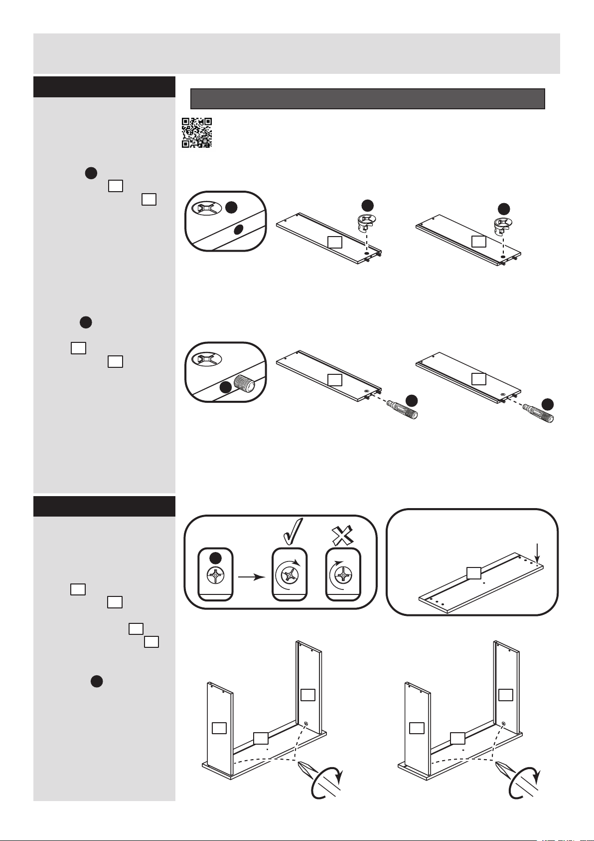
Step 1
Use the Drawer Fittings Bag marked ‘drw kit’ for Steps 1 - 7
Prepare the 4 pair of
drawer sides
a: Insert a large locking
cam nut into the 4 left
drawer sides and the
4 right drawer sides .
Note: The arrow on the
locking cam nut must
point towards the
hole in the end of the
panel.
B
3
4
b: Push 1 of the quickfit
dowels as far as it will
go into the left drawer
sides and the right
drawer sides .
Note: Only the plastic
thread of the quickfit
dowel sticks out from the
panel.
A
3
4
Standard Drawer Box Assembly
hps://www.youtube.com/watch?v=HclfJdkm-Lg
a:
B
3
B
x 4 x 4
b:
A
3
A
x 4 x 4
B
4
4
A
Step 2
Fit the drawer sides
to the 4 drawer fronts
Push the left drawer
sides . and right
drawer sides . down
onto the back of the 2
left drawer fronts and
2 right drawer fronts .
Turn the large locking
cam nuts clockwise
as far as they will go to
secure the panels.
Important: Make sure
there is no gap between
the fitted panels.
3
4
1
2
B
B
x 2
3
11
Note: The 2 right drawer fronts
have a small identification hole
(see panels page).
x 2
4
3
1 2
11
2
4
6
Page 8
Assembly Instructions
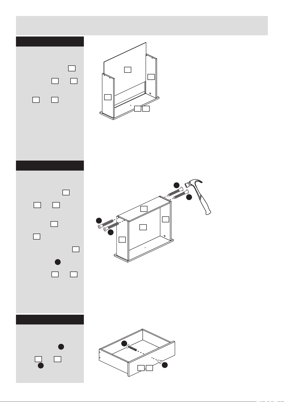
Step 3
Fit the drawer bases
Slide a drawer base
down the grooves in the
drawer sides and
and down into the
groove in the drawer
front and .
1 2
6
43
Step 4
Fit the drawer backs
Fit a drawer back
between the drawer
sides and .
3 4
5
6
4
x 4
3
1 2
C
x 4
C
5
Make sure that the
drawer base fits into
the groove in the drawer
back .
Hold the drawer back
in position and tap the
knock-in pegs
through the holes in the
drawer sides and .
5
6
5
C
3 4
Step 5
Fit the handles
Attach a handle to
each of the 4 drawer
fronts and using
screws .
1 2
D
T
C
C
x 4
4
6
3
Important: You will need
3 more of these screws
D
1 2
T
from the drawer fittings
bag to fit the handles to
the doors at a later step.
7
Page 9
Assembly Instructions
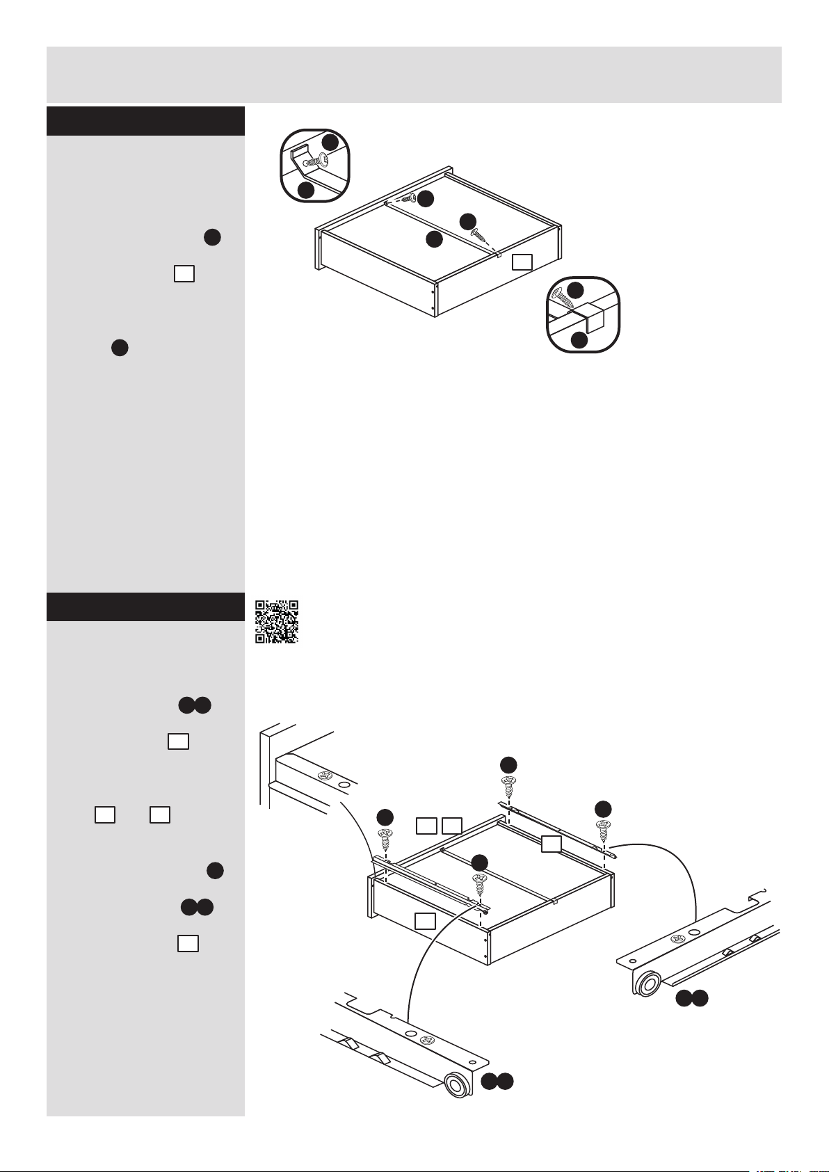
Step 6
E
Fit the drawer braces
Turn the 4 drawer
assemblies over and
hook a drawer brace
onto the bottom edge of
the drawer back .
Fix it to the drawer front
and drawer back using 2
screws .
E
V
5
V
Important: Make sure
that the drawer assembly
is square before fitting
the drawer brace.
x 4
E
E
V
5
E
V
Step 7
Fit runners to the
drawers
Fit the DL runner to
the bottom edge of the
left drawer side , as
shown, making sure that
it is pushed up against
the back of the drawer
front and . Use a
bradawl to mark the
fixing positions, then
secure with 2 screws .
Fit the DR runner to
the bottom edge of the
right drawer side
using the same method.
1 2
W c
3
F
W d
4
Fixing Bottom Mounter Runners
hps://www.youtube.com/watch?v=Z6lGMy19h7Q
Runners must be
pushed up against
the drawer front
DL
F
F
21
F
DL
3
x 4
4
F
DR
W d
W c
8
Page 10

Assembly Instructions
Step 8
Prepare the divider
Fit a rail holder to the
divider using 2
screws .
13
G
Insert 2 large locking
cam nuts into the
divider .
13
Push 2 of the quickfit
dowels as far as they
A
will go into the divider .
Tap 6 wooden dowels
into the divider .
Note: Wooden dowels
must not stick out from
the edge by more than
10mm or they may
damage other panels.
L
B
13
N
13
Use the Main Fittings Bag for Steps 8 - end
A
B
B
A
G
G
L
13
Finished
front edge
N
N
N
N
B
N
10mm
N
A
N
Step 9
Prepare the horizontal
Insert 4 large locking
cam nuts into the
horizontal .
Push 4 of the quickfit
dowels as far as they
will go into the horizontal
. .
8
Tap 6 wooden dowels
into the horizontal .
B
8
A
N
8
B
A
N
N
N
A
B
front edge
Finished
B
8
B
A
N
N
N
A
9
Page 11

Assembly Instructions
Step 10
Fit the base
Push the horizontal
onto the divider and
fit it using 2 screws .
8
13
I
Note: To make the
assembly easier, place
polystyrene blocks from
the packaging underneath
the panels to raise the
assembly.
Step 11
Prepare the wide
shelf
Insert 4 large locking
cam nuts into the
wide shelf .
Push 4 of the quickfit
dowels as far as they
will go into the wide shelf
9
. .
Tap 6 wooden dowels
into the wide shelf .
B
9
A
N
9
13
Finished
front edge
I
I
N
A
Polystyrene
block
N
N
B
Finished
front edge
A
8
Finished
front edge
B
9
B
Polystyrene
block
B
N
A
A
N
N
Step 12
Fit the wide shelf
Push the wide shelf onto
the divider .
13
Turn the 2 large locking
cam nuts fited to the
wide shelf clockwise
B
9
as far as they will go to
secure the panels.
Important: Make
sure there is no gap
between the fitted
panels.
9
Carcase Assembly
hps://www.youtube.com/watch?v=9C7tgv5xnbE
B
13
9
Finished
front edge
10
Page 12

Assembly Instructions
Step 13
Prepare the drawer
divider
a: Fit 2 CL runners
to the drawer divider .
The 1st screw uses
the 1st hole in from the
front of the runner.
The 2nd and 3rd screws
. use the holes that line
H
up with the other panel
holes.
b: Fit a screw into
the hole at the top of the
runner .
W a
c: Insert 2 large locking
cam nuts into the
drawer divider .
B
W a
14
H
F
14
hps://www.youtube.com/watch?v=Z6lGMy19h7Q
front edge
Finished
Finished
front edge
a:
Finished
front edge
c:
Fixing Bottom Mounter Runners
1st
H
screw
W a
CL
H
H
CL
CL
H
14
H
CL
CL
H
H
W a
W a
B
A
N
B
N
Finished
front edge
N
A
front edge
Finished
b:
F
W a
F
F
CL
CL
14
Push 2 of the quickfit
dowels as far as they
A
will go into the drawer
divider .
Tap 3 wooden dowels
into the drawer divider .
14
N
14
Turn the drawer
divider over
d: Fit 2 CR runners
to the drawer divider .
The 1st screw uses
the 1st hole in from the
front of the runner.
The 2nd and 3rd screws
H
. use the holes that line
up with the other panel
holes.
e: Fit a screw into
the hole at the top of the
runner .
W b
W b
14
H
F
14
Turn the drawer divider over
1st
screw
W b
CR
H
d: e:
14 14
H
H
H
H
H
H
CR
CR
W b
W b
front edge
Finished
Finished
front edge
F
front edge
Finished
F
F
CR
CR
Finished
front edge
11
Page 13

Assembly Instructions
Step 14
Fit the drawer divider
Push the drawer divider
. onto the horizontal .
14 8
Turn the 2 large locking
cam nuts fitted to the
drawer divider
clockwise as far as they
will go to secure the
panels.
B
9
14
8
Important: Make
sure there is no gap
between the fitted
panels.
Step 15
Prepare the large top
rail
Tap 2 wooden dowels
into the large top rail .
N
16
Finished
front edge
16
Finished
front edge
N
N
Step 16
Fit the large top rail
Push the large top rail
up against the divider .
Tap 2 large wooden
dowels through the
divider and into the
large top rail until
O
13
16
they ‘’bottom out’’.
16
13
O
O
13
16
Finished
front edge
12
Page 14

Assembly Instructions
Step 17
1st
Prepare the right side
a: Fit 2 CR runners
to the right side .
W b
12
CR
screw
W b
G
front edge
Finished
The 1st screw uses
H
the 1st hole in from the
front of the runner.
The 2nd and 3rd screws
. use the holes that line
H
up with the other panel
holes.
b: Fit a screw into
F
the hole at the top of the
runner .
W b
Insert 2 large locking
cam nuts into the
right side .
B
12
Push 2 of the quickfit
dowels as far as they
A
will go into the right side
.
12
H
F
H
H
H
CR
CR
W b
front edge
Finished
H
W b
H
12
Finished
front edge
B
A
N
B
N
N
A
Tap 3 wooden dowels
into the right side .
N
12
Step 18
Prepare the small top
rail
Tap 2 wooden dowels
into the small top rail .
N
17
N
N
Finished
front edge
12
F
F
CR
CR
17
Finished
front edge
13
Page 15

Assembly Instructions
Step 19
Fit the small top rail
to the right side
Finished
front edge
17
Push the small top rail
17
down onto the right side
. .
12
Step 20
Fit the right side
Push the right side
onto the horizontal .
Make sure that the small
top rail is pushed
17
onto the 2 large wooden
dowels fitted through
the divider .
O
13
Turn the 2 large locking
cam nuts fitted to the
horizontal clockwise
B
8
as far as they will go to
secure the panels.
Important: Make
sure there is no gap
between the fitted
panels.
12
8
Finished
front edge
12
Finished
CR
CR
12
8
front edge
17
13
Step 21
Prepare the back
cross rail
Insert 2 large locking
cam nuts into the
back cross rail .
Push 2 of the quickfit
dowels as far as they
will go into the back
cross rail .
Tap 2 wooden dowels
into the back cross rail .
B
19
A
19
N
9
B
N
A
19
B
N
A
14
Page 16

Assembly Instructions
Step 22
Fit the back cross rail
Push the back cross rail
. onto the right side .
19 12
Turn the large locking
cam nut fitted to the
back cross rail
B
19
clockwise as far as it will
go to secure the panels.
Important:
Make sure there
is no gap between
the fitted panels.
Secure the cross back
rail to the drawer
19
divider using screw .
14
I
Step 23
Prepare the front
cross rail
Tap 4 wooden dowels
into the front cross rail .
N
18
12
19
I
N
N
14
18
Finished
front edge
Step 24
Fit the front cross rail
Push the front cross rail
. onto the right side .
18 12
Secure the front cross
rail to the drawer
18
divider using screw .
14
I
N
N
12
14
18
I
Finished
front edge
15
Page 17

Assembly Instructions
Step 25
Prepare the plinth
Insert 2 large locking
cam nuts into the
plinth .
B
15
Push 2 of the quickfit
dowels as far as they
will go into the plinth .
Tap 2 wooden dowels
into the plinth .
A
15
N
15
Step 26
Fit the plinth
B
A
N
B
15
A
N
Push the plinth onto
the right side .
15
12
Turn the large locking
cam nut fitted to the
plinth clockwise as
B
15
far as it will go to secure
the panels.
Important: Make sure
there is no gap between
the fitted panels.
Step 27
Prepare the back rail
Insert 2 large locking
cam nuts into the
back rail .
Push 2 of the quickfit
dowels as far as they
will go into the back rail
. .
20
B
20
A
12
15
B
N
A
Finished
front edge
20
B
Tap 2 wooden dowels
into the back rail .
20
N
N
A
16
Page 18

Assembly Instructions
Step 28
1st
H
screw
Prepare the left side
a: Fit 2 CL runners
to the left side .
W a
11
front edge
Finished
W a
CL
The 1st screw uses
H
the 1st hole in from the
front of the runner.
The 2nd and 3rd screws
H
. use the holes that line
up with the other panel
holes.
b: Fit a screw into
F
the hole at the top of the
runner .
W a
c: Insert 2 large locking
cam nuts into the left
side .
Push 2 of the quickfit
dowels as far as they
will go into the left side
. ..
11
Tap 3 wooden dowels
into the left side .
Fit a rail holder to the
left side using 2
screws .
B
11
A
N
11
L
11
G
a:
front edge
Finished
b:
Finished
front edge
H
H
CL
F
H
W a
H
CL
H
H
W a
W a
11
Finished
front edge
F
F
CL
CL
11
17
c:
B
A
G
G
N
B
N
N
A
Finished
front edge
11
CL
CL
L
Page 19

Assembly Instructions
Step 29
Fit the back rail
Push the back rail
onto the divider .
Turn the large locking
cam nut fitted to the
back rail clockwise
as far as it will go to
secure the panels.
Important: Make sure
there is no gap between
the fitted panels.
B
20
20
13
20
13
Note: Support the
back rail until the left
side has been fitted
in the next step.
Step 30
Fit the left side
Push the left side
onto the assembly.
Turn the 7 large locking
cam nuts clockwise
as far as it will go to
secure the panels.
Important: Make sure
there is no gap between
the fitted panels.
B
11
11
Finished
front edge
18
Page 20

Assembly Instructions
Step 31
Fit the top
Push the top onto
7
the assembly.
Turn the 6 large locking
cam nuts clockwise
B
as far as it will go to
secure the panels.
Important: Make sure
there is no gap between
the fitted panels.
7
Step 32
Fit the 6 plastic nails
Tap 2 plastic nails
into the bottom edge of
each side and as
11 12
shown.
Tap 2 plastic nails
into the plinth as
shown.
19
K
K
K
K
15
12
K
15
K
K
11
K
Page 21

Assembly Instructions
Step 33
Fit the back panels
a: Square up the unit by
making sure that
measurement x:x equals
y:y.
Place the small back
and the large back
down onto the unit as
shown.
Make sure that the 2
backs are pushed up
tight against each other
and that they meet over
the back edge of the
divider.
b: Nail around
the outside edges
of the 2 backs.
J
24
25
y
y
Squaring up a Robe and tting the Back Panel
www.youtube.com/watch?v=udEKmXmPEW0
The measurement from top corner X to bottom corner X must be
a:
equal to the measurement from top corner Y to bottom corner Y
b:
J
24
x
25
x
Note: Do not
nail where the
backs meet.
y
Note: Do not nail where
the backs meet. Nails
should be spaced out
evenly.
Step 34
Secure the backs
Tap the nail screws
through the back holders
R
. and down between
the backs and
into the back edge
of the divider .
Keep tapping the nail
screws in until the
back holders dig into
the small and large back.
24
13
Q
Q
25
R
24
13
25
25
Q
R
RQ
+
R
x 5
Carefully stand the
unit up for the next
step.
Warning: The
unit is heavy.
Lift with care.
20
Page 22

Assembly Instructions
Step 35
Fit the hanging rail
and the drawers
Push the hanging rail
into the rail holders .
Slide the wheels of the
runners fitted to the
drawers, over the wheels
of the runners fitted to
the side panels and push
the drawers into position.
23
L
Fixing Bottom Mounter Runners
hps://www.youtube.com/watch?v=Z6lGMy19h7Q
23
Side
panel
23
L
Drawer
Step 36
Fit the shelf studs
For each of the 3 loose
shelves , insert 4 shelf
studs into the holes
shown.
10
P
x 4
P
x 4
P
x 4
P
21
Page 23

Assembly Instructions
Step 37
Fit the shelves
Lower the 3 loose
shelves down onto
the shelf studs .
10
P
10
10
10
Step 38
Prepare the 3 doors
Push fit 3 hinges into
the left door , the right
door and the middle
22
22
door .
Secure each hinge by
tightening up its 2
screws.
U
21
Pre-mounted Hinge Fitting & Adjustment
hps://www.youtube.com/watch?v=b4NeCGnpjP8
U
U
U
U
22
U
21
U
x 2
22
Page 24

Assembly Instructions
Step 39
Fit the doors and the
handles
2 people are needed
here
Fit 1 door , and
. at a time, by lining up
the 2 screws in the top
hinge with the 2 holes
at the top of the panel
and push them in.
Tighten the 2 screws on
the hinge.
Fix the bottom hinge
next, followed by the
other hinge.
Attach a handle to
each door using screws
. .
D
212222
U
T
Pre-mounted Hinge Fitting & Adjustment
hps://www.youtube.com/watch?v=b4NeCGnpjP8
Press the screws into
the holes in the panels
U
When the hinges have
been pushed in,
tighten up their screws
U
Note: Fit the
top hinge 1st
21
22
22
T
T
D
T
23
Page 25

Assembly Instructions
Step 40
Adjust the doors if
needed
a: Before adjusting the
doors, use a spirit level
to check the base (or
top) of the unit is level,
front-to-back and
side-to-side in the 3
positions shown.
Use suitable packing
pieces (not supplied) to
make the unit level
BEFORE making any
adjustment to the hinges,
as shown.
b: Height adjustment.
Loosen screws A on
hinge plates and move
door up or down as
required.
Retighten screw A.
Pre-mounted Hinge Fitting & Adjustment
hps://www.youtube.com/watch?v=b4NeCGnpjP8
a:
b:
A
A
c:
c: Forward and Back
adjustment.
Loosen screw B on hinge
plate and move door in
or out as required.
Retighten screw B.
d: Sideways
adjustment.
To move door ‘out’
loosen screw C.
To move door ‘in’ tighten
screw C.
B
d:
C
24
Page 26

Assembly Instructions
Step 41
Fit the door buffers
M
50mm
Stick a door buffer
M
onto the top corner of
each door , and
21 22 22
about 50mm in from the
edge.
Stick a door buffer
M
onto the bottom corner
of each door , and
. about 50mm in from
22
21 22
the edge.
M
22
22
21
M
25
Page 27

Assembly Instructions
Step 42
Fit the overbalance
protector kit
To prevent possible
overbalancing this unit
must be secured to a
suitable wall by fitting of
the overbalance
protector kit to the
unit, or an alternative
fixing method of your
choice.
Wall fixings are not
supplied as they will
need to suit the wall
type.
S
S
S
Take care when
Note:
drilling the wall that you
do not drill into any
pipes, wires etc.
If in doubt, consult an
expert.
Assembly is complete
If you need help or have damaged or missing parts, please visit www.argos-support.co.uk
or email: Help@ClickSpares.co.uk (quoting your original order number)
Alternatively, call the Spares Helpline on: 0370 112 1928.
For any other queries please contact the Customer Helpline on: 0345 640 2020
26
Page 28

ALR3321
 Loading...