

Page 1
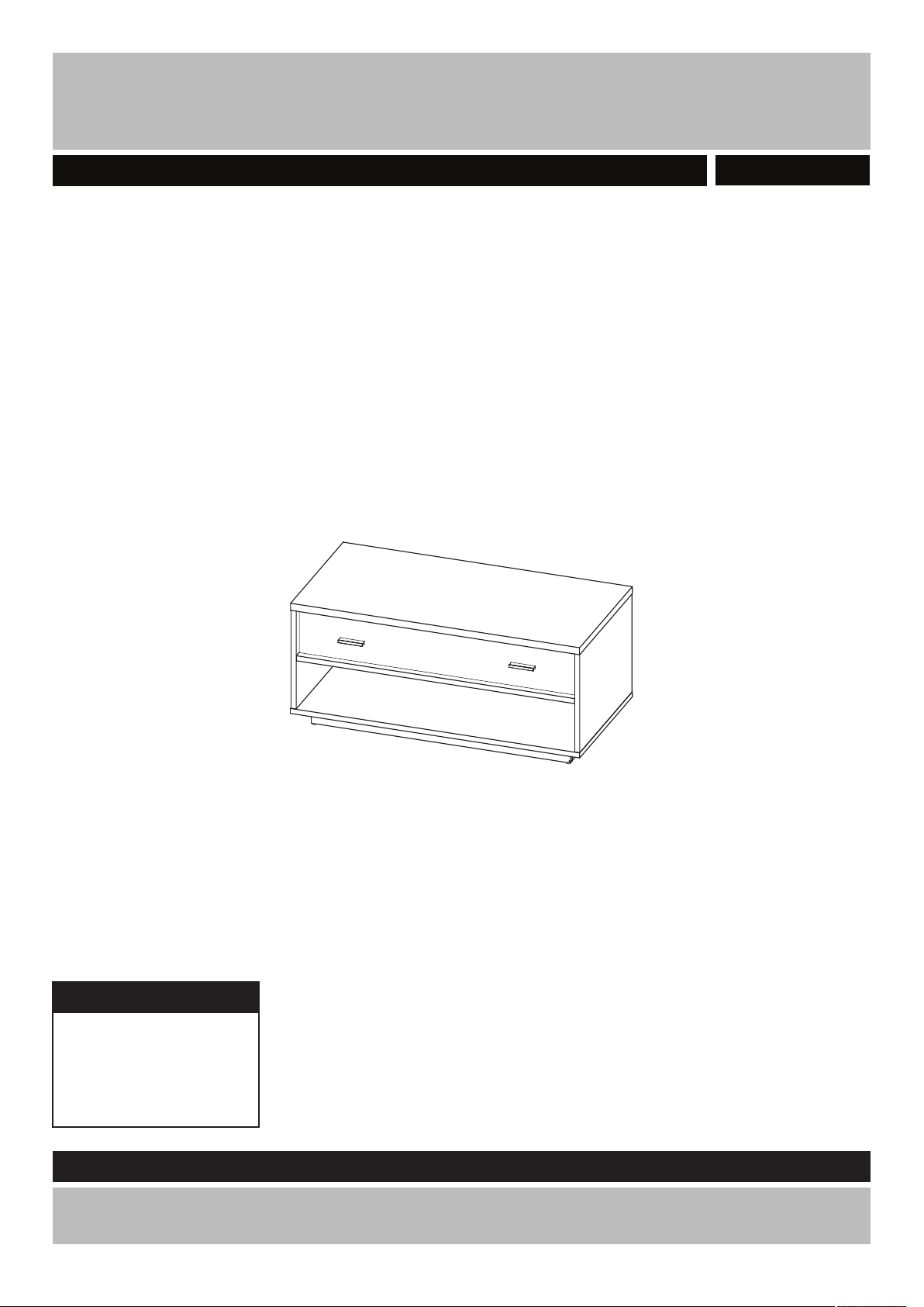
Darcy - Coffee Table/TV Stand
Assembly Instructions - Please keep for future reference
425/8827
Dimensions
Width - 100 cm
Depth - 50 cm
Height - 45 cm
Important - Please read these instructions fully before starting assembly
If you need help or have damaged or missing parts, call the Customer Helpline: 0845 6400 800
Issue 1 - 03/06/2015 1
Page 2
!
Safety and Care Advice
Important - Please read these instructions fully before starting assemb ly
• Check you have all the
components and tools listed on
pages 3 and 4.
• Remove all fittings from the
plastic bags and separate them
into their groups.
• Keep children and animals
away from the work area, small
parts could choke if swallowed.
• Make sure you have enough
space to layout the parts before
starting.
• Do not stand or put weight
on the panels during assembly,
this could cause damage.
• Assemble the unit as close
to its final position (in the same
room) as possible.
• Assemble on a soft level
surface to avoid damaging the
unit or your floor.
• Parts of the assembly will be
easier with 2 people.
• If using power tools, please
follow the safety instructions
supplied with the tools.
• We do not
recommend the
use of power drill/
drivers for inserting
screws, as this
could damage the unit. Only use
hand screwdrivers.
• Dispose of all packaging
carefully and responsibly.
• Warning: The unit weighs
approximately 29 kgs.
Please lift with care.
Care and maintenance
• Only clean using a damp cloth
and mild detergent, do no use
bleach or abrasive cleaners.
2
• From time to time check that
there are no loose screws on
this unit.
• This product should not be
discarded with household
waste. Take to your local
authority waste disposal centre.
Note: if required the next
page can be cut out and used
as reference throughout the
assembly .Keep this page with
these instructions for future
reference.
Page 3
If you have damaged or missing components
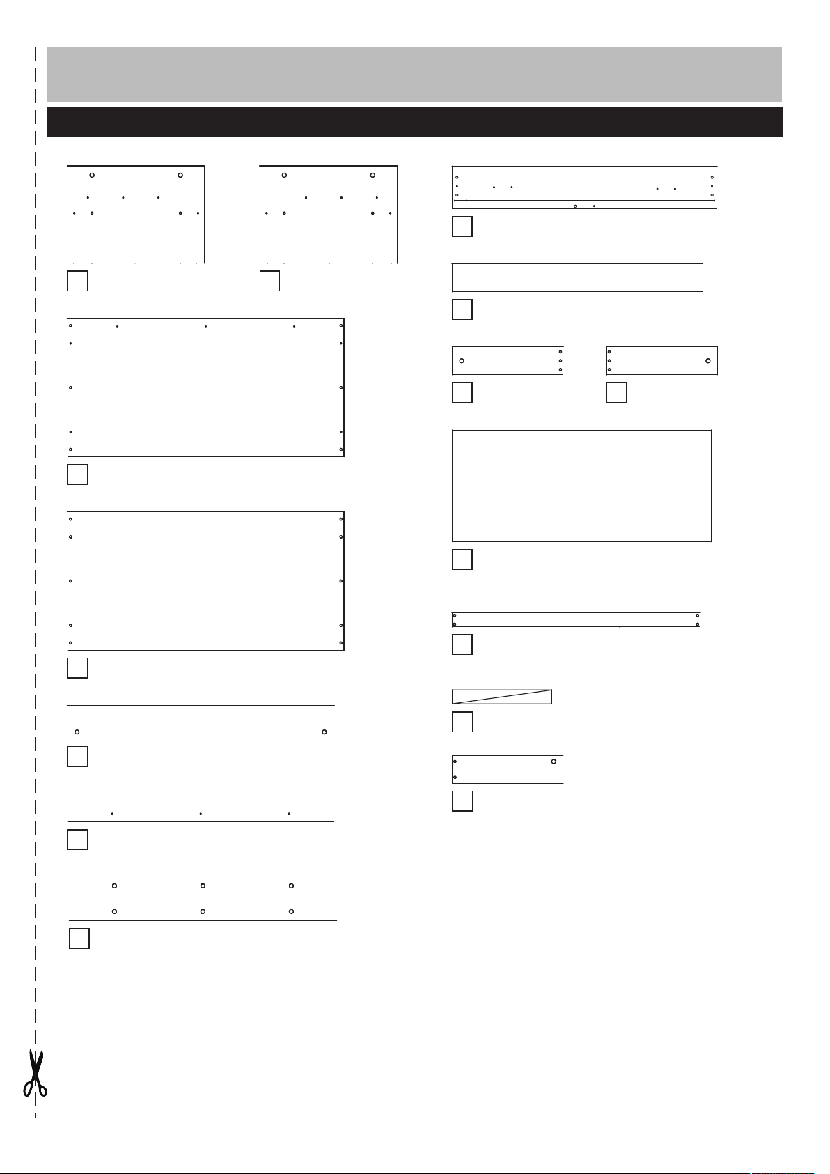
Component - Panels
call the Customer Helpline: 0845 6400 800
Please check you have all the panels listed below
Drawer front
8
(95.7 x 15.2cm)
Left side
1
(35.2 x 49.6cm)
Top
3
(100 x 50.0cm)
Bottom
4
(100 x 50cm)
Right side
2
(35.2 x 49.6cm)
Drawer back
9
(90.7 x 10cm)
Drawer left side
10
(40 x 10cm)
Drawer base
12
(93.8 x 40,5cm)
Long plinth x 2
13
(89.6 x 5cm)
Drawer right side
11
(40 x 10cm)
Front support
5
(96.3 x 12cm)
Back support
6
(96.3 x 12cm)
Back
7
(96.3 x 16.1cm)
Short plinth x 2
14
(36 x 5cm)
Drawer support
15
(40 x 10cm)
3
Page 4
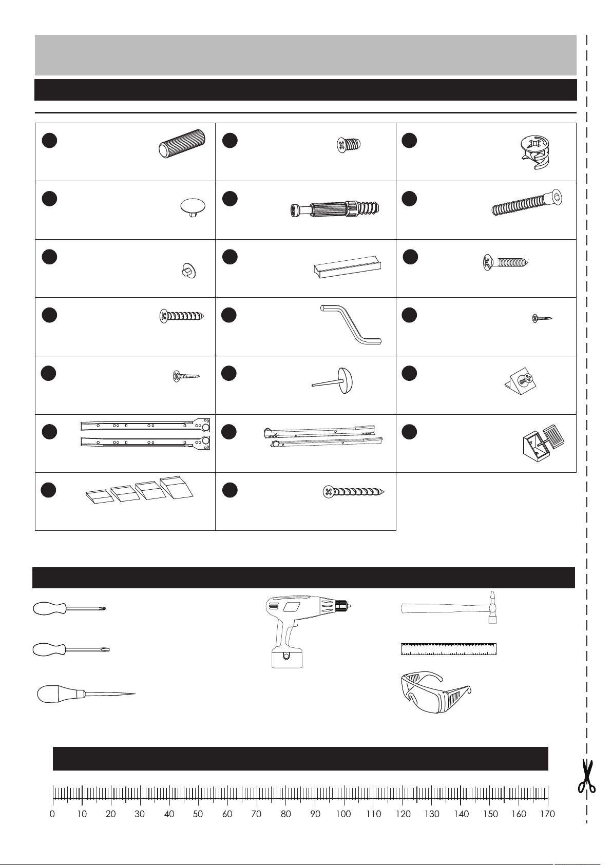
Components - Fittings
Please check you have all the fittings listed below
A
Wooden dowel x 41 (8x35)
Cap x 17
G
Cap x 6
J
3x20mm Screw x 6
M
3,5x16mm Screw x 12
P
B
5x13mm Screw x 6
ED
Metal dowel x 17
H
Handle x 2
K
Allen key x 1
N
Feet x 4
Q
C
( 15x13)
F
Locking nut x 17
(7x50) Hexagon bolt x 6
HI
3.5x27mm Screw x 4
L
3x16mm Screw x 9
O
Stabilizer x 2
R
Runner x 1
S
Height adjuster x 1
Tools required
Phillips screwdriver
(medium & large)
Flatblade screwdriver
(medium)
Punch
Runner x 1
T
4x40mm Screw x 2
Drill
Mounting bracket x 6
0 10 20 30 40 50 60 70 80 90 100 110 120 130 140 150
0 1 2 3 4 5 6
Eye protection
(when using a
hammer or glue)
Small
hammer
Ruler/tape
measure
Ruler - Use this ruler to help correctly identify the screws
4
Page 5
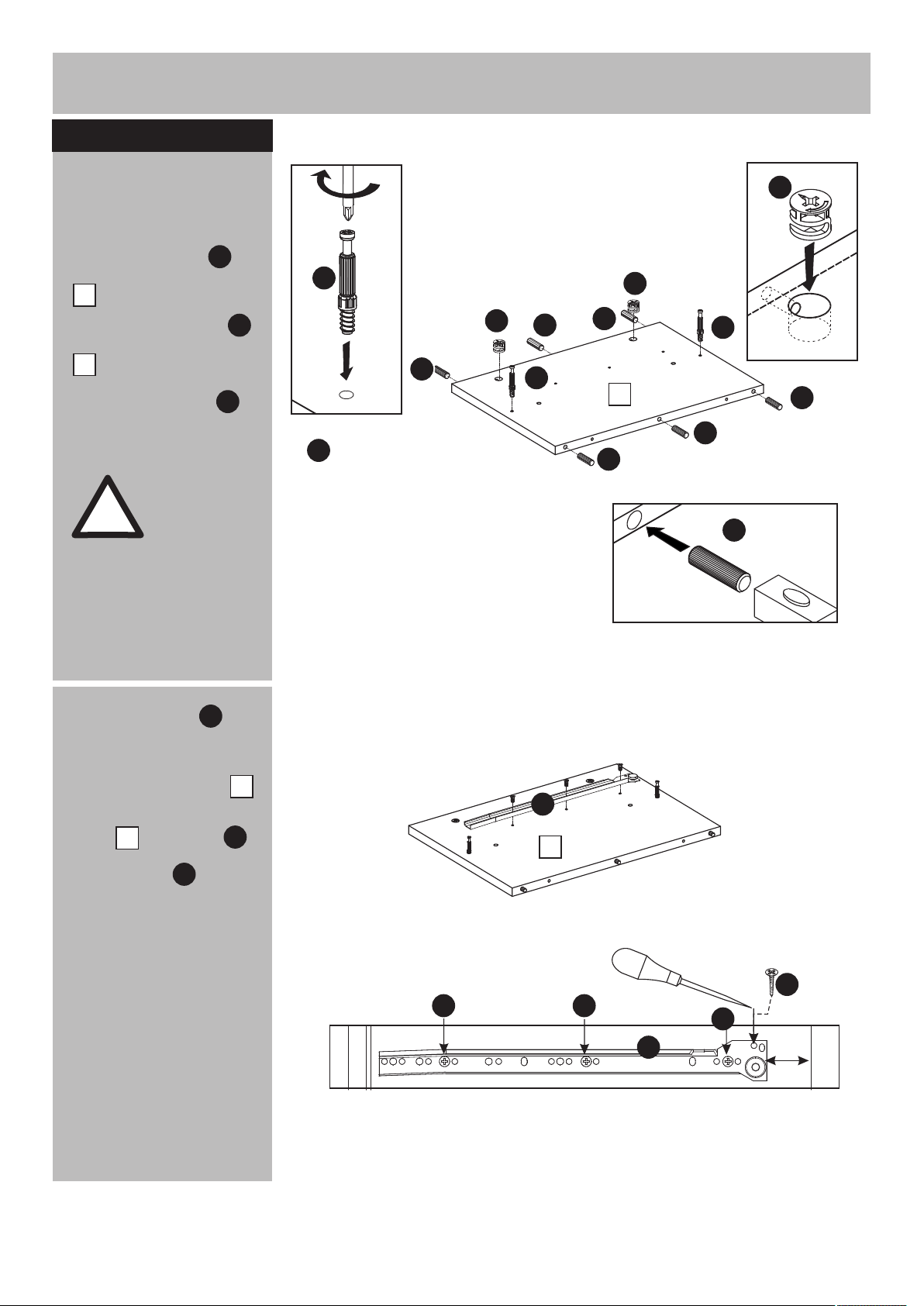
Assembly Instructions
Step 1Step 1
a: Inserting dowels
and locking nuts
Insert locking nuts
into the right side panel
.
2
Insert wooden dowels
into the right side panel
.
2
Screw metal dowels .
WARNING!
Please wear
goggles or
!
protective
eyewear whilst
hammering
dowels in place.
C
E
C
E
A
A
E
C
A
E
C
AA
2
A
E
A
A
A
b: fixing runners
Position runners 40mm
from the front edge
of the right side panel .
Fix runners to right side
panel with screws .
Mark the top right with a
punch. Screw into the
hole.
2
P
2
B
L
b:
P
2
L
BB
P
B
38
5
Page 6

Assembly Instructions
Step 1Step 2
a: Inserting dowels
and locking nuts
Insert locking nuts
into the left side panel
.
1
Insert wooden dowels
into the left side panel
.
1
Screw metal dowels .
WARNING!
Please wear
goggles or
!
protective
eyewear whilst
hammering
dowels in place.
C
E
C
E
A
A
C
A
E
C
AA
1
A
E
A
A
A
b: fixing runners
Position runners 40mm
from the front edge
of the right side panel .
Fix runners with screws .
Mark the top right with a
punch. Screw into the
hole.
P
1
B
L
b:
L
38
P
1
B B
B
P
6
Page 7

Assembly Instructions
Step 1Step 2Step 1Step 3
a: Inserting dowels
and locking nuts
C
Insert locking nuts
into the back .
C
7
A
C
C
C
7
C
C
C
Insert wooden dowels
into the front support
Insert locking nuts .
WARNING!
Please wear
goggles or
!
protective
eyewear whilst
hammering
dowels in place.
Insert wooden dowels
into the back support .
A
5
C
A
6
A
C
A
E
5
C
6
A
E
Insert locking nuts .
Rotate back support &
screw metal dowels .
C
E
C
E
E
A
6
7
Page 8

Assembly Instructions
Step 4
Fittings dowels
E E
Screw metal dowels
into the top .
3
Step 5
Fittings dowels
E
E
A
E
E
E
3
EE
E
into the long plinth .
Repeat with short
14
plinth .
WARNING!
Please wear
goggles or
!
protective
eyewear whilst
hammering
dowels in place.
13
x2
A
13
A
A
A
A
A
x2
14
A
A
A
8
Page 9

Assembly Instructions
Step 6
Attaching panels
Attach right side panel
to the support & .
Attach left side panel
to the support & .
5
5
22
6
1
6
1
5
22
Use the allen key to
turn locking nuts
clockwise to lock.
Cover locking nuts
with caps .
D
K
C
Step 7
Attach back to the
back support
Use the allen key to
turn locking nuts
clockwise to lock.
7
6
K
C
6
A
C
K
E
C
D
7
Cover with caps .
D
6
1
5
C
K
22
D
9
Page 10

Assembly Instructions
Step 8
Attaching panels
Attach top to the left side
panel ,right side panel
& back .
Use the allen key to
turn locking nuts
clockwise to lock.
Cover locking nuts
with caps .
3
1
7
K
C
D
3
22
7
6
1
5
22
A
C
K
E
C
D
Step 9
Attaching plinth
Attach feet to the
long plinth
Attach long plinth
to the short plinth .
!
N
13
13
14
WARNING!
Please wear
goggles or
protective
eyewear whilst
hammering
sliders in place.
N
N
13
14
14
N
N
13
10
Page 11

Assembly Instructions
Step 10
Attaching plinth
Fit long plinth
& short plinth to the
bottom .
13
14
4
Step 11
Mounting bracket
Place mounting
bracket onto the
assembly as shown.
Mark holes with a
punch and fix the
bracket with screws .
R
M
14
13
13
4
R
R
R
R
R
14
R
M
R
R
R
M
11
Page 12

Assembly Instructions
Step 12
Attaching bottom
Attach bottom to the sides
Use hexagon bolt
& allen key .
Cover bolts with caps .
4
F
K
G
2
5
1
F
4
F
F
F
F
K
J
F
G
12
Page 13

Assembly Instructions
Step 13
Drawer assembly
a: drawer back:
10
A
9
C
11
15
Insert wooden dowels
into the drawer back .
b: Insert locking nuts
into the drawer sides ,
& support
Insert wooden
dowels into the
drawer sides & support .
15
A
WARNING!
Please wear
!
goggles or
protective
eyewear whilst
hammering
dowels in place.
a:
A
A
A
A
9
A
b:
C
10
A
A
C
A
C
11
C
15
A
A
A
c: Screw metal dowels
into the drawer front .
d:Fix drawer sides
&
10 11
to the drawer back using
hexagon bolt .
Cover bolts with caps .
F
E
8
9
G
c:
d:
10
F
E
E
E
8
E
11
F
9
F
K
F
J
G
13
Page 14

Assembly Instructions
Step 14
Drawer assembly
a:
a: Attach drawer front
to the drawer sides.
Use the allen key to
turn locking nuts
clockwise to lock.
Cover locking nuts
with caps .
D
8
K
C
8
10
A
C
E
11
12
b: Attach drawer base
using screws &
stabilizer .
!
L
O
IMPORTANT!
Drawer MUST
be “square”
when base is
attached.
12
b:
12
K
O
O
L
L
12
L
L
L
9
C
D
L
L
c: Attach runner using
screws .
14
J
Q
c:
H
J
Q
Q
H
Q
J
Q
12
9
Page 15

Assembly Instructions
Drawer assembly
d: Attach drawer support
to the drawer front .
Use the allen key to
turn locking nuts
clockwise to lock.
Cover with caps .
e drawer support : Fix
using screw .
C
D
T
15
8
K
15
Step 15
d:
e:
A
8
15
12
E
C
9
C
K
D
8
15
T
T
12
9
Leveling
Insert drawer ito the
cabinet.
Attach door handles
using screws .
Place a spirit level on
top .
3
Where necessary, insert
height adjuster to
make top level.
Assembly is complete.
I
S
3
H
3
I
I
H
8
I
I
H
S
If you need help or have damaged or missing parts, call the Customer Helpline: 0845 6400 800
15
 Loading...