

Page 1
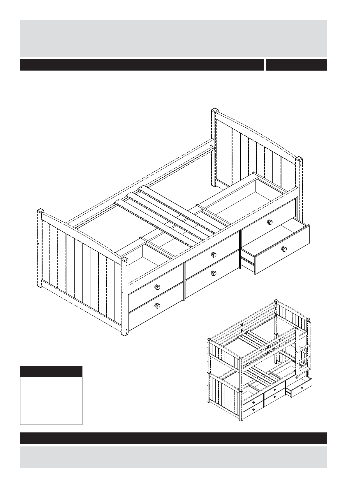
6 Drawer Under Bed Unit - White
Assembly Instructions - Please keep for future reference
4838034
Dimensions
Length - 187cm
Depth - 49cm
Height - 37cm
Weight - 31kg
Important – Please read these instructions fully before starting assembly
If you need help or have damaged or missing parts, call the Customer Helpline:
0045 7668 8055 or e-mail: order@fl exa.dk
Issue 2 - 19/10/15
Page 2
Safety and Care Advice
Important – Please read these instructions fully before starting assembly
• Check you have all the
components and tools listed on
pages 2 and 3.
• Remove all fi ttings from the
plastic bags and separate them
into their groups.
• Keep children and animals
away from the work area, small
parts could choke if swallowed.
• Make sure you have enough
space to layout the parts before
starting.
Care and maintenance
• Only clean using a damp cloth
and mild detergent, do no use
bleach or abrasive cleaners.
• Do not stand or put weight on
the product, this could cause
damage.
• Assemble the item as close
to its fi nal position (in the same
room) as possible.
• Assemble on a soft level
surface to avoid damaging the
unit or your fl oor.
• Parts of the assembly will be
easier with 2 people.
• From time to time check that
there are no loose screws on
this unit.
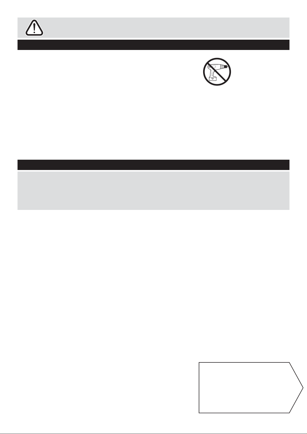
• We do not
recommend the
use of power
drill/drivers for
inserting screws,
as this could
damage the unit. Only use hand
screwdrivers.
• Dispose of all packaging
carefully and responsibly.
• This product should not be
discarded with household waste.
Take to your local authority
waste disposal centre.
Note: if required the next
page can be cut out and used
as reference throughout the
assembly. Keep this page with
these instructions for future
reference.
1
Page 3
If you have damaged or missing components,
Components - Parts
call the Customer Helpline: 0045 7668 8055
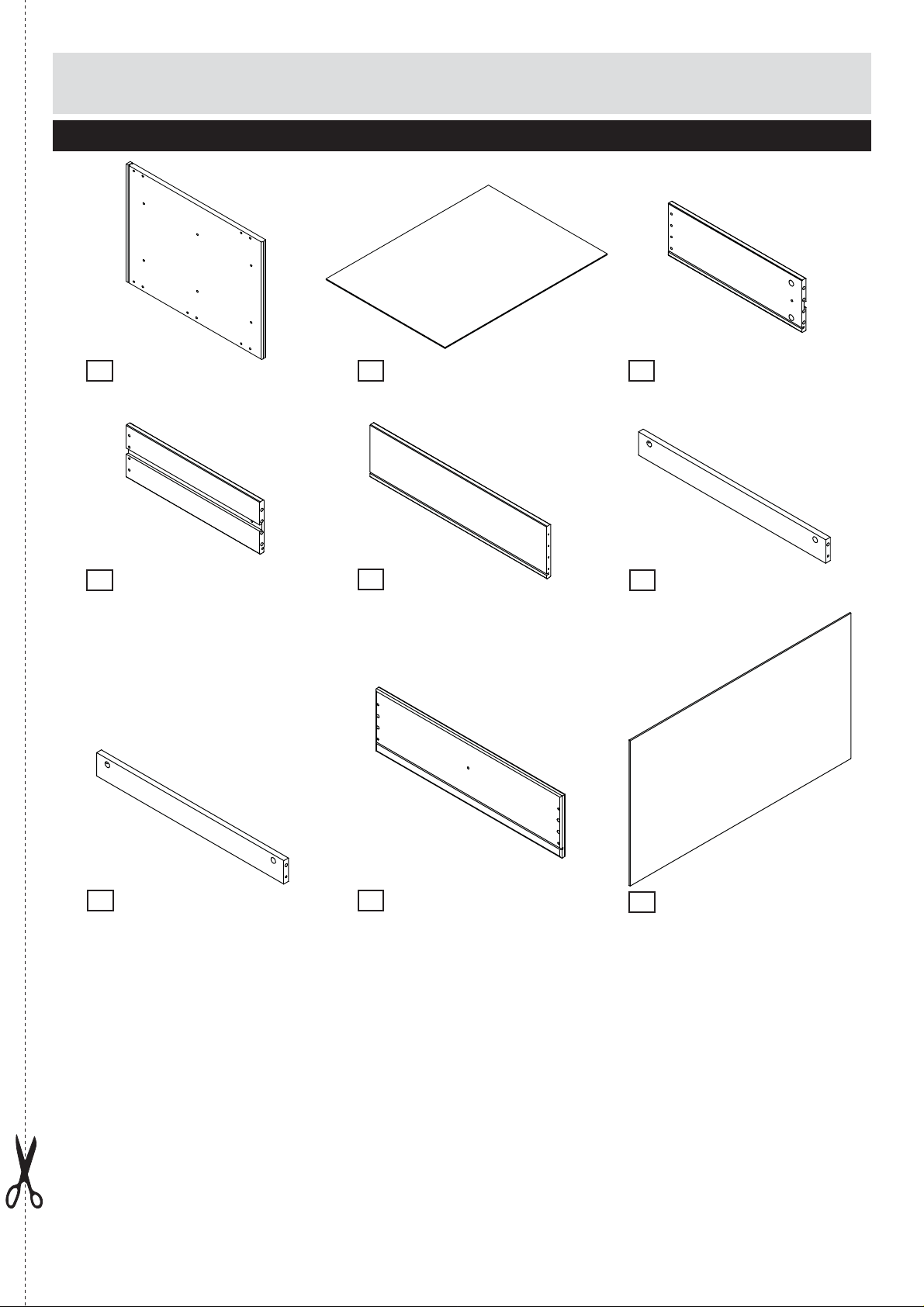
Please check you have all the parts listed below
Side panel x4
1
(36.3x48.5x1.5cm)
No. 15-01503631-20
Drawer side left x6
4
(43.0x14.6x1.3cm)
No. 12-01304302
Drawer base x6
2
(58.0x42.5x0.3cm)
No. 4309-030580
Drawer back x6
5
(56.8x14.6x1.3cm)
No. 12-01305683
Drawer side right x6
3
(43.0x14.6x1.3cm)
No. 12-01304301
Plinth x6
6
(60.2x6.5x1.5cm)
No. 12-01506021
Plinth x6 White
7
(60.2x6.5x1.5cm)
No. 12-01506021-20
Drawer front x6
8
(59.8x17.3x1.5cm)
No. 15-01505983-20
Back panel x3
9
60.9x35.7x0.3cm)
(
No. 4308-030609
2
Page 4
Components - Fittings
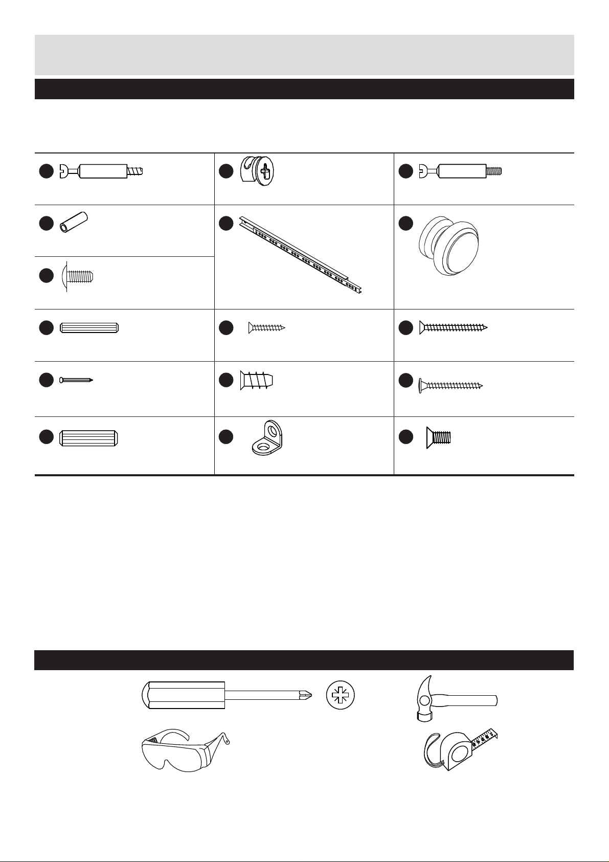
Please check you have all the fi ttings listed below
Note: The quantities below are the correct amount to complete the assembly. In some cases more fi ttings
may be supplied than are required.
No. 4020-005
A
ø7x34mm Minifi x bolt x32
No. 3924-04015
D
ø5x15mm Sleeve connector x20
No. 3912-04009
G
ø9.5/M4x9mm Machine screw x12
No. 3930-05030
H
5x30mm Dowel x24
No. 4022-006
K
1.2x20mm Nail square x50
No. 3930-08030
N
No. 3933-15010
B
ø15x9.5mm Minifi x cam x48
No. 4010-006
E
430x17x10mm Drawer runner x12
No. 3901-40025
i
4.0x25mm Chipboard screw x4
No. 3907-58011
L
ø5.8x11mm Euro screw x12
No. 4008-021
O
No. 4020-006
C
ø7/M4x34mm Minifi x bolt x16
No. 4001-022-20
F
ø40x30mm Knob x6
No. 3901-35040
J
3.5x40mm Chipboard screw x48
No. 3903-40040
M
4.0x40mm Chipboard screw x6
No. 3920-04008
P
8x30mm Dowel x24
Tools required
Phillips
screwdriver
(medium)
Eye protection
(when using a
hammer or glue)
20x20x16x2 Angle x2
ø7,3/M4x8mm Machine screw x24
Small
hammer
Ruler/tape
measure
3
Page 5
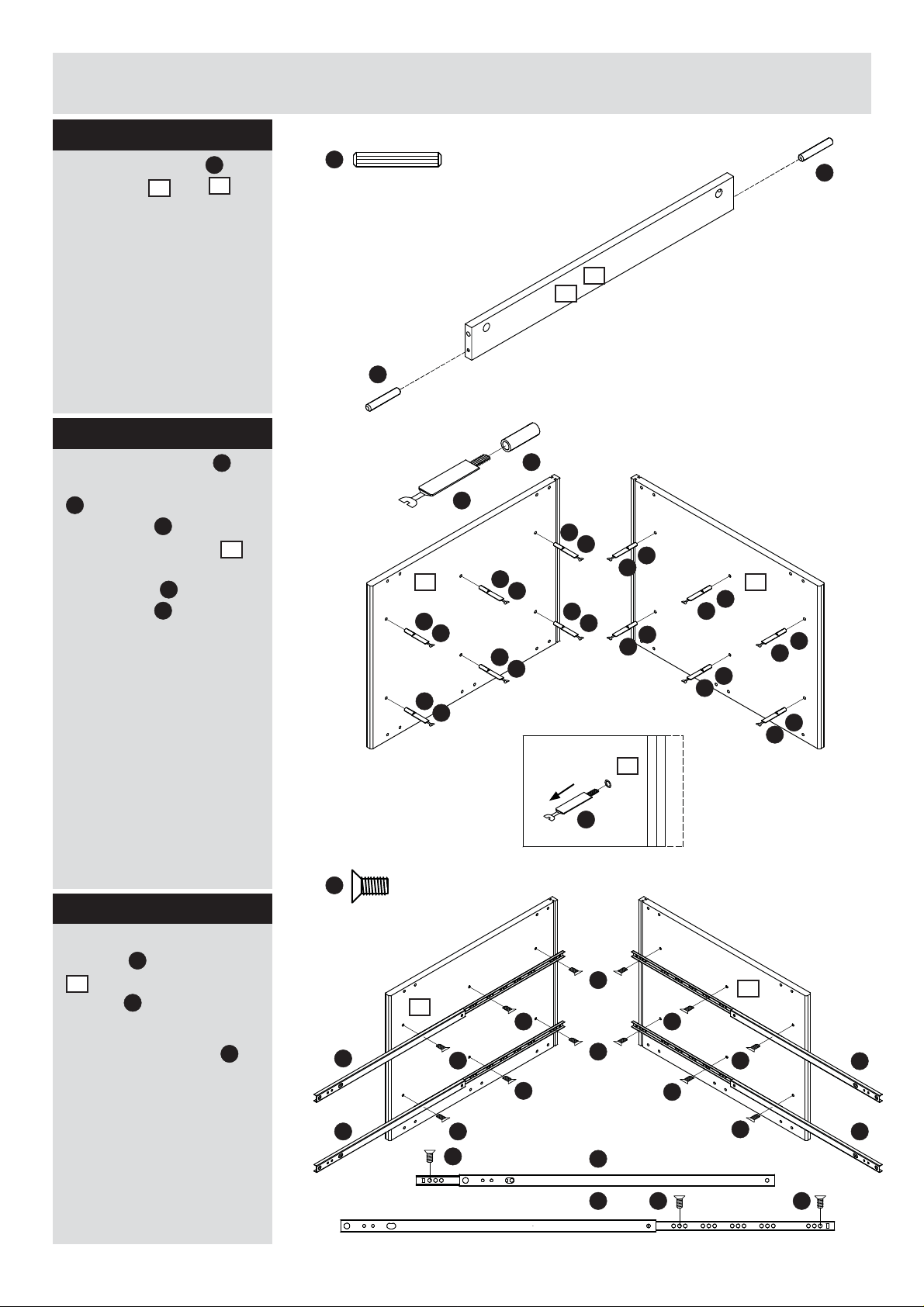
Assembly Instructions
Step 1
Attach the dowels H to
6
the plinths
and 7.
It may be necessary
to tap the dowels in
very gently with a small
hammer.
Repeat for all twelve
plinths.
Step 2
C
Attach minifi x bolts
the sleeve connectors
D
and gently tap the
D
connectors
into the
holes in side panels
(2. and 3.). Unscrew the
C
minifi x bolts
connectors
from the
D
.
to
1
H
H
Middle side Middle side
1
D
Front edge
D
(2.)
C
C
H
x12
7
6
D
C
D
C
D
C
D
C
D
C
D
C
C
D
C
C
1
D
D
(3.)
C
D
Front edge
D
C
Step 3
Attach the drawer
E
runners
1
(2. and 3.) using
screws
Important! Do not
tighten the screws
until all 3 screws are
inserted into the holes.
Be aware of the forward
end!
to side panels
P
.
P
1
C
P
Middle sideMiddle side
(2.)
P
1
P
P
1
(3.)
Front edge
E
E E
P
P
P
P
Front edge
P
P
E
E
P
P
P
P
Front edge
E
44
Page 6
Assembly Instructions
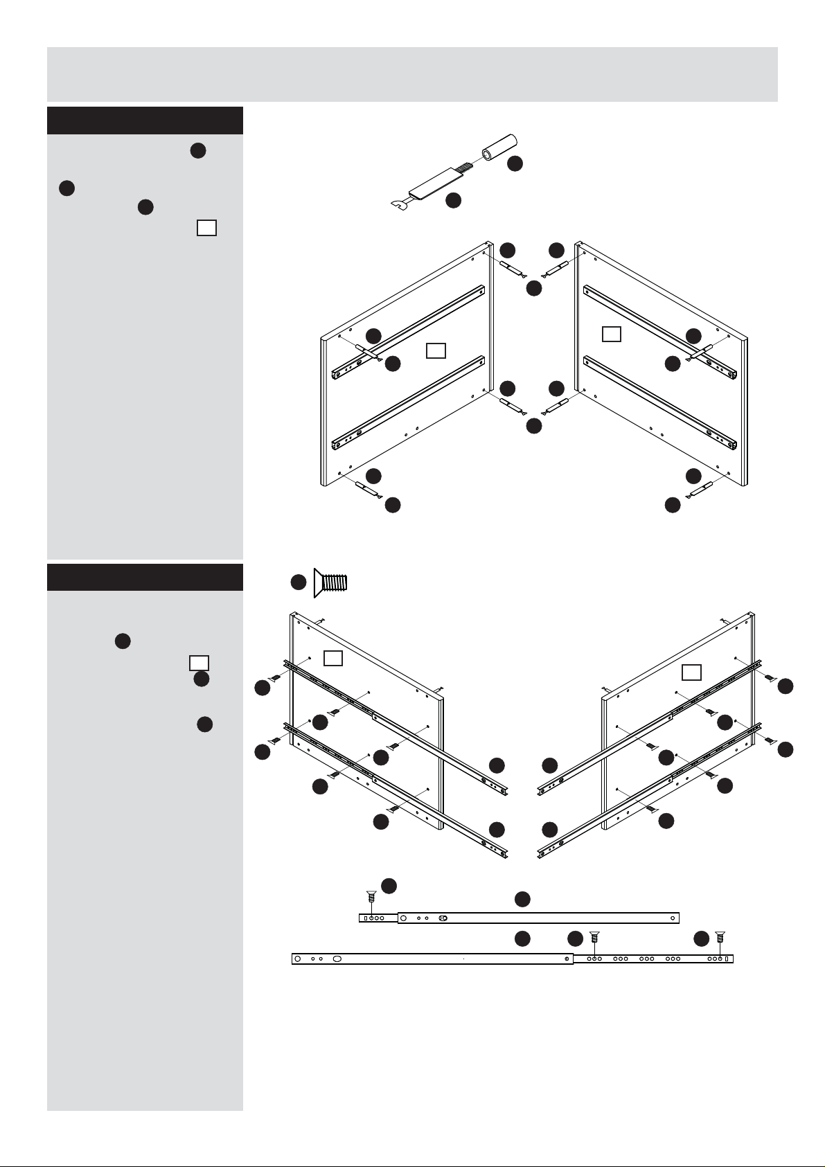
Step 4
Attach minifi x bolts C to
the sleeve connectors
D
and gently tap the
D
connectors
holes in side panels
into the
1
(2. and 3.).
D
C
D
Middle side Middle side
D D
C C
Front edge
D D
C C
(2.)
1
D
D
C
1
(3.)
D
C
Front edge
Step 5
Flip the side panel over
and attach the drawer
E
runners
side of side panels
and 3.) with screws
Important! Do not
tighten the screws
until all 3 screws are
inserted into the holes.
Be aware of the forward
end!
to the other
1
P
P
(2.
.
P
1
P
P
(2.)
P
P
Front edge
Front edge
P
P
P
E E
E E
E
E P
Middle sideMiddle side
Front edge
P
(3.)
1
P
P
P
P
P
P
5
Page 7
Assembly Instructions
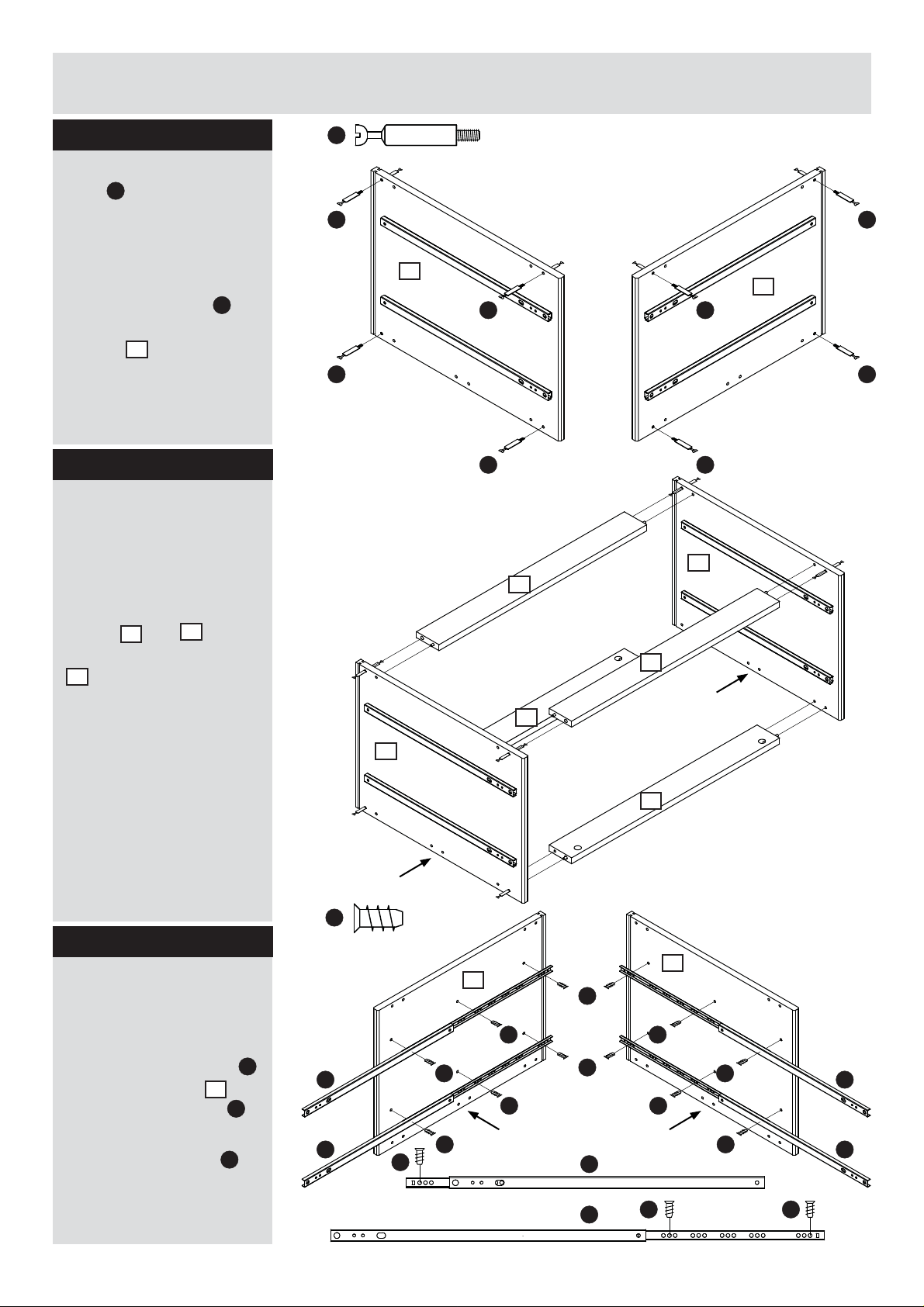
Step 6
Please note! The minifi x
C
bolts
should only
be tightened with your
fi ngers, not tightened into
the wood/panels using a
screwdriver.
C
Attach minifi x bolts
to the other side of side
1
panels
(2. and 3.).
Step 7
Please note! Make sure
the 2 small holes in the
panels are facing down
against the fl oor.
Assemble the middle
section by placing the
6
plinths
between the side panels
1
(2. and 3.).
and 7
C
Middle sideMiddle side
C
1
(2.)
C C
C C
C C
6
Front edge
Front edge
1
(3.)
7
(3.)
1
!
6
C
Step 8
Please note! Make sure
the 2 small holes in the
panels are facing down
against the fl oor.
Attach drawer runners
1
to the side panels
and 4.) using screws
Important! Do not
tighten the screws
until all 3 screws are
inserted into the holes.
(1.
L
L
1
(2.)
7
!
L
Left side Right side
Front edge
E
E E
.
E E
L
Front edge
(1.)
1
L
L L
L L
L L
L L
!
L
E
E
1
(4.)
Front edge
!
L L
6
Page 8
Assembly Instructions
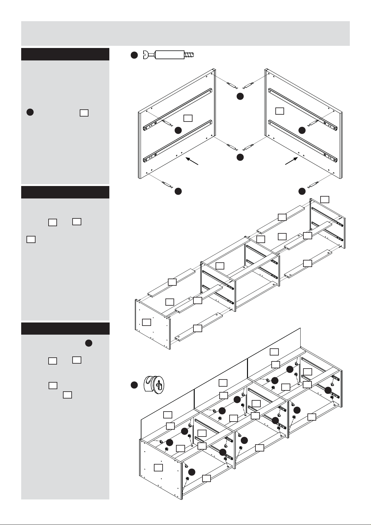
Step 9
Please note! Make sure
the 2 small holes in the
panels are facing down
against the fl oor.
Attach the minifi x bolts
A
to side panels 1 (1.
and 4.)
Step 10
Assemble the left and
right section by placing
6
plinths
between the side panels
1
(1. and 2. and 3. and
4.)
and 7
A
Left side Right side
Front edge
A
(1.)
1
A A
A
!
A A
1
1
(4.)
!
6
6
(3.)
Front edge
1
(4.)
7
Step 11
B
Insert minifi x cams
into the holes in the
6
plinths
and 7 and
tighten the cams using a
screwdriver. Slide back
9
panels
side panels
into grooves in
1
.
1
(2.)
6
6
1
(1.)
B
9
6
B
7
7
9
6
9
6
B
B
6
B
1
6
7
B
7
B
B
6
1
B
7
7
B
1
7
B
B
7
1
B
7
7
Page 9
Assembly Instructions
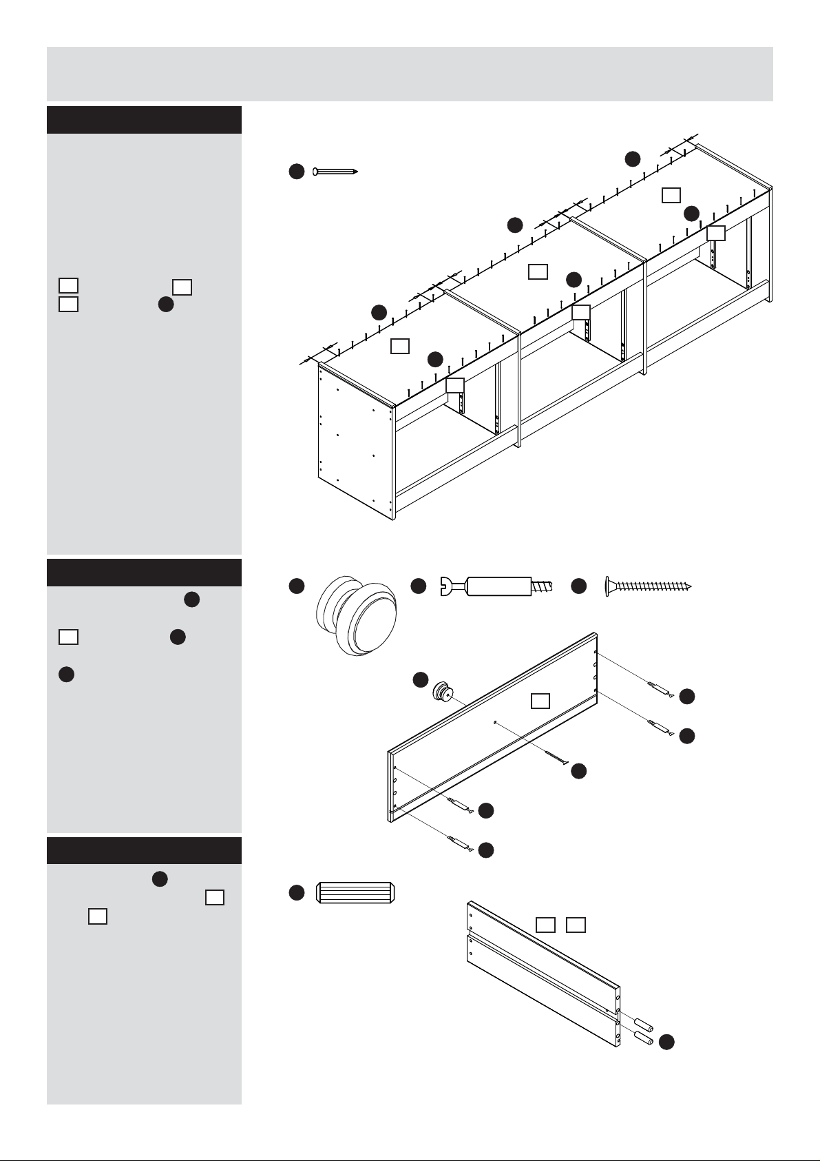
Step 12
Please note! The nails
should be positioned at
least 5 cm from the side
panels. If not, the nail
may hit the minifi x cam in
the plinth.
K
5cm
K
5cm
5cm
K
9
K
7
Attach the back panels
9
to the plinths 6 and
7
using nails K. Make
sure that there is no gap
between the plinths and
the back panels.
Step 13
A
Insert minifi x bolts
holes in the drawer front
8
. Attach knob F to the
drawer front using screw
M
.
Repeat for all six
drawer fronts.
into
F
5cm
5cm
5cm
K
9
K
7
A
F
9
K
7
M
8
A
A
Step 14
Insert dowels
holes in drawer sides
4
and
.
Repeat for all twelve
drawer sides.
N
into
M
A
A
3
N
3 4
/
N
8
Page 10
Assembly Instructions
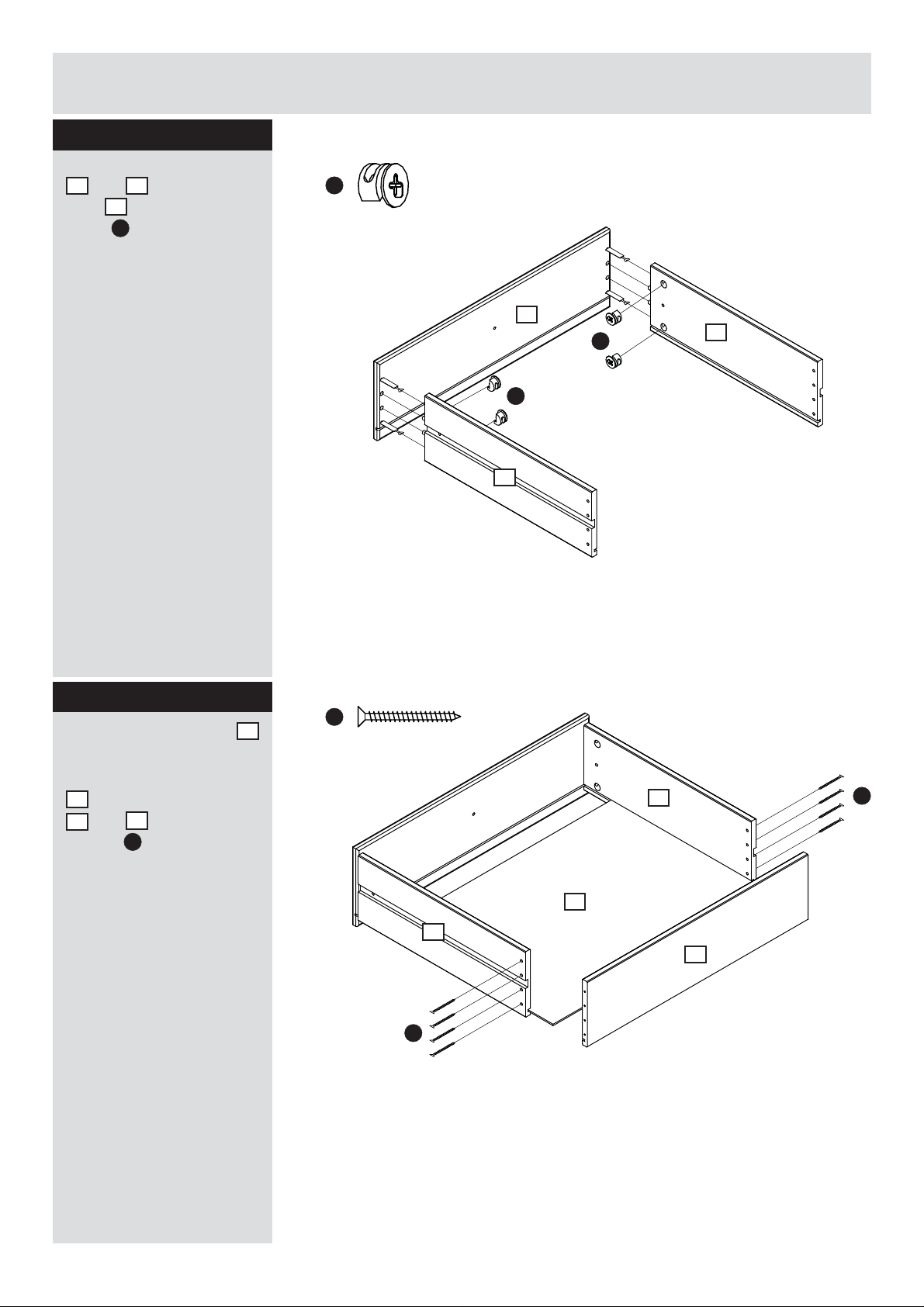
Step 15
Attach the drawers sides
3
and 4 to the drawer
8
front
cams
using minifi x
B
.
Repeat for all six
drawers.
B
8
B
B
3
4
Step 16
Push the drawer base
carefully into the drawer.
Attach the drawer back
5
to the drawer sides
3
and 4 with the
J
screws
Repeat for all six
drawers.
.
2
J
4
2
3
5
J
J
9
Page 11
Assembly Instructions
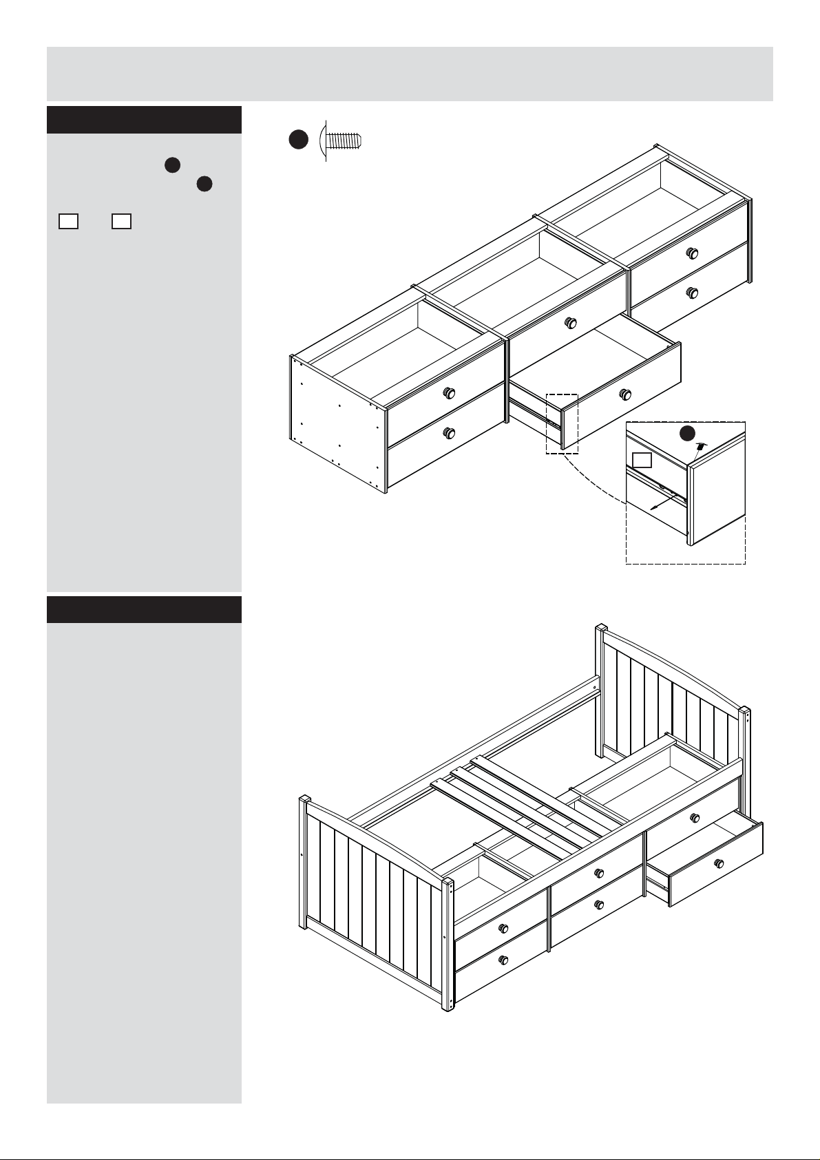
Step 17
Attach the drawer to the
E
drawer runners
the machine screws
inside to the drawer sides
3
and 4.
Repeat for all six
drawers.
with
G
G
G
4
Step 18
Position the bed where
it will be placed in the
future, before attaching
the 6 drawer underbed
unit to the bed. Bed and
6 drawer unit can’t be
moved together after the
unit has been attached
to the bed with the 2
brackets.
10
Page 12
Assembly Instructions
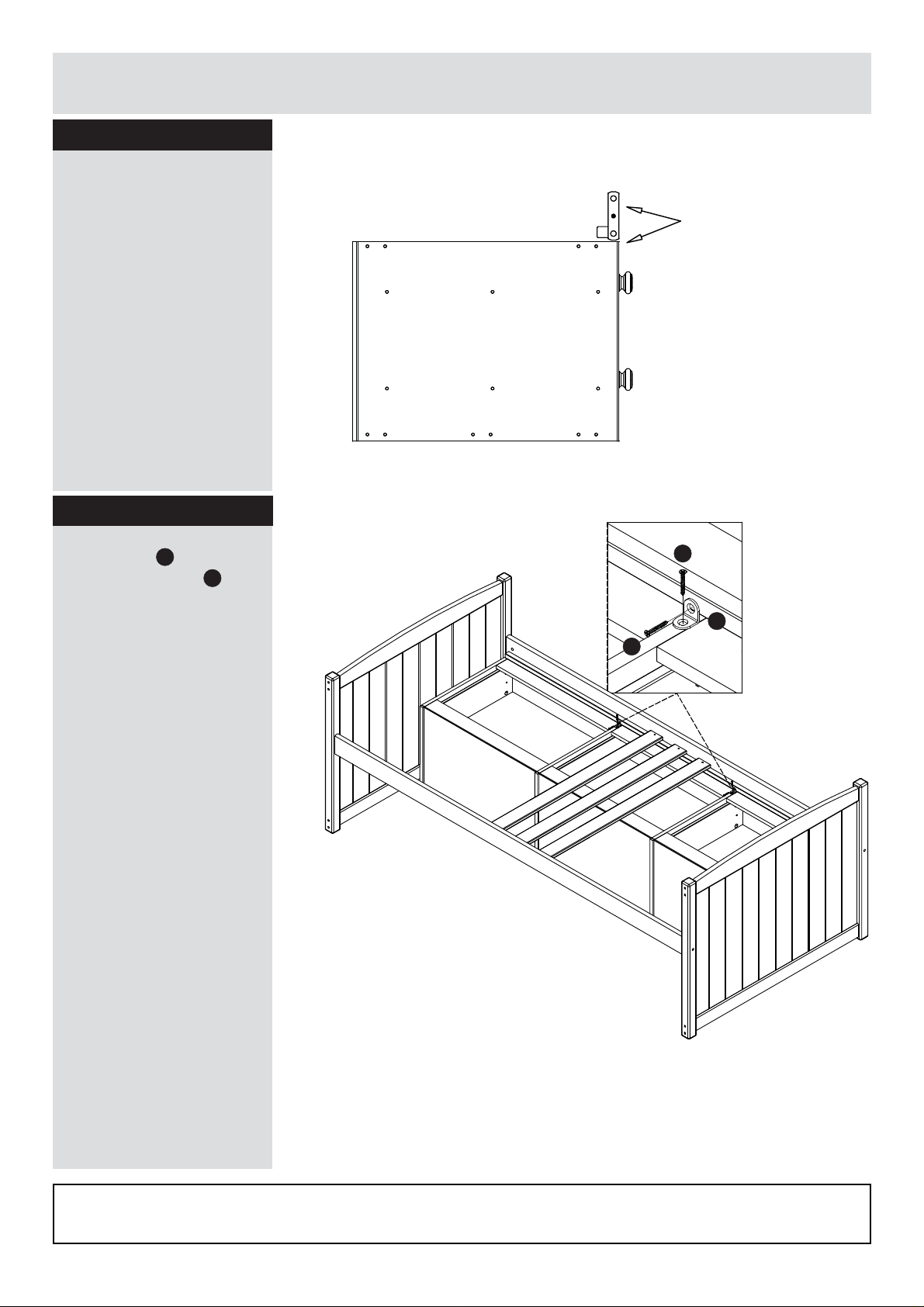
Step 19
The underbed unit should
be fl ush with the bedside
rail.
Step 20
Unit fl ush with the
bedside rail.
Secure the unit in place
O
with angles
chipboard screws
Assembly is complete.
and
i
.
i
O
i
If you need help or have damaged or missing parts,
E-mail: order@fl exa.dk
Ref.no. 44-01529-20 B Stand: 191015 Page 12 (81-07709-20)
11
call the Customer Helpline: 0045 7668 8055
 Loading...