

Page 1
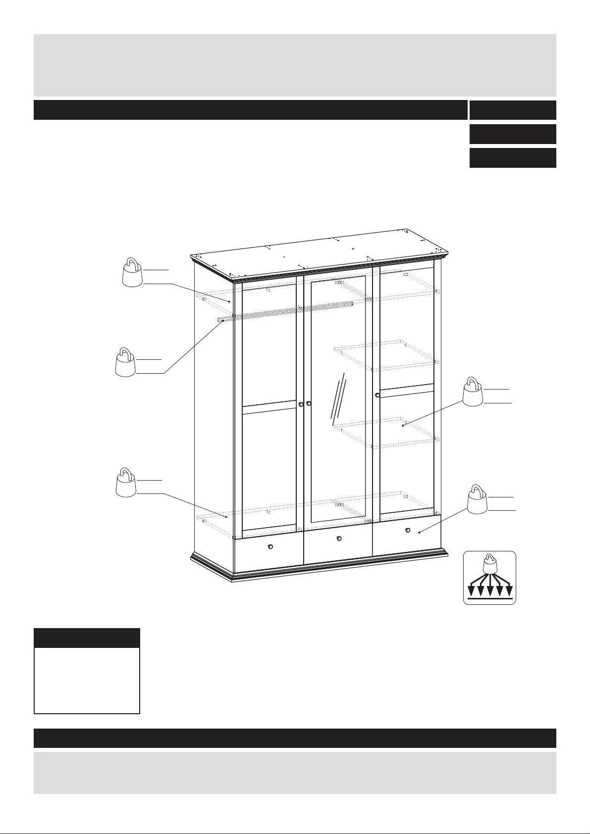
Canterbury 3 DR 3 DRW MIR ROBE
Assembly Instructions - Please keep for future reference
kg20
lbs
44
kg25
lbs
55
483/6469
498/1912
499/9760
kg30
lbs
66
kg20
lbs
44
max.
Dimensions
Width - 152.8cm
Depth - 62.7cm
Height - 202.1cm
Important – Please read these instructions fully before starting assembly
18
kg8
lbs
If you need help or have damaged or missing parts, call the Customer Helpline:
Argos = 0345 6400800
71939 Version E Date 14/06/2016
Page 2
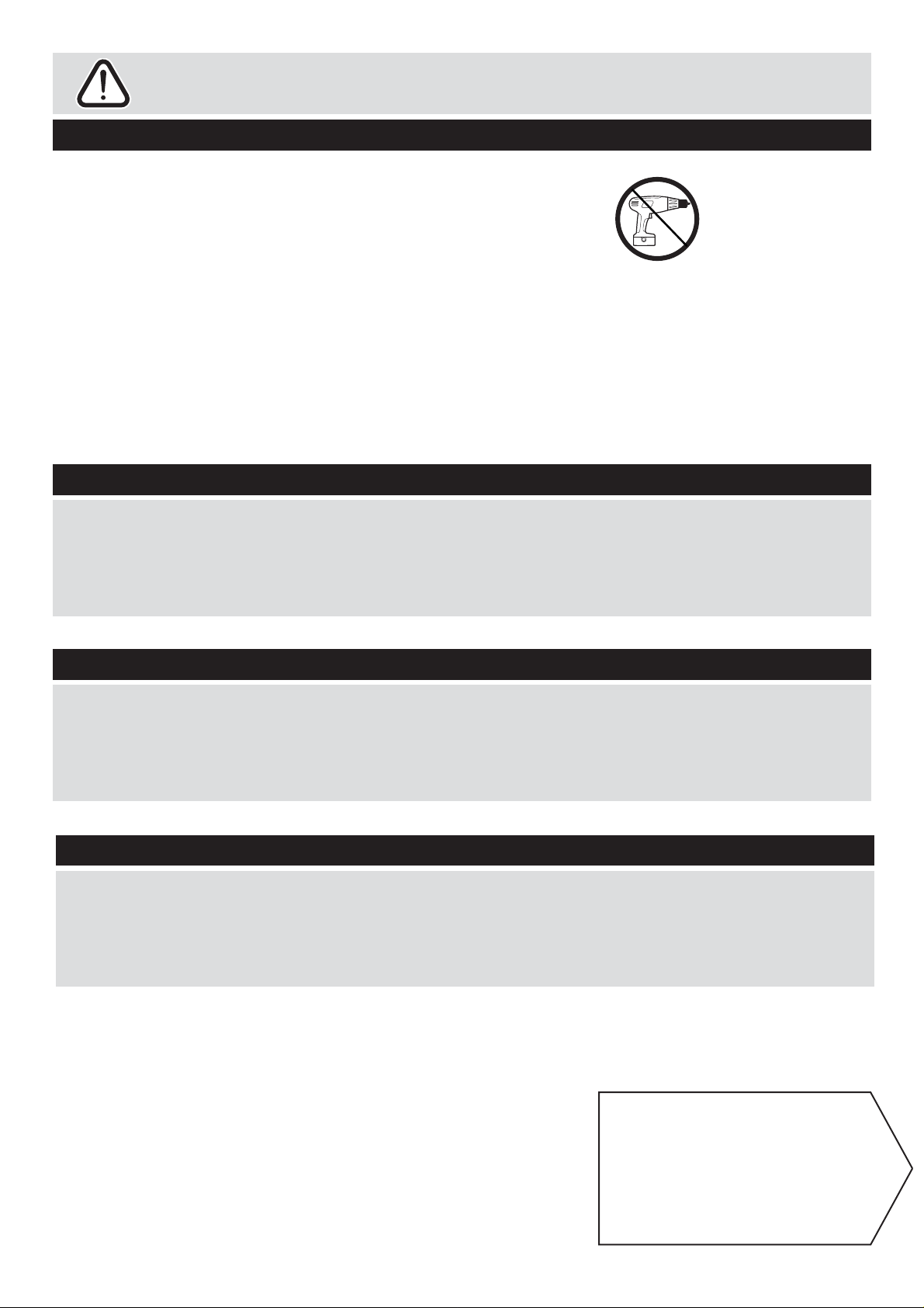
Safety and Care Advice
Important – Please read these instructions fully before starting assembly
• Check you have all the
components and tools listed on
the following pages.
• Remove all fi ttings from the
plastic bags and separate them
into their groups.
• Keep children and animals
away from the work area, small
parts could choke if swallowed.
• Make sure you have enough
space to lay out the parts before
starting.
Care and maintenance
• Only clean using a damp cloth
and mild detergent, do no use
bleach or abrasive cleaners.
• During assembly, do not stand
or put weight on the product,
this could cause damage.
• Assemble the item as close
to its fi nal position (in the same
room) as possible.
• Assemble on a soft level
surface to avoid damaging the
unit or your fl oor.
• Parts of the assembly will be
easier with 2 people.
• From time to time check that
there are no loose screws on
this unit.
• We do not
recommend the use
of power drivers for
inserting screws, as
this could damage
the unit. Only use hand screw
drivers.
• This product should not be
discarded with household waste.
Take to your local authority
waste disposal centre.
Handy Hints
• Assemble all parts and bolts
loosely during assembly, only
once the product is complete
should you fully tighten the bolts
Safety
• The provided tip-over restraint
must be installed in order to
optimize user safety.
• Regularly check and ensure
that all bolts and fi ttings are
tightend properly.
Note: if required the next
page can be cut out and used
as reference throughout the
assembly. Keep this page with
these instructions for future
reference.
1
1
Page 3
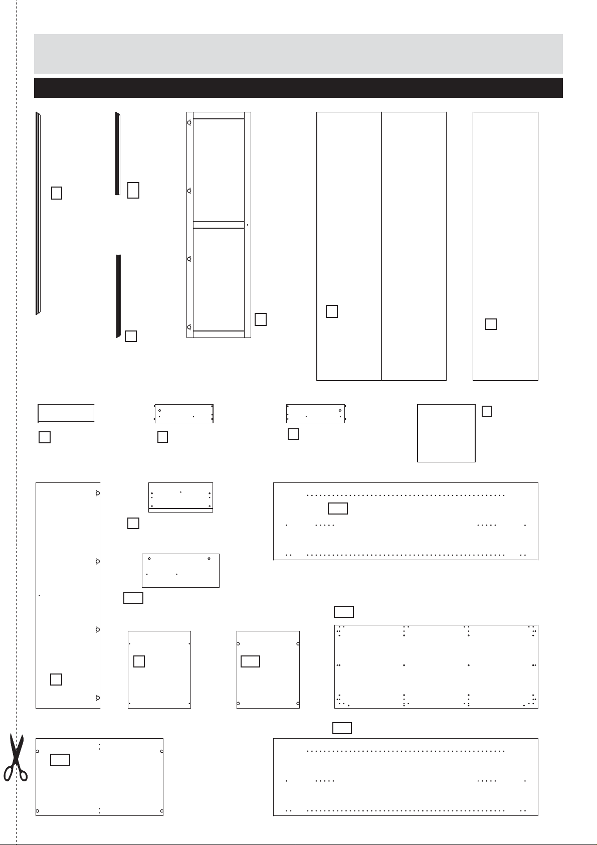
If you have damaged or missing components, call the
Components - Panels
Customer Helpline:
Please check you have all the panels listed below
Argos = 0345 6400800
N
76431 Profi le side
(152 x 4cm) x2
C
02748 Drawer back
(42.1 x 14cm) x3
M
76428 Profi le side
(62 x 2,5cm) x2
L
76427 Profi le side
(62 x 2,5cm) x2
B
00487 Right drawer side
(43.5 x 14cm) x3
18731Frame door (169.3 x 48.2cm) x2
K
A
00486 Left drawer side
(43.5 x 14cm) x3
09789 Back panel (201.5 x 97.4cm)
H
09790 Back panel (201.5 x 48.9cm)
J
D
06294 Drawer bottom
(43.3 x 43.3cm) x3
Drawer front
E
(48.2 x 22.1cm) x3
Small divider panel (25 x 57.8cm)
GA
Door w. mirror (169.3 x 48.2cm)
W
UB
Large fi xed shelf
(95.5 x 57.9cm) x2
T
Loose shelf
(47 x 58cm) x2
UC
Small fi xed shelf
(47 x 58cm) x2
FA
Side panel L/R (198.8 x 58cm) x2
IC
Bottom / top panel (152,8 x 62.4cm) x2
GB
Large divider panel (198.8 x 58cm)
2
2
Page 4
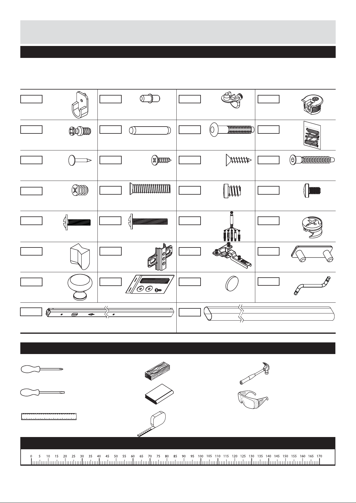
Components - Fittings
Please check you have all the fi ttings listed below
Note: The quantities below are the correct amount to complete the assembly. In some cases more fi ttings
may be supplied than are required.
10601 11011 11042
Holder x2
11230 20203
Screw (ø5 x 7mm) x16
23010
Big nail x18
26020
Flat head screw
(ø5.8x9mm) x12
26221 26232
Machine screw
(M4x15mm) x12
33204
Wedges x4
Drawer support x6 Shelf support x8
20228
Dowel (ø5x30mm) x16
25215 25610
Flat head screw
(ø3x12mm) x2
Drawer fastener x12
25233
Flat head screw
(ø3.5x15mm) x6
26033 26071
Flat head screw
(ø6.3x27mm) x20
Screw (ø7x8mm) x24
31513 31687
Machine screw
(M4x23mm) x6
50491
Hinge plate x12
52291
Hinge x12
11229
Bracket x16
25 pcs
23006
Nails x3
Connector bolt
(ø7x50mm) x21
26211
Machine screw
(M4x7mm) x12
Cam x8Cam bolt x8
63008
Floor glider x8
81040
Handle x6
41434
Drawer runner x6
94009
Strap x2
96203
Stop x6
72509
Hanger x1
Tools required
Cross head screwdriver
(medium & large)
Flathead screwdriver
(medium)
01 02 03 04 05 06 07 08 09 0 100 110 120 130 140 150
01 23 45 6
Ruler
wooden block
Books X6
Tape measure
Ruler - Use this ruler to help correctly identify the screws
97642
Allen key x1
Hammer
Eye protection
(when using a
hammer or glue)
3
Page 5
Assembly Instructions
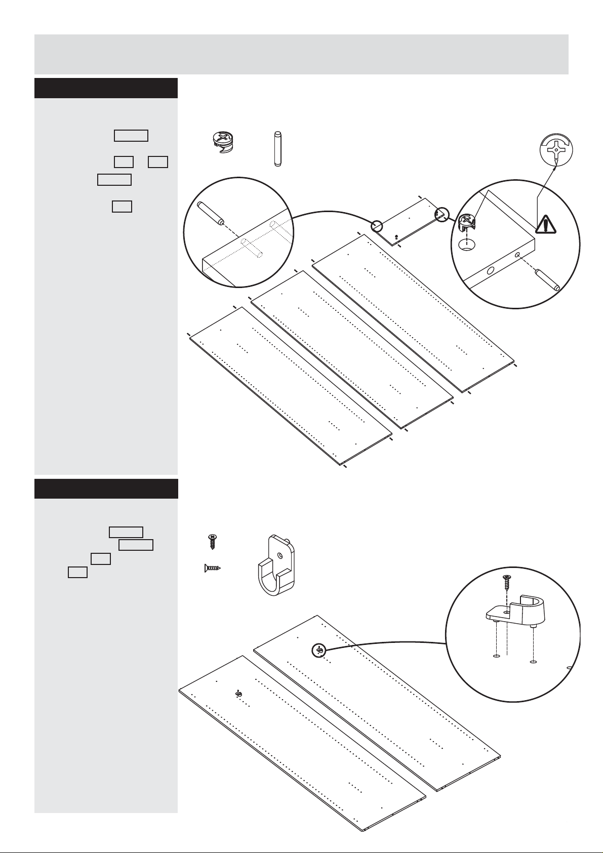
Step 1
Fittings you will need for this step:
Insert dowles
Insert dowels 20203
into outer holes on the
ends of panel FA + GB
Place cam 31687 into
the holes on top of small
divider panel GA .
Cam
# 31687 X2
Dowel
# 20203 X16
Arrow facing the edge of
the panel.
Step 2
Attaching hanger holder
Attach holder 10601 with
fl at head screw 25215 on
side panel FA and divider
panel GB .
FA
Fittings you will need for this step:
Flat head screw
# 2215 X2
Holder
# 10601 X2
GA
FA
GB
FA
GB
4
4
Page 6
Assembly Instructions
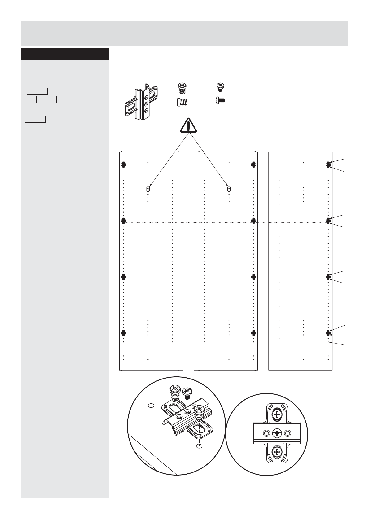
Step 3
Fittings you will need for this step:
Attaching hinge plate
Fixing each hingplate
50491 with screw
2x 26071 .
Insert machine screw
26211 in center of
hinge plate.
Hinge
# 50491 X12
Screw
# 26071 X24
Machine screw
# 26211 X12
49
48
FA
GB
36
35
FA
20
19
4
3
1
5
5
Page 7
Assembly Instructions
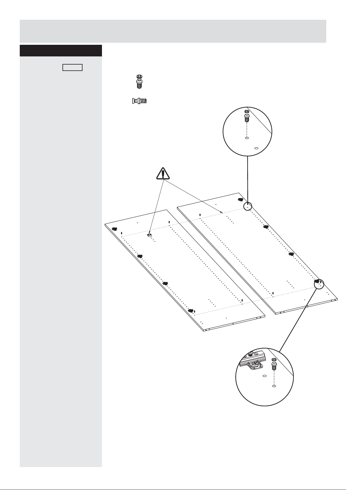
Step 4
Fittings you will need for this step:
Attach screw 11230 as
shown.
Screw
# 11230 X8
FA
FA
6
6
Page 8
Assembly Instructions
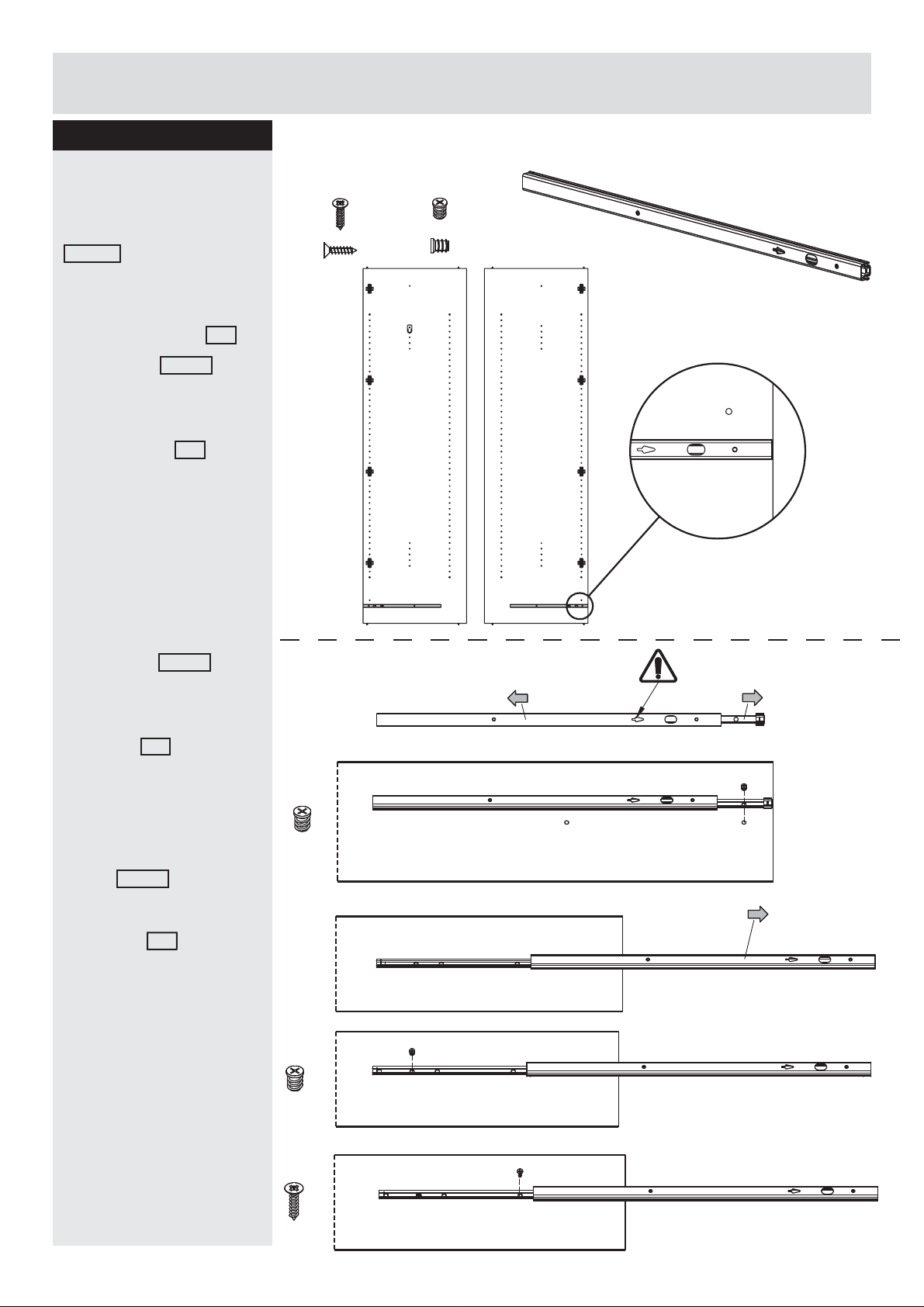
Step 5
Fittings you will need for this step:
Place drawer runners
1.
Extend drawer glide
41434 .
2.
Attach drawer glide at the
front of side panel FA .
Place screw 26020
through the correct hole
at the front of the drawer
glide, into the holes on
the side panel FA .
Tighten screw but do not
overtighten.
Flat head screw
# 25233 X2
Flat head screw
# 26020 X4
FA
FA
Drawer runner
# 41434 X2
3.
Open slide until 3 holes
is visible at back of
drawer glide.
4.
Place screw 26020
through the correct holes
at the back of the drawer
glide, into the holes on
the panel FA .
Tighten screw but do not
overtighten.
5.
Attach the fl at head
screw 25233 into the
correct holes of the
drawer glide, into the
side panel FA .
Tighten screw but do not
overtighten.
1.
2.
3.
Front
x1
Front
Front
Repeat these 5 steps for
the remaining runners.
7
5
4.
x1
5.
x1
Front Front Front
Page 9
Assembly Instructions
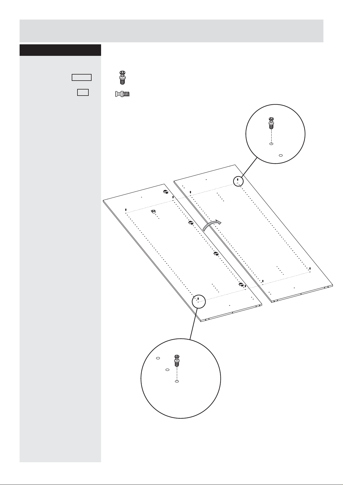
Step 6
Fittings you will need for this step:
Drawer supporter
Attach the screw 11230
on both sides of the
large divider panel GB .
Screw
# 11230 X8
GB
Bottom
8
6
Page 10
Assembly Instructions
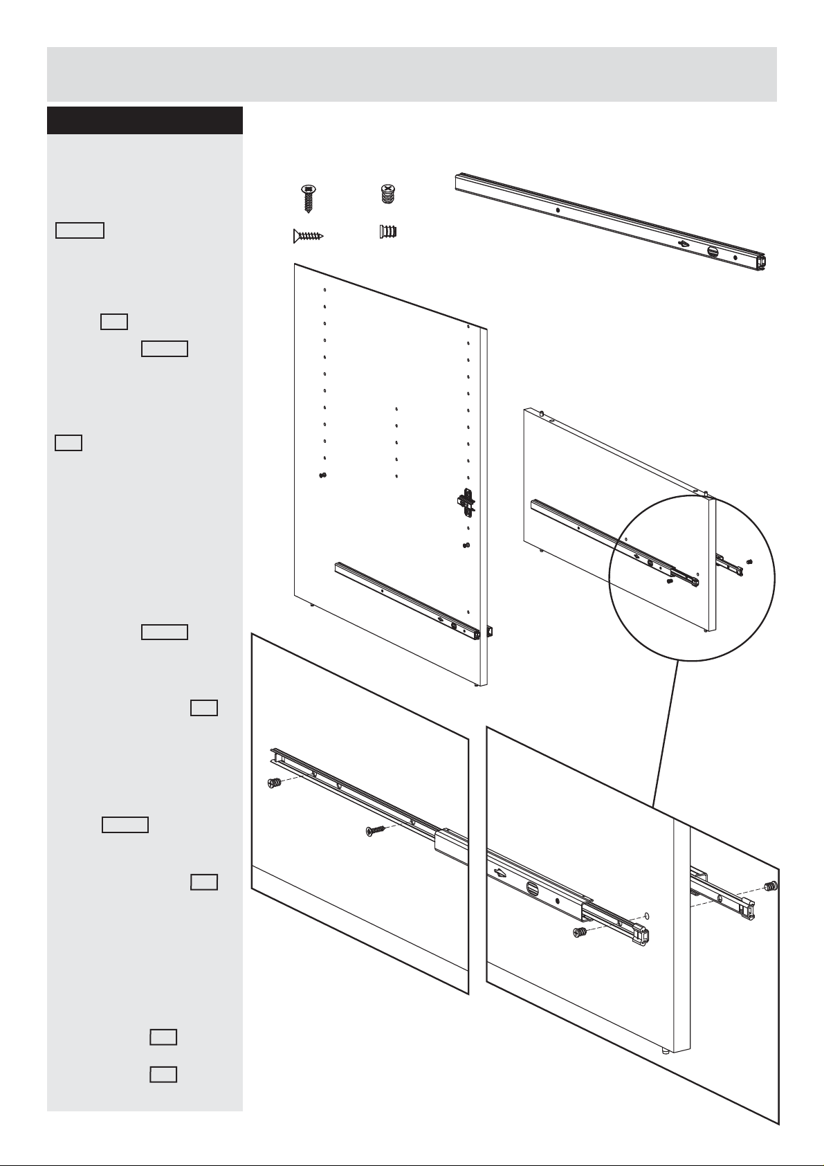
Step 7
Fittings you will need for this step:
Place drawer runners
1.
Extend drawer glide
41434 .
2.
Attach drawer glide at
the front of small divider
panel GA .
Flat head screw
# 25233 X4
Flat head screw
# 26020 X8
Drawer runner
# 41434 X4
Place screw 26020
through the correct hole
at the front of the drawer
glide, into the holes on
the small divider panel
GA .
Tighten screw but do not
overtighten.
3.
Open slide until 3 holes
is visible at back of
drawer glide.
4.
Place screw 26020
through the correct holes
at the back of the drawer
glide, into the holes on
small divider panel GA .
Tighten screw but do not
overtighten.
GB
GA
Front
Front
Bottom
5.
Attach the fl at head
screw 25233 into the
correct holes of the
drawer glide, into the
small divider panel GA .
Tighten screw but do not
overtighten.
Repeat these 5 steps for
the remaining runners on
the other side of small
divider panel GA and
on both sides of large
divider panel GB .
9
Page 11
Assembly Instructions
Step 8
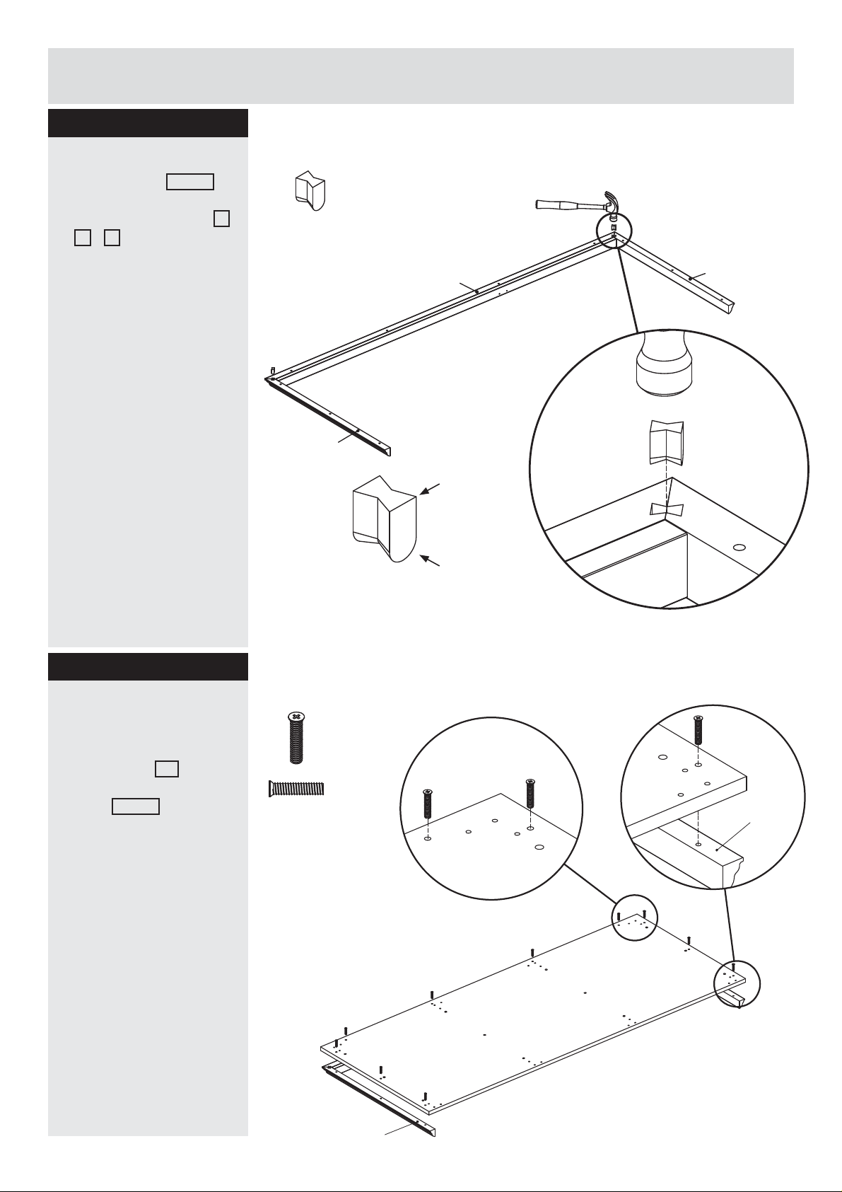
Fittings you will need for this step:
Gathering profi les
Insert wedges 33204 into
slots on the angle ends of
side and front profi les L
+ N + M .
Wedges
# 33204 X4
Use a hammer.
Step 9
Attaching panels
Attach the gathering
profi les as shown.
N
x2
L
Top
Bottom
Fittings you will need for this step:
Flat head screw
# 26033 X20
M
Place bottom IC as
shown, insert fl at head
screw 26033 .
M
IC
x2
L
10
Page 12
Assembly Instructions
Step 10
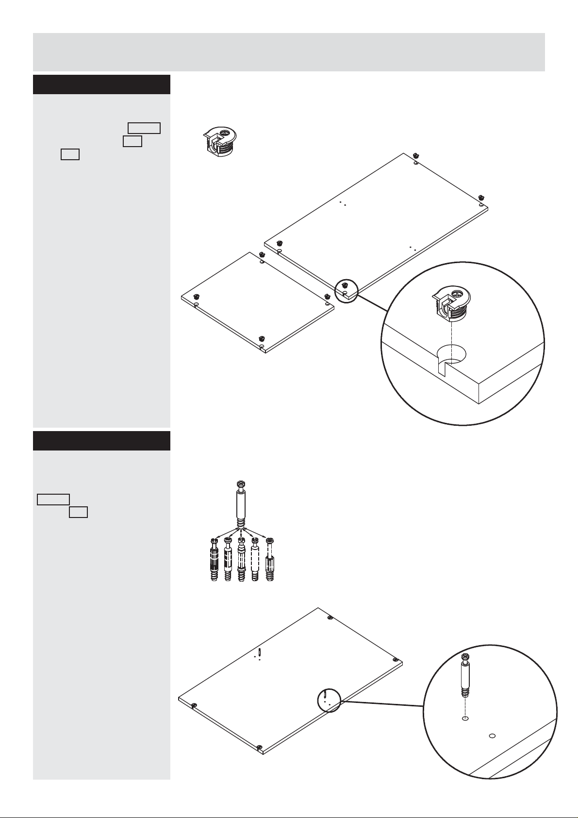
Fittings you will need for this step:
Place brackets
Place the bracket 11229
in the fi xed shelf UB
and UC .
Bracket
# 11229 X16
UC
(x2)
UB
(x2)
Step 11
Insert cam bolt
Insert the cam bolts
31513 into the fi xed shelf
panel UB .
Cam bolts must be
screwed down fl ush.
Fittings you will need for this step:
Cam bolt
# 31513 X2
UB
11
Page 13
Assembly Instructions
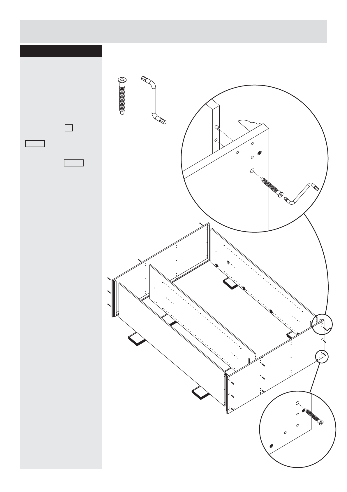
Step 12
Fittings you will need for this step:
Attaching top and
bottom panel
Lay down the cabinet
facing the front to the
fl oor. Using books
supplying side panels.
Attach the top and
bottom panel IC by
inserting connector bolt
25610 into the holes.
Tighten the screws with
the allen key 97642 .
Using books, supporting
side panels and divider
panel.
Connector bolt
# 25610 X18
Allen key
# 97642 X1
FA
IC
FA
GB
IC
12
Page 14
Assembly Instructions
Step 13
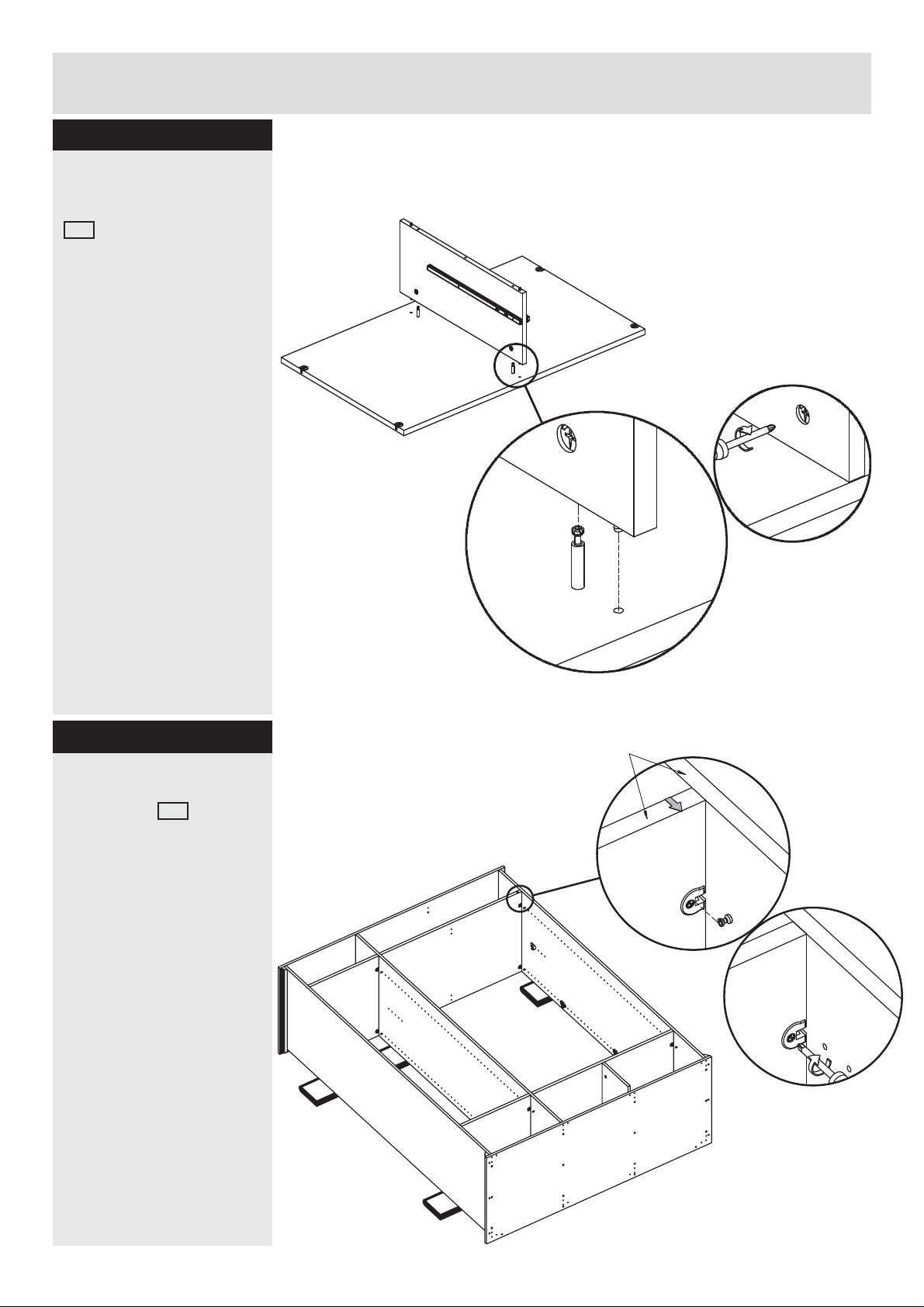
Attaching divider panel
Attach the divider panel
GA by inserting dowel
pins and cam bolts into
the holes.
Tighten the cams.
GA
Step 14
Attaching shelf
Place shelf UB as
picture and slide down
over screw.
Then tighten.
UC
FA
Unfinished edge
IC
UB
FA
GB
UB
UC
IC
13
Page 15
Assembly Instructions
v
Step 15
Fittings you will need for this step:
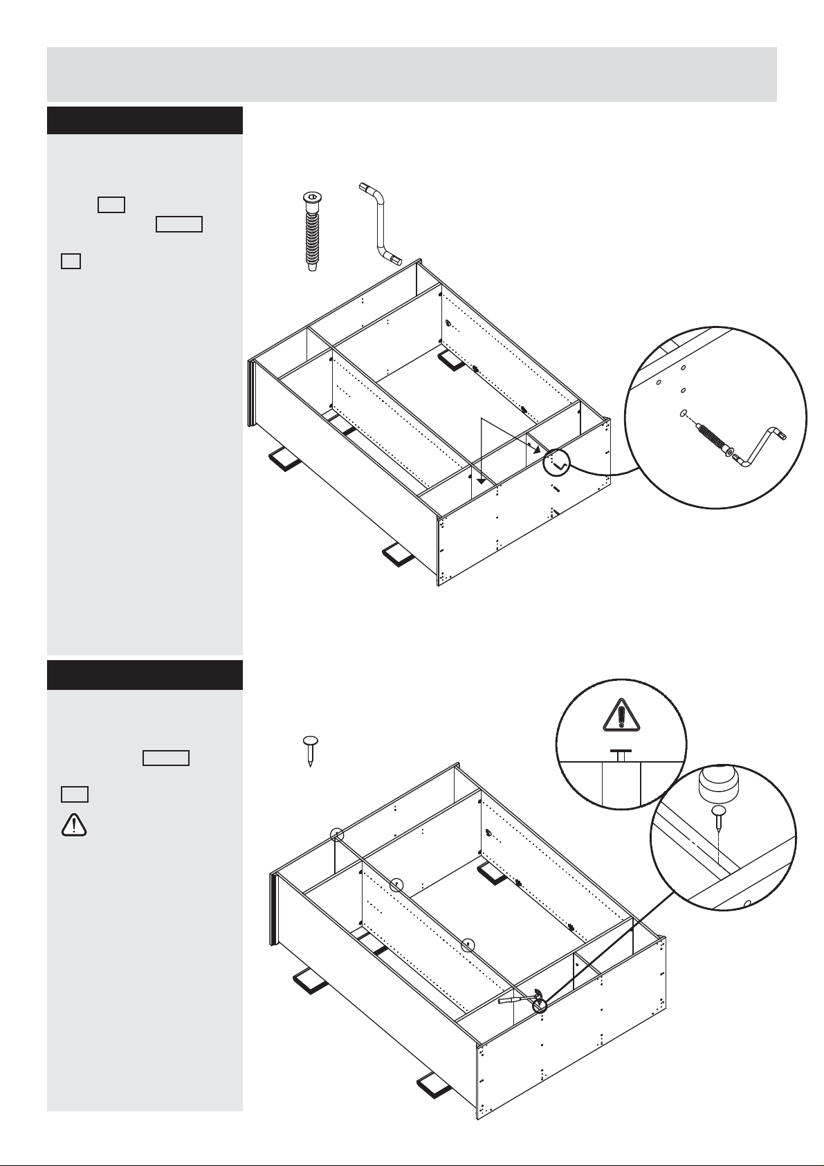
Attaching divider panel
Attach the divider
panel GA by inserting
connector bolt 25610 into
the holes of bottom panel
IC .
Connector bolt
# 25610 X3
Allen key
# 97642 X1
Tighten the connector
bolt with the allen key.
Step 16
Attaching nails
By using a hammer place
the big nails 23010 in
center of divider panel
GB .
See warning with
gap between nail and
middle panel.
IC
UB
UC
GB
GA
FA
UC
Fittings you will need for this step:
Big nail
# 23010 X4
IC
UB
UC
FA
UB
IC
FA
FA
GB
UC
UB
IC
14
Page 16
Assembly Instructions
2
5
p
c
s
Step 17
Fittings you will need for this step:
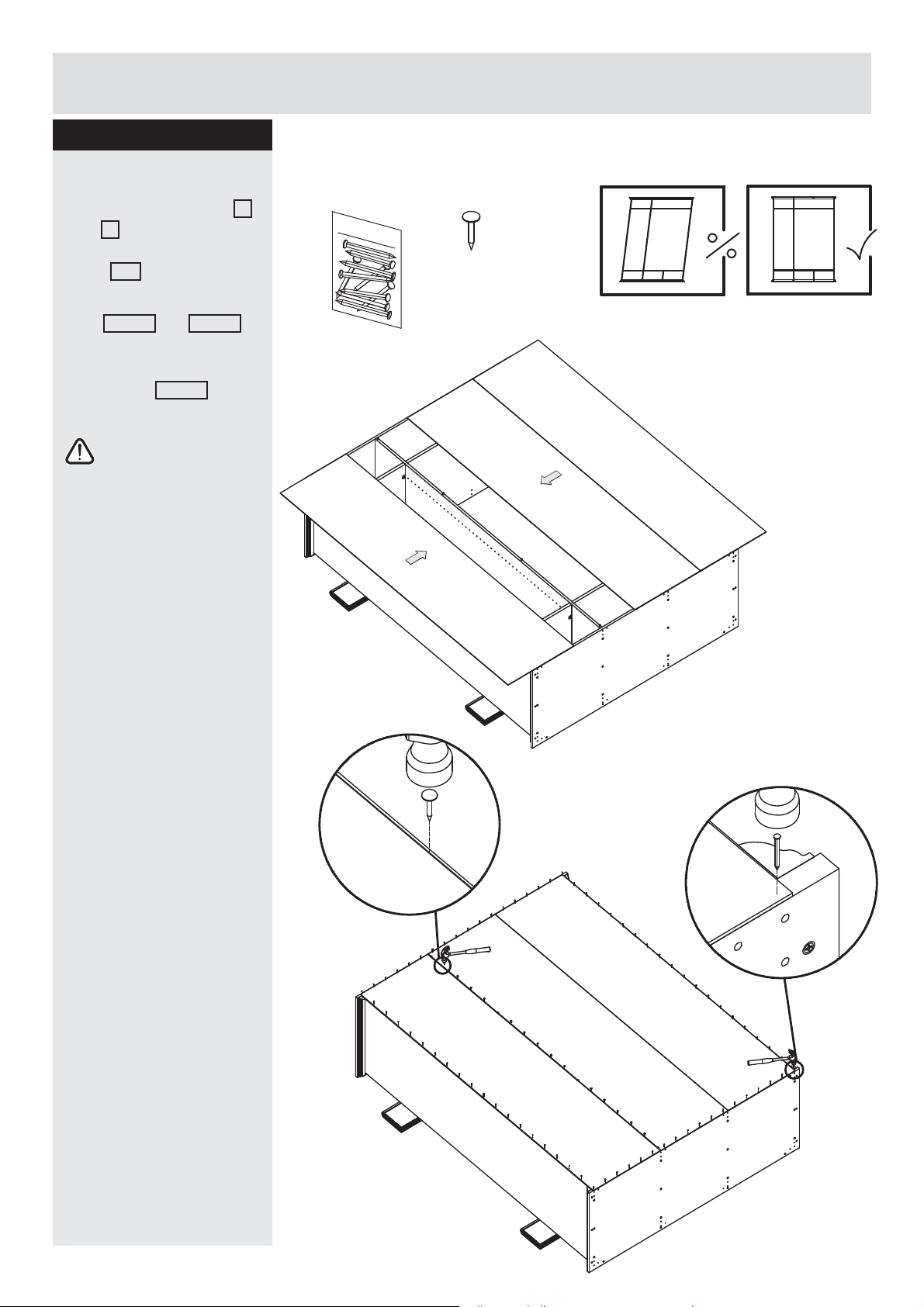
Fixing back panel
Slide the back panels J
and H as shown, so that
they meet in the center of
panel GB
Fix the back panels with
nails 23006 and 23010 .
Using nails 23006 to fi x
back panel.
Important:
The unit MUST be
square when the
back is attached.
Nail
# 23006 X3
J
Big nail
# 23010 X14
H
FA
IC
H
J
15
FA
IC
Page 17
Assembly Instructions
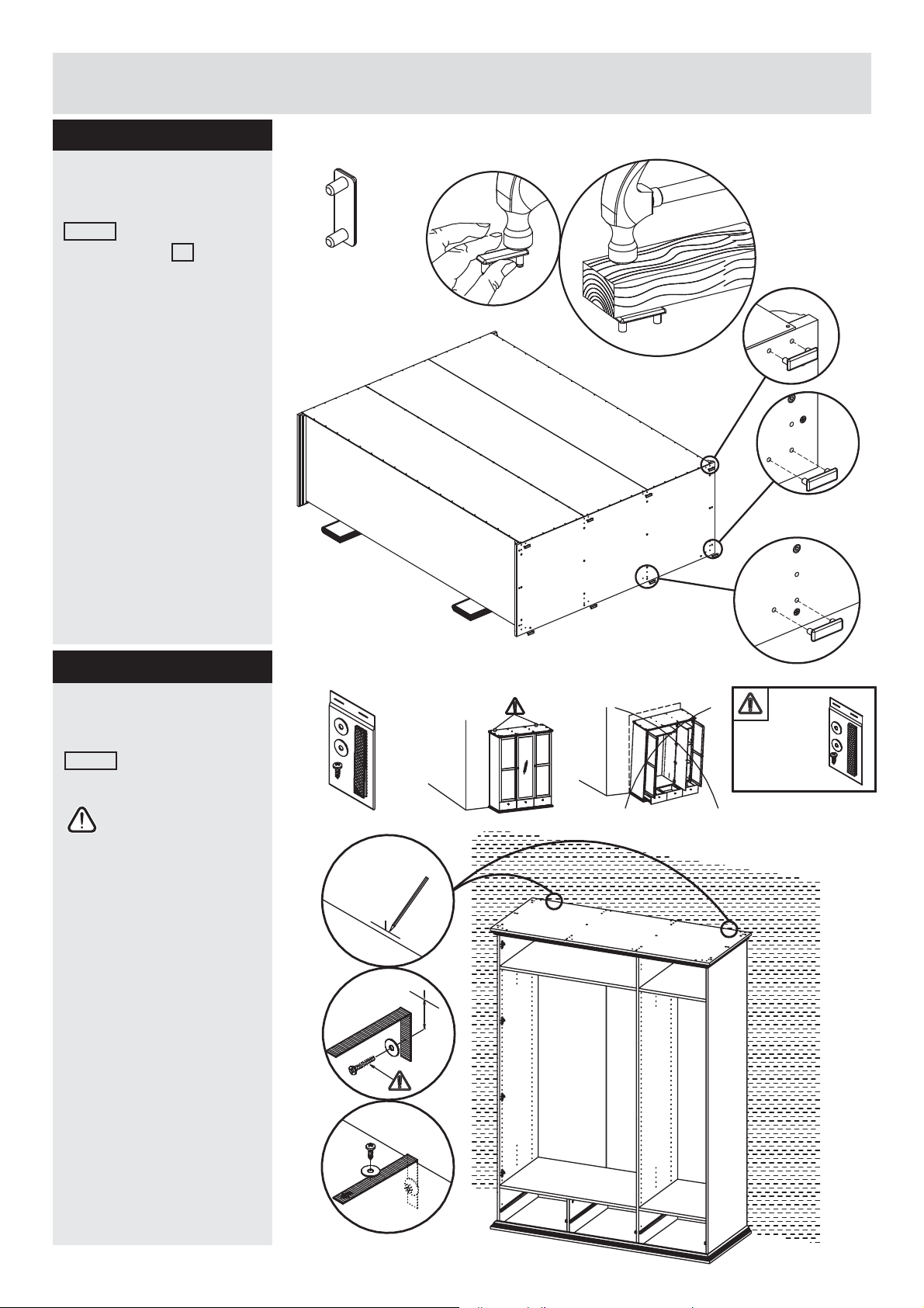
Step 18
Fittings you will need for this step:
Attaching back panels
Place the fl oor gliders
63008 in the holes of
bottom panel IA . Use a
wooden block between
hammer and fl oor glider.
Floor glider
#63008 X8
FA
H
J
Step 19
Fixing to wall
Fix unit to wall with strap
94009 .
The screw supplied
together with the
anti-topple bracket is
to be used only for
fi xing the
anti-topple bracket
to the furniture. In
addition to this you
will need to choose
a screw or fi tting
which is suitable for
securing the bracket
to the kind of wall
you have. If you are
unsure about what
type of screw to use
contact your local
hardware store.
Fittings you will need for this step:
Strap
# 94009 X2
UB
3 cm
FA
UB
IC
IC
UC
H
GB
FA
UC
IC
16
Page 18
Assembly Instructions
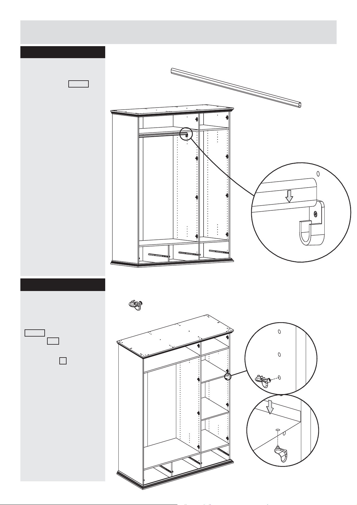
Step 20
Fittings you will need for this step:
Insert hanger
Insert hanger 72509
Hanger
# 72509 X1
Step 21
Attach the drawer
support
Press the shelf support
11042 in holes of side
panels FA .
Press down the loose
shelf panel T x2.
H
FA
Fittings you will need for this step:
Shelf support
# 11042 X8
UB
GB
FA
IC
UC
T
17
FA
H
UB
FA
GB
T
UC
IC
Page 19
Assembly Instructions
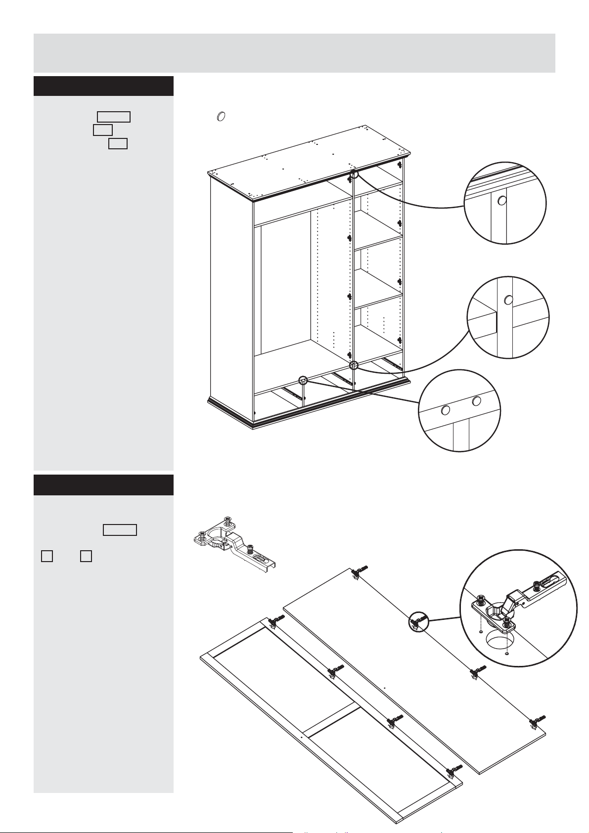
Step 22
Fittings you will need for this step:
Insert stop 96203 on
one shelf UB and
divider panel GB .
Stop
#96203 X4
IC
UC
UB
T
Step 23
Attach hinge
Press hinge 52291 into
the large holes on door
W and K . Drive the
pre-attached screws into
the holes on doors.
H
FA
GB
T
UC
UB
IC
Fittings you will need for this step:
Hinge
# 52291 X12
FA
K
(x2)
W
1918
Page 20
Assembly Instructions
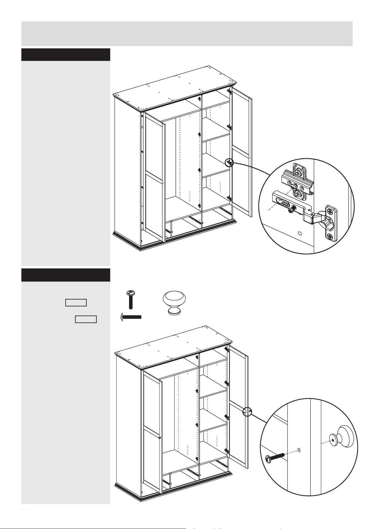
Step 24
Attach frame door
Slide the pivoting part
of the two hinges over
the hinge plates. Tighten
the screw on the hinge
plate until the door
is supported by the
hinges. The door can be
adjusted in and out by
pulling or pushing the
door then retightening
this screw
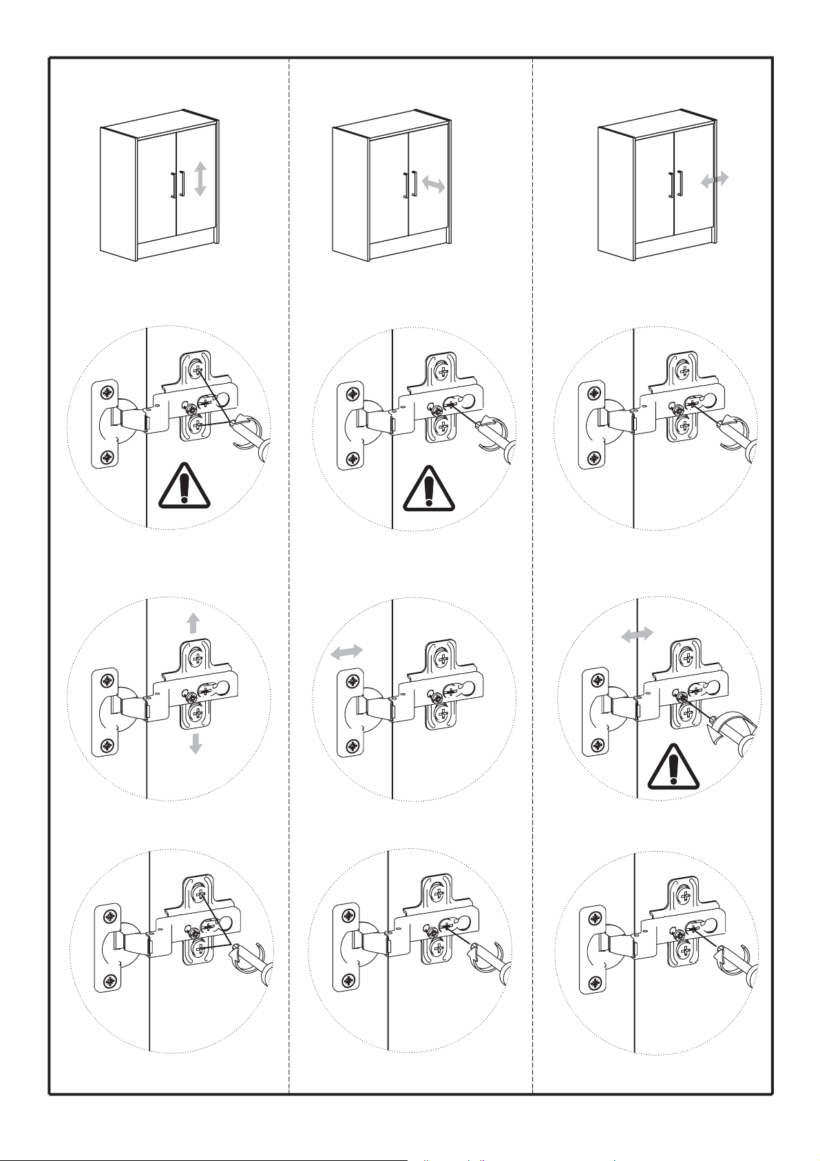
To adjust the door hinges
up and down: Loosen
the two large screws on
the hinge plate to adjust
the door up and down,
then retighten.
To adjust the doors left
or right, rotate the small
screw on the hinge in or
out.
K
FA
IC
UB
UB
UC
K
T
GB
T
UC
IC
Step 25
Attach door handle
Pass screw 26232
through the door then
into the handle 81040
and tighten.
Fittings you will need for this step:
FA
Screw
# 26232 X2
K
IC
UB
UB
Handle
# 81040 X2
GB
UC
T
T
UC
K
2019
IC
Page 21
Assembly Instructions
x
Step 26
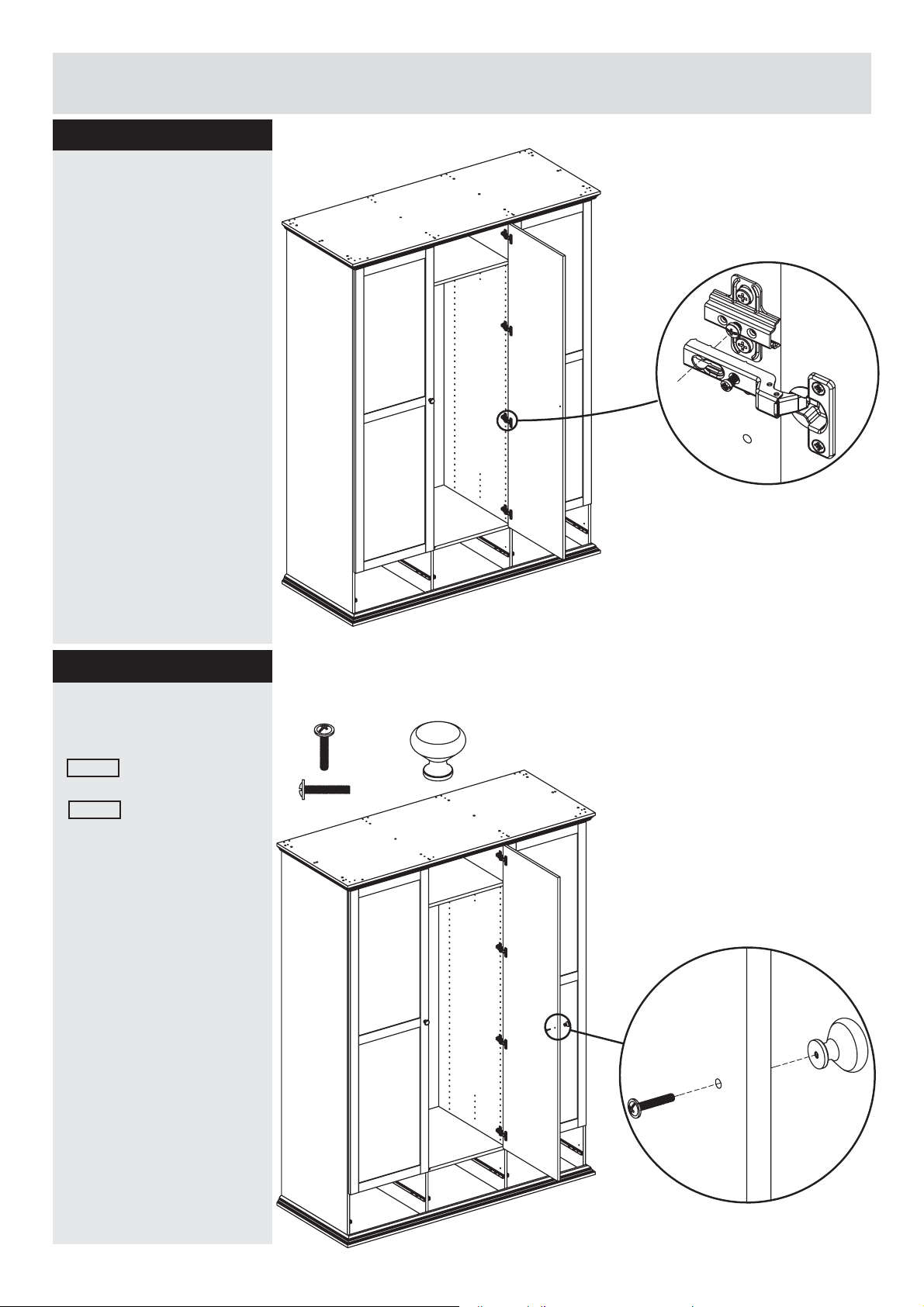
Attach mirror door
Slide the pivoting part
of the two hinges over
the hinge plates. Tighten
the screw on the hinge
plate until the door
is supported by the
hinges. The door can be
adjusted in and out by
pulling or pushing the
door then retightening
this screw
To adjust the door hinges
up and down: Loosen
the two large screws on
the hinge plate to adjust
the door up and down,
then retighten.
To adjust the doors left
or right, rotate the small
screw on the hinge in or
out.
FA
IC
K
UB
K
GB
UB
IC
W
Step 27
Attach door handle
Pass machine screw
26232 through the door
then into the handle
81040 and tighten.
Fittings you will need for this step:
IC
UB
Handle
# 81040 X1
GB W
FA
Machine screw
# 26232 X1
K
K
UB
IC
2120
Page 22
Assembly Instructions
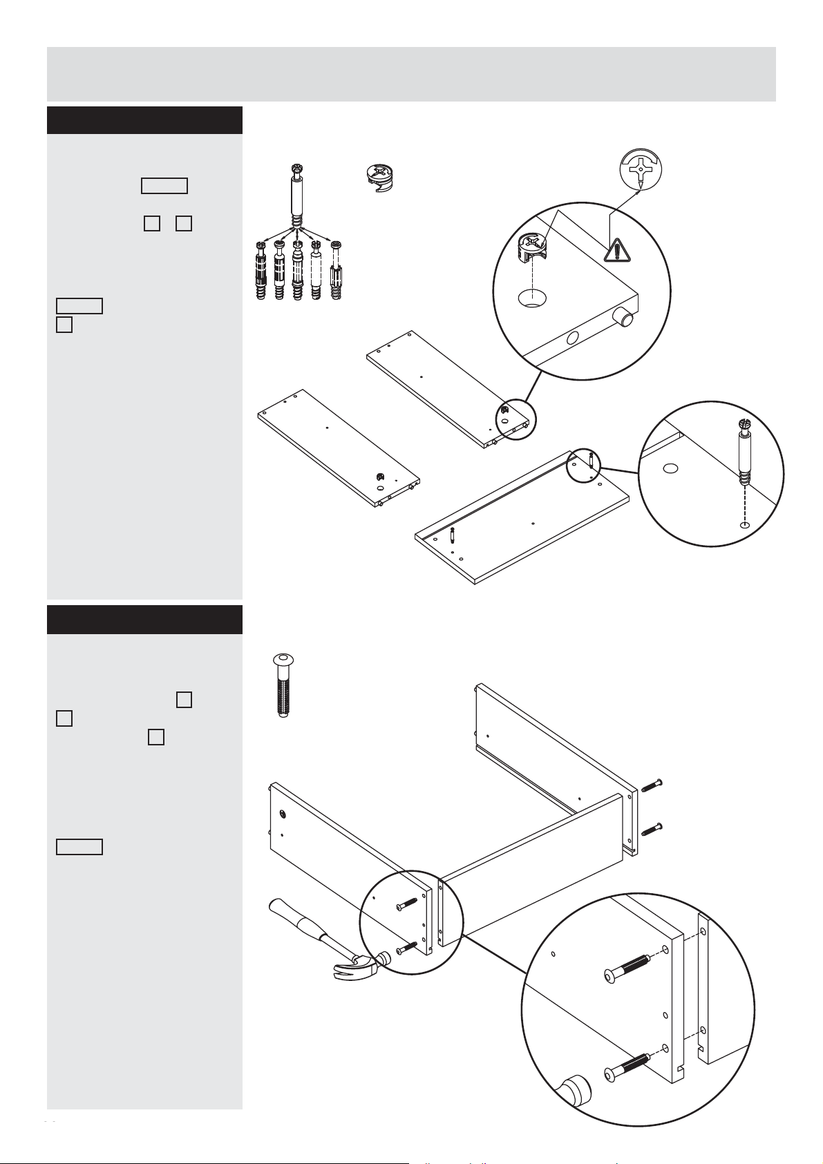
Step 28
Fittings you will need for this step:
Attaching drawers
Attach cam 31687 into
the holes in left and right
drawer side B + A .
Arrow facing the edge of
the panel.
Screw the cam bolt
31513 in the drawer front
E .
Cam bolt must be
screwed down fl ush.
Cam bolt
# 31513 X6
B
(x3)
Cam
# 31687 X6
A
(x3)
Step 29
Attaching drawer
Align holes at back of
the drawer sides B +
A with the holes on the
drawer back C .
Make sure the groove
is facing inside of the
drawer.
Tap drawer fasteners
20228 into place with a
hammer.
Fittings you will need for this step:
Drawer fastener
# 20228 X12
B
E
(x3)
A
C
21
22
x3
Page 23
Assembly Instructions
Step 30
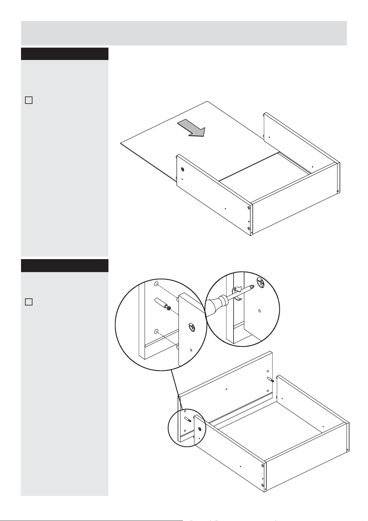
Attaching drawer
bottom
Press the drawer bottom
D smoothly in the
grooves (fi nished side
up).
Step 31
Attaching drawer front
Attach the drawer front
E by placing dowels and
cam bolt in the correct
holes. See the detail
drawing.
D
B
A
C
x3
Tighten the cams.
E
A
D
B
x3
C
22
23
Page 24
Assembly Instructions
Step 32
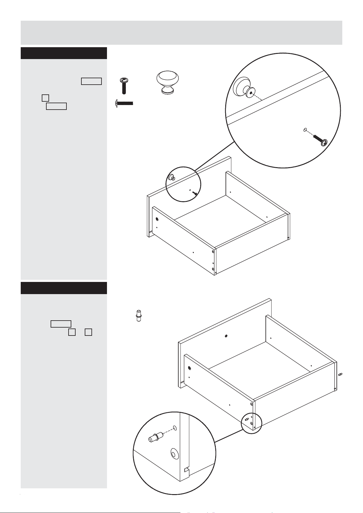
Fittings you will need for this step:
Attaching the drawer
Attach the handle 81040
in front of the drawer
front E . Use machine
screw 26232 to tighten
the handle.
Machine screw
# 26232 X3
Handle
# 81040 X3
E
A
Step 33
Attaching the drawer
Attach the drawer
support 11011 into holes
on side panel B + A .
D
B
Fittings you will need for this step:
Drawer support
# 11011 X6
B
C
E
A
D
C
2423
Page 25
Assembly Instructions
Step 34
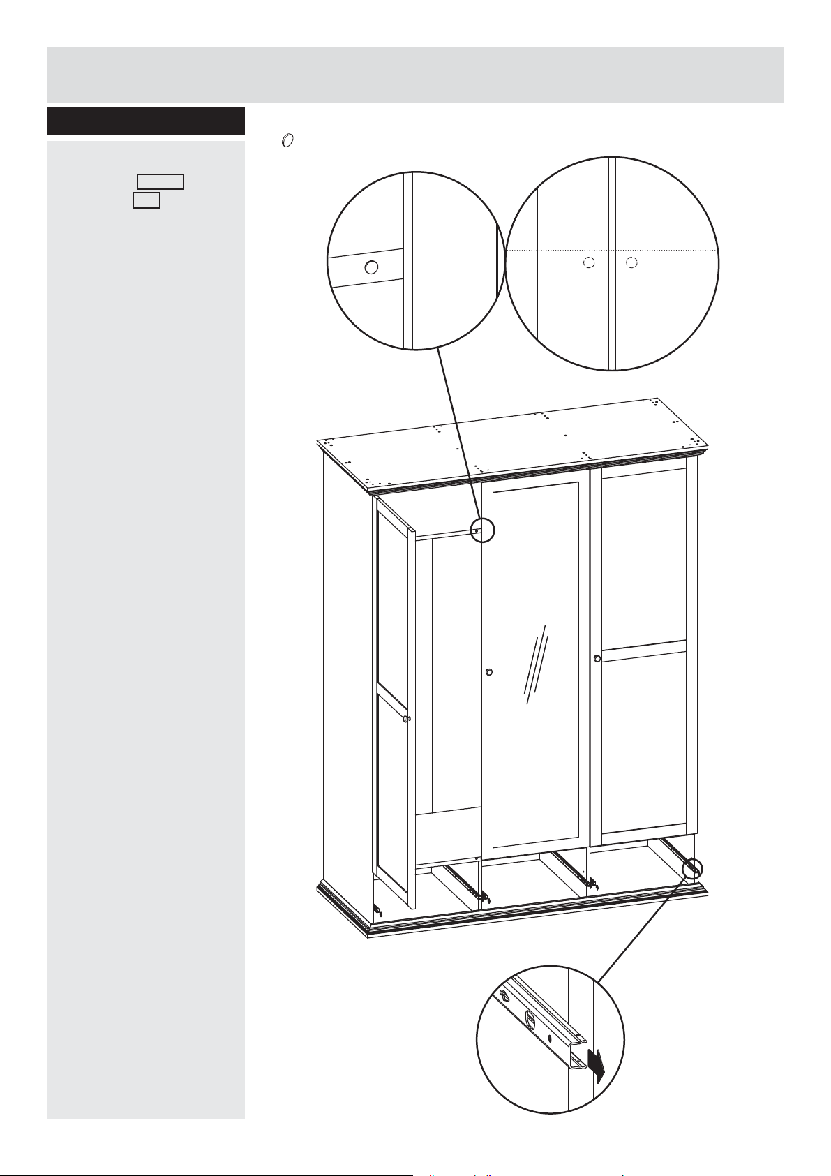
Insert stop
Insert stop 96203 on
one shelf UB .
Pulling out the runners
Pull out all the runners,
before placing drawers.
Fittings you will need for this step:
Stop
#96203 X2
IC
FA
IC
W
K
2524
Page 26
Assembly Instructions
Step 35
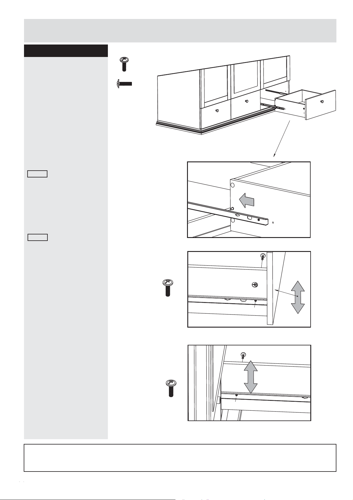
Attaching the drawers
1.
Place the drawer
between 2 rails.
See picture.
2.
Adjust front of drawer
up and down. Tight up
and fi x drawer to the rail
useing machine screw
26221 from inside the
drawer in both sides.
3.
Adjust back of drawer
up and down. Tight up
and fi x drawer to the rail
useing machine screw
26221 from inside the
drawer in both sides.
Fittings you will need for this step:
Machine screw
# 26221 X12
1.
2.
E
E
E
Drawer back
Repeat these step for each
of the remaining drawers.
Assembly is complete.
x2
Drawer front
3.
x2
Drawer back
If you need help or have damaged or missing parts, call the Customer Helpline:
Argos = 0345 6400800
2625
Page 27
1.
1.
1.
2.
3.
2.
3.
2.
3.
26
 Loading...