

Page 1
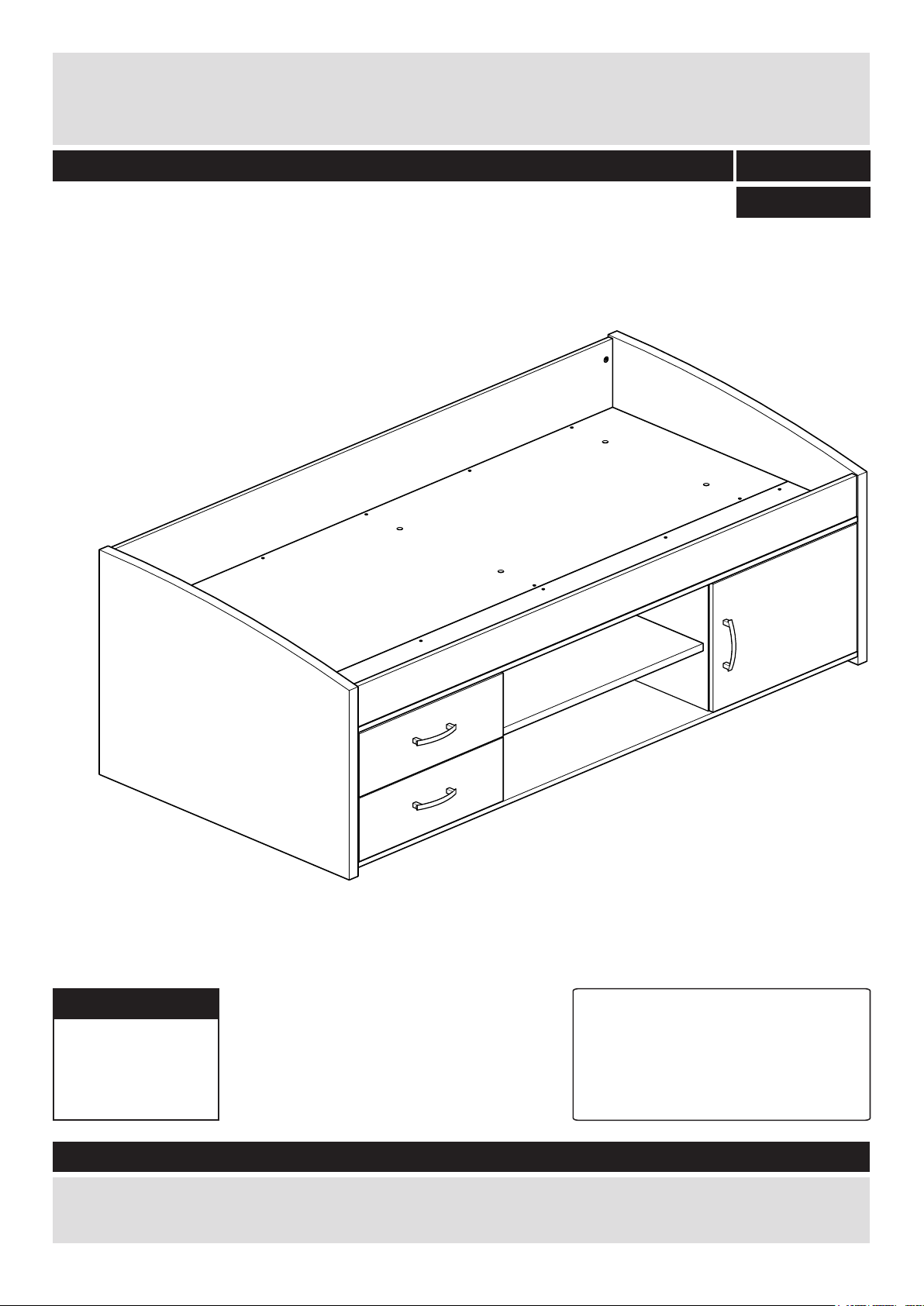
Yanniek Bed 90x190
DR82152
Assembly Instructions - Please keep for future reference
483/4124
459/7344
Dimensions
Width - 197.8 cm
Depth - 91.0 cm
Height - 67.0 cm
483/4124 OAK
459/7344 WHITE
Important – Please read these instructions fully before starting assembly
If you need help or have damaged or missing parts, call the
Argos = 03456 400 800
Tip : To prevent damage,
we recommend that you
build your unit on the
carton(s) it was packed in.
Customer Helpline:
Issue: 1 - 19/11/15
Page 2

Safety and Care Advice
Important – Please read these instructions fully before starting assembly
• Check you have all the
components and tools listed
on the following pages.
• Remove all fittings from the
plastic bags and separate them
into their groups.
• Keep children and animals
away from the work area, small
parts could choke if swallowed.
• Make sure you have enough
space to layout the parts before
starting.
• During assembly do not stand
or put weight on the product,
this could cause damage.
• Assemble the item as close
to its final position (in the same
room) as possible.
• Assemble on a soft level
surface to avoid damaging the
unit or your floor.
• Parts of the assembly will be
easier with 2 people.
• To reduce
the likelihood of
damaging your
product please
ensure that your
power drill is set on a low torque
setting.
• Assembly should be carried out
by a competent adult only.
• do not use this item if any
components are missing
or damaged.
• this item is suitable for childeren
from the age of 6.
Glue safety - Take care when using glue, please follow the advice below•
Skin contact: Remove
contamination by washing with
soap and water. This procedure
should also be followed prior to
eating and drinking.
Eye contact: Rinse immediately
with clean water for 15 minutes
and seek medical advice.
If swallowed: Seek medical
advice immediately.
Care and maintenance
• Only clean using a damp cloth
and mild detergent, do no use
bleach or abrasive cleaners.
Handy Hints
• Assemble all parts and bolts
loosely during assembly, only
once the product is complete
should you fully tighten the bolts
• From time to time check that
there are no loose screws on
this unit.
• Regularly check and ensure
that all bolts and fi ttings are
tightend properly.
• This product should not be
discarded with household waste.
Take to your local authority
waste disposal centre.
•
Note: if required the next
page can be cut out and used
as reference throughout the
assembly. Keep this page with
these instructions for future
reference.
1
Page 3
If you have damaged or missing components,
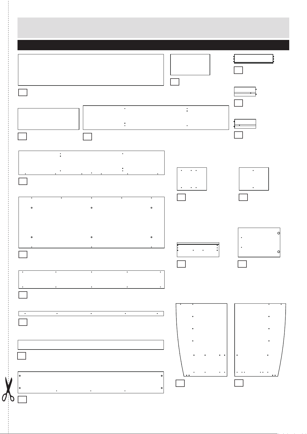
Components - Panels
call the Customer Helpline:
Please check you have all the panels listed below
Back
1
(1908 x 411 x 3 mm)
BO2686
Drawer base x 2
2
(516 x 280 x 3 mm)
BO3101
03456 400 800
Drawer back x 2
3
(506 x 120 x 12 mm)
LA1654
Left drawer side x 2
4
(280 x 120 x 12 mm)
LA1655
Shelf
6
(801 x 280 x 22 mm)
P1018
Storage top
8
(1910 x 315 x 15 mm)
P1020
Bedbase
9
(1910 x 670 x 18 mm)
P1021
Storage bottom
7
(1910 x 315 x 15 mm)
P1019
Storage side left
12
(387 x 299 x 15 mm)
P2695
Drawer front x 2
17
(550 x 189 x 15 mm)
P4753
Right drawer side x 2
5
(280 x 120 x 12 mm)
LA1656
Storage side right
13
(387 x 299 x 15 mm)
P2696
Door front
14
(550 x 382 x 15 mm)
P3716
Small bedbase
10
(1910 x 235 x 18 mm)
P1022
Plinth
11
(1900 x 60 x 28 mm)
P1876
Front panel
15
(1910 x 122 x 18 mm)
P4751
Rear panel
16
(1910 x 282 x 15 mm)
P4752
Headboard
18
(955 x 670 x 34 mm)
P8996
Footboard
19
(955 x 670 x 34 mm)
P8997
2
Page 4
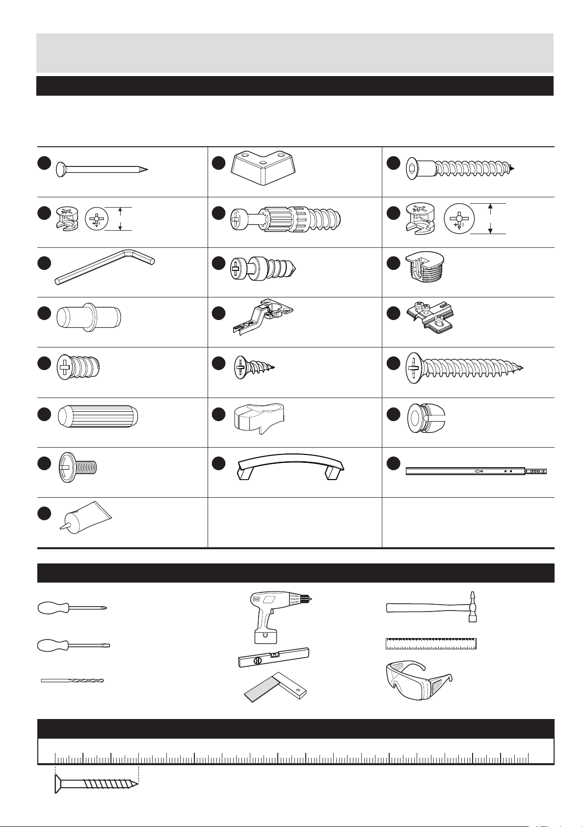
Components - Fittings
Please check you have all the fittings listed below
Note: The quantities below are the correct amount to complete the assembly. In some cases more fittings
may be supplied than are required.
A
Nail x 30
D
Locking nut x 4
12mm
(12x10mm)
G
Allen key x 1
(3mm)
J
Shelf support x 1
(5x15mm)
M
Drawer fixing screws x 8
P
FA1515
FK1010
FK1013
FK1201
FK1301
(6.3x10mm)
FK1411
B
Foot x 4
E
Locking screw x 16
(5x24mm)
H
Small locking screw x 6
K
Hinge door x 2
N
Pozi screw x 4
(4x12.5mm)
Q
FA1706
FK1011
FK10561
(5x11mm)
FK1240
FK1309
FK1415
C
Confirmat screw x 23
F
15mm
Large locking nut x 12
I
Connector x 6
(20x12mm)
L
Hinge back x 2
O
Chipboard screw x 36
R
FK1005
(5x40mm)
FK1012
(15x12mm)
FK1016
FK12641
FK1322
(4x30mm)
FK1800
Wooden dowel x 8
S
Screw x 4
(M4x9mm)
W
Glue x 1
Tools required
Phillips screwdriver
(medium & large)
Flatblade screwdriver
(medium)
7mm Suitable drill bit
(for use with wall plug)
(8x30mm)
FK1981
FA1510
Nail holder x 1
T
Shelf/door handle x 3
GR1957
(128mm)
Drill
Spirit level
Setsquare
Plug x 12
U
Runner x 4
0102030405060708090 100 110 120 130 140 150
0123456
Eye protection
(when using a
hammer or glue)
PM16951
Small
hammer
Ruler/tape
measure
Ruler - Use this ruler to help correctly identify the screws
0 5 10 15 20 25 30 35 40 45 50 55 60 65 70 75 80 85 90 95 100
The screws length is measured from the head to the point (30mm screw shown).
3
105
110 115 120 125 130 135 140 145 150 155 160 165 170
Page 5
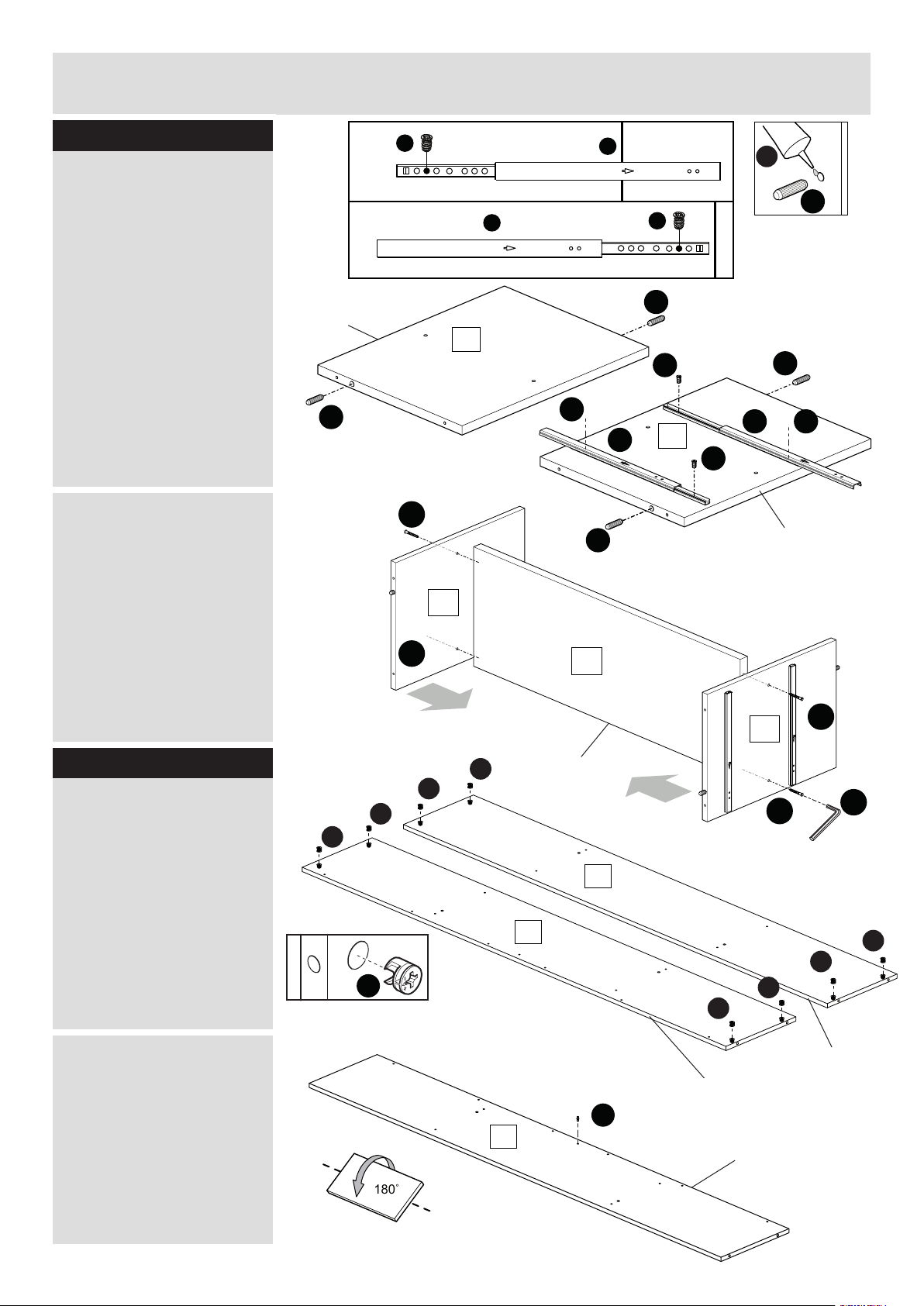
Assembly Instructions
180˚
Step 1
Preparing storage
sides
a: Insert 4 wooden dowels
P with a small amount of
glue W into the holes of
left @ and right storage
sides #.
Fix runners U on left storage
side @ as shown using
4 drawer fixing screws M.
Make sure the arrow on the
runner is pointing to the
finished front edge.
b: Attach left @ and right
storage sides # with 4
confirmat screws C to the
shelf 6 using allen key G.
a:
Finished
front edge
P
b:
1.
2.
M
U
13
M
U
M
P
M
U
12
M
U
W
P
P
M
C
P
Finished
front edge
Step 2
Assembling storage
unit
a: Insert 8 large locking
nuts F into storage bottom
7 and top 8 where shown.
Make sure the ‘arrow’
on the large locking nuts F
are pointing towards the
holes in the edges of 7
and 8.
b: Turn over the storage top
8 and insert shelf support
J.
a:
b:
13
C
Finished
front edge
F
F
F
F
8
F
8
6
C
C
G
F
F
Finished
front edge
12
7
F
F
Finished
front edge
J
Finished
front edge
Continued on next page.
4
Page 6

Assembly Instructions
Step 2 continued
c: Attach storage bottom
7 and top 8 with 8
confirmat screws C to the
storage sides @ and #
using allen key G.
Step 3
Inserting fittings
a: Insert 4 wooden dowels
P with a small amount of
glue W in the holes of
front panel %.
c:
a:
C
C
C
P
P
13
7
Finished
front edge
C
8
C
C
12
C
C
Finished
front edge
W
P
b: Insert 5 plugs R in
footboard (.
Screw 3 small locking
screws H and 6 locking
screws E in footboard (.
Followed by screwing 2
back hinges L in footboard
(.
b:
15
E
R
E
E
H
R
H
E
H
H
R
R
R
19
L
E
L
Finished
front edge
P
P
Finished
front edge
L
E
E
R
5
Page 7

Assembly Instructions
Step 4
Attaching panels
a: Use a screwdriver to
turn the 4 locking nuts F
in storage top 8 and
bottom 7 clockwise to
lock on footboard (.
a:
19
F
8
F
7
F
F
b: Put drop of glue W in the
2 holes of footboard (
before sliding them onto the
dowels of front panel %.
Make sure front panel % is
placed beneath shelf
support J as is shown.
b:
W
19
8
Finished
15
front edge
J
15
6
Page 8

Assembly Instructions
Step 5
Preparing panels
a: Attach plinth ! to
rear panel ^ with 5
confirmat screws C using
allen key G.
Insert 4 large locking
nuts F into rear panel ^
where shown.
Make sure the ‘arrow’
on F is pointing towards
the hole in the edge of
rear panel ^.
a:
F
C
F
C
Finished
front edge
C
C
F
16
C
11
F
F
b: Insert 7 plugs R in
headboard *.
Screw 3 small locking
screws H and 6 locking
screws E in headboard *.
Followed by attaching the
runners U with 4 drawer
fixing screws M.
Make sure the arrow on the
runner is pointing to the
finished front edge.
b:
1.
2.
U
M
H
E
E
M
U
M
R
R
M
U
U
H
R
R
M
R
E
M
R
E
E
E
H
R
18
E
R
H
Finished
front edge
7
Page 9

Assembly Instructions
Step 6
Assembling main body
a: Connect the rear panel
^ to the footboard (
and use a screwdriver to
turn the 2 locking nuts F.
Let another person hold
the rear panel ^ while
connecting the headboard
* to the rear panel ^,
storage top 8 and bottom
7.
Use a screwdriver to
turn the 6 locking nuts F.
a:
F
F
16
19
F
F
8
18
7
F
b: Fix the front panel % to
the storage top 8 with 6
confirmat screws C using
allen key G.
b:
F
F
15
C
C
8
C
C
F
C
C
8
Page 10

Assembly Instructions
90˚
Step 7
Fitting back panel
Attach back 1 to the back
of the storagebox with the
coloured surface facing the
inside of the unit using nails
A.
Use nail holder Q to hold
the nails vertical and at
correct distance as you
secure the back. The nails
should be spaced about
150 mm apart.
Attach the 4 feet B on the
storage bottom 7 using 12
chipboard screws O.
Note: there are no predrilled holes for the
chipboard screws O.
O
A
Q
19
A
A
A
A
A
A
O
O
O
O
O
O
B
A
A
A
A
O
A
A
1
A
A
O
O
O
O
O
A
A
A
A
A
A
A
B
B
A
18
A
A
A
A
A
B
B
7
A
Step 8
Assembling support
boards
a: Flip the unit from its
side with two persons.
Use 8 chipboard screws
O to attach small bedbase
0 to the storage top 8,
make sure to position
the small support board
against the front panel %.
Note: there are no predrilled holes for the
chipboard screws O.
O
a:
O
O
O
O
O
10
8
15
O
O
O
O
O
O
Continued on next page.
9
Page 11

Assembly Instructions
Step 8 continued
b: Place 6 connectors I
in the bedbase 9.
b:
I
9
I
I
I
I
I
I
c: Two persons are
needed for this step.
Place the bedbase 9,
with connectors I facing
downward, on the small
locking screws H on head* and footboard (.
Use 8 chipboard screws
O to attach the bedbase
9 to the plinth ! and
storage top 8.
Note: there are no predrilled holes for the
chipboard screws O.
c:
O
18
O
11
O
O
O
O
O
9
8
O
19
10
Page 12

Assembly Instructions
Step 9
Preparing the drawer
sides
a: Insert 2 small locking
nuts D into the holes on
drawersides 4 and 5.
Make sure the ‘arrow’ on D
is pointing towards the hole
in the edge of 4 and 5.
a:
2x
D
D
5
D
4
b: Put a drop of glue W in
the 6 holes of drawersides
4 and 5 before sliding
them onto the dowels of
drawerback 3.
Slide drawerbase 2 in the
grooves of the drawer-unit.
b:
2x
W
4
2
5
3
11
Page 13

Assembly Instructions
Step 10
Assembling drawer
a: Screw 2 locking screw E
into the holes shown on the
back of each
drawer front &.
Put drop of glue W in the
4 holes of the drawer front
& before sliding them
onto the dowels of
drawer sides 4 and 5.
Turn the drawer wrap
assembly over and push onto
the drawer front &. Use a
phillips or flatblade
screwdriver, that is a good fit,
to turn the small locking nut
D as far as it will go - more
than 1/2 turn.
a:
W
2x
E
3
5
2
4
E
17
E
b: Attach drawer handle T
on drawer front & as shown
using 2 chipboardscrews O.
b:
2x
5
O
3
4
O
T
17
12
Page 14

Assembly Instructions
Step 11
Preparing door
Position the 2 door hinges
K in the holes on the door
front $, fixate with 4 pozi
screws N.
Note: there are no predrilled holes for the
pozi screws N.
14
N
N
K
N
N
K
Step 12
Attaching door and
drawers
a: Follow the instructions on
the next page to assemble
the door and drawers.
a:
18
16
c
19
9
14
O
O
T
b
17
Continued on next page.
13
Page 15

Assembly Instructions
Step 12 continued
b: slot door hinges K onto
the back hinges L on
the footboard (.
Fix and position the door
by tightening the screws on
the back hinges L.
See ‘A Guide to - Hinges’
on page 15 for more
detailed instructions for
assembling the door or if
the door needs adjusting.
Attach door handle T on the
door front $ as shown
using 2 chipboardscrews O.
c: Fix the runners M on left
and right drawer side 4 and
5 as shown using screw S.
Repeat for the second
drawer.
b:
c:
L
K
19
14
O
T
O
M
2x
5
Assembly is complete.
18
S
4
M
4
M
2nd small
threaded hole
S
17
S
17
14
Page 16

A Guide to - Hinges
A Guide to - Hinges
Assemble
L
a: Hook hinge door
correctly to the hinge back
as shown.
b: Tighten screw to lock
hinges in position.
Note: The nick screw of
hinge door should slide
into the recess of hinge
back.
T
Hinge back x 6
b:
2
a:
K
U
Hinge door x 6
2
Adjustment
a: To move door up or
down: loosen screws
shown and move door to
suit.
Once door is aligned,
re-tighten.
b: To move door in or out:
loosen screw shown and
move door to suit.
Re-tighten screws.
C: To move door left or
right: loosen screw shown
and move door to suit.
Re-tighten screws.
a:
b:
c:
15
14
X12
 Loading...