

Page 1
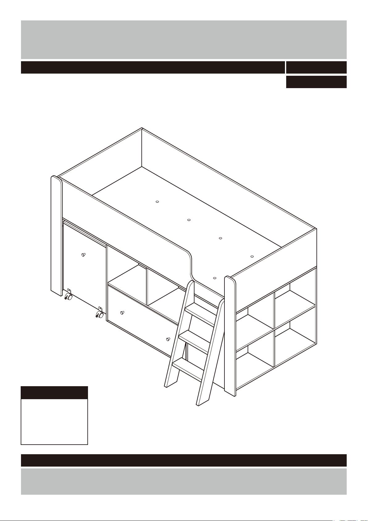
Qubrick Storage MidSleeper
Assembly Instructions
-
Please keep for future reference 461/8144
461/6517
Dimensions
Width - 204.5cm
Depth - 126cm
Height -111.5cm
-
Important
If you need help or have damaged or missing parts, call the Customer Helpline:
Argos = 0345 6400800
Please read these instructions fully before starting assembly
Version 1 Date: 20/10/15
Page 2

WARNING
IMPORTANT - READ CAREFULLY - RETAIN FOR FUTURE REFERENCE
• This bed complies the European Standard BS EN 747-1:2012+A1:2015 and BS EN 747-2:2012+
A1:2015.
• Follow the information on the warnings appearing on the upper bunk bed and do not remove the
warning label.
• Warning: “Children can become trapped between the bed and the wall. To avoid risk of serious
injury the distance between the top safety barrier and the wall shall not exceed 75mm or shall be
more than 230mm”.
• Warning: “Bunk beds and high beds can present a serious risk of injury from strangulation if not
used correctly. Never attach or hang items to any part of the bunk bed that are not designed to be
used with the bed, for example, but not limited to ropes, strings, cords, hooks, belts and bags”.
• Warning: “High beds and the upper bed of bunk beds are not suitable for children under six years
due to the risk of injury from fails”.
• Warning: Do not use the bunk bed/high bed if any structural part is broken or missing.
• The ventilation of the room is necessary in order to keep the humidity low and to prevent mould in
and around the bed.
• Be aware of the risk of injury of young children falling from the upper bunk bed.
• The top of the mattress shall be at least 160mm below the upper edge of guardrails.
• Recommended use only mattress which is L190 x W90 cm, 17cm or less in thickness on upper
bunk bed.
• Always use the recommended size mattress to prevent the likelihood of entrapment or falls.
• The use of water or sleep flotation mattress is prohibited.
• Prohibit more than one person on the upper bunk bed and do not allow horseplay on or under the
bed and prohibit jumping on the bed.
• Always use the ladder for entering and leaving the upper bunk bed.
• Use of a night light may provide added safety precaution for a child using the upper bunk bed.
• Periodically check and ensure that the guardrail, ladder, components and all assembly fastenings
are in their proper position and that care should be taken that no fittings are loose.
• Always follow the manufacturer’s instructions.
• The maximum child weight : 75 Kgs.
1
Page 3

Safety and Care Advice
Important – Please read these instructions fully before starting assembly
Important – Please read these instructions fully before starting assembly
• Check you have all the
components and tools listed on
the following pages.
• Remove all fi ttings from the
plastic bags and separate them
into their groups.
• Keep children and animals
away from the work area, small
parts could choke if swallowed.
• Make sure you have enough
space to layout the parts before
starting.
Care and maintenance
• Only clean using a damp cloth
and mild detergent, do no use
bleach or abrasive cleaners.
Handy Hints
• Do not use this item if any
components are missing or
damaged.
• During assembly do not stand
or put weight on the product,
this could cause damage.
• Assemble the item as close
to its fi nal position (in the same
room) as possible.
• Assemble on a soft level
surface to avoid damaging the
unit or your fl oor.
• From time to time check that
there are no loose screws on
this unit.
• During assembly children
should be kept away from the
product due to possible risk of
injury.
• Parts of the assembly will be
easier with 3~4 people.
• To reduce
the likelihood of
damaging your
product please
ensure that your
power drill is set on a low torque
setting.
• This product should not be
discarded with household waste.
Take to your local authority
waste disposal centre.
.
• Regularly check and ensure
that all bolts and fittings are
tightend properly.
IMPORTANT: RETAIN THESE INSTRUCTIONS FOR FUTURE REFERENCE
• Argos Ltd. MK9 2 NW. • This product is intended for
children in the age 6 or above.
• Maximum load: 75 kgs.
• Assembly of this product must
be carried out by a competent
adult.
Note: if required the next
page can be cut out and used
as reference throughout the
assembly. Keep this page with
these instructions for future
reference.
2
Page 4
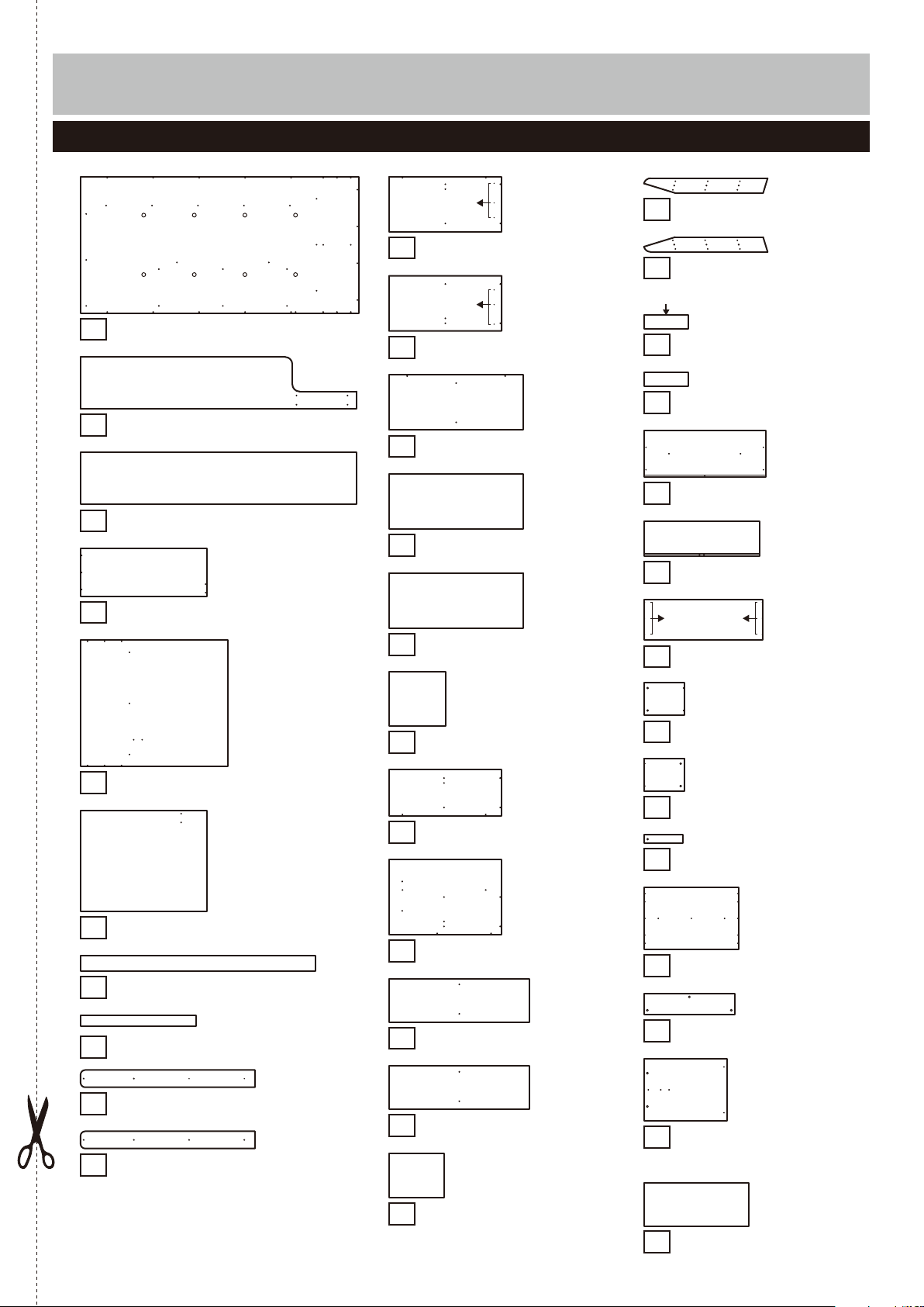
If you have damaged or missing components, call the
Components - Panels
Customer Helpline:
Please check you have all the panels listed below
Argos = 0345 6400800
Bed panel (193.6 x 95cm)
1
Front bed frame
Bed frame
Right panel
(192 x 36cm) 3
(95 x 36cm) 4
Pilot holes for
guidance only
Ladder right
22
(92.1 x 11.1cm)
11
Mid right
Pilot holes for
guidance only
Mid left
(192 x 36cm) 2
Mid shelf
Mid bottom
Mid back panel
(73.5 x 36cm)
(73.5 x 36cm)12
(87.7 x 36cm)13
(87.7 x 36cm) 14
(87.7 x 36cm)15
Ladder left
Unfinished back edge
Top ladder
Ladder x2
(33 x 10.2cm)25
Drawer front
Drawer back
Pilot holes for
guidance only
Drawer bottom
28
(92.1 x 11.1cm)23
(33 x 10.2cm)24
(87.1 x 33.6cm)26
(82.8 x 25cm)27
(85.2 x 28.6cm)
Left panel
Cube back panel
(111.2 x 95cm) 5
(91.9 x 73.5cm) 6
Back support panel
Left support panel
Front right panel
Front left panel
(111.2 x 11.1cm) 9
(111.2 x 11.1cm) 10
Drawer right
Mid support
16
(36 x 34.3cm)
29
Drawer left
Cube right
(73.5 x 30cm) 17
Drawer support
18
Cube left
(163.6 x 11cm)7
(74 x 7cm) 8
Cube shelf
20
Cube bottom
(73.5 x 49cm)
(91.9 x 28.4cm)19
(91.9 x 28.4cm)
Table top
Table support
34
Table side panel x2
(64 x 47.8cm)
(29 x 23.3cm)
(29 x 23.3cm)30
(27.7 x 6cm)31
(73.6 x 48.1cm)32
(70.3 x 16.5cm)33
21
Cube support x 2
(35.2 x 28.3cm)
Bottom back panel
(90.4 x 37cm)35
3
Page 5
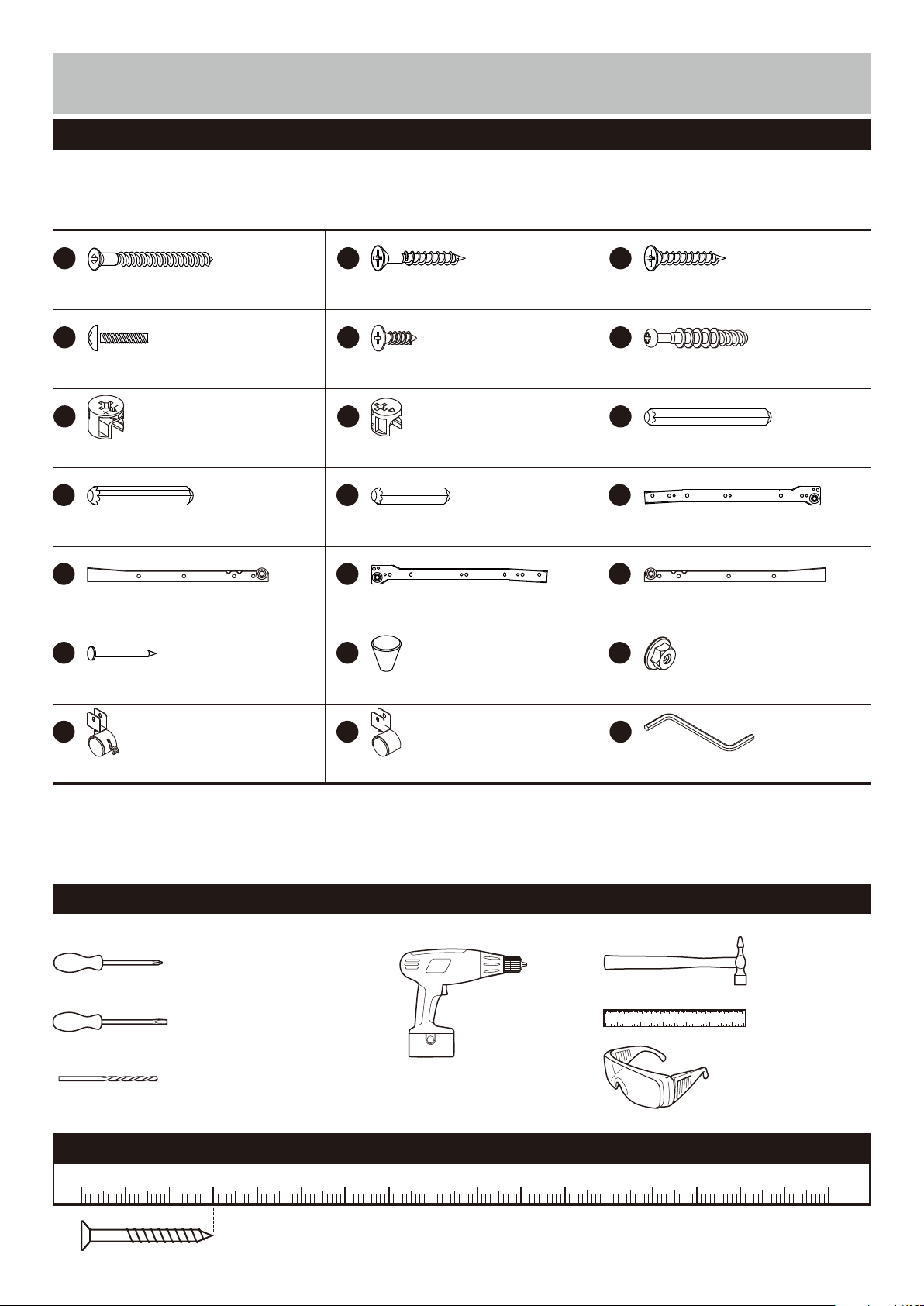
Components - Fittings
Please check you have all the fi ttings listed below
Note: The quantities below are the correct amount to complete the assembly. In some cases more fi ttings
may be supplied than are required.
A B C
50mm Screw x 107 25mm Screw x 230mm Screw x 9
D
24mm Screw x 4
G
E F
12mm Screw x 12
H
(This screw is included in
the runners bag)
12mm Locking nut x 515mm Locking nut x 7
J K L
M N O
Left outside runner x 1Right inside runner x 1 Left inside runner x 1
P Q R
Handle x 3Nail x 16 Nut x 4
S T
Castor x 2Front castor x 2
39mm Dowel x 12
I
50mm Dowel x 7
Right outside runner x 130mm Dowel x 1440mm Dowel x 6
U
Allen key x 1
Tools required
Phillips screwdriver
(medium & large)
Flatblade screwdriver
(medium)
Drill
7mm Suitable drill bit
(for use with wall plug)
Ruler - Use this ruler to help correctly identify the screws
105
0 5 10 15 20 25 30 35 40 45 50 55 60 65 70 75 80 85 90 95 100
The screws length is measured from the head to the point (30mm screw shown).
110 115 120 125 130 135 140 145 150 155 160 165 170
0 10 20 30 40 50 60 70 80 90 100 110 120 130 140 150
0 1 2 3 4 5 6
Small
hammer
Ruler/tape
measure
Eye protection
(when using a
hammer or glue)
4
Page 6
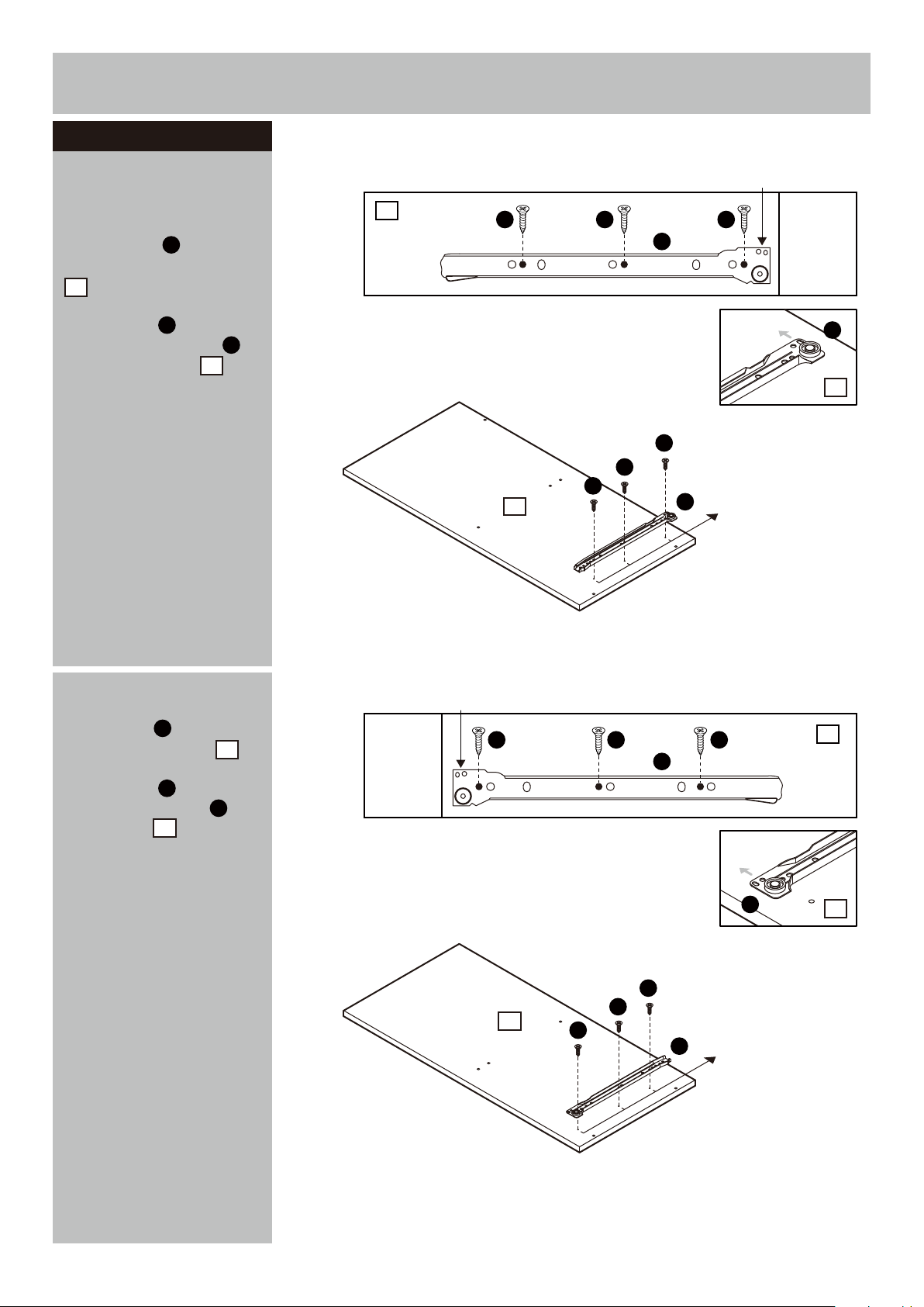
Assembly Instructions
Step 1
Attaching runners
a:
Position the Right out-
side runners in from
N
front edge of the Mid right
11
.
Use Screws to fix the
Right outside runner
onto the Mid right .
E
N
11
a:
11
E E
E
11
2 Holes upside
E
N
N
11
E
E
Pilot holes for
N
runner position
b:
Position the Left outside runner in from front
edge of the Mid left .
Use Screws to fix the
Left outside runner onto
the Mid left .
L
12
E
L
12
b:
2 Holes upside
E E E
12
E
E
12
L
L
E
L
Pilot holes for
runner position
12
5
Page 7

Assembly Instructions
Step 2
Fitting the middle
shelves
a:
Use 2 Screws by
Allen key to fix the Mid
support onto the Mid
shlef .
U
16
13
Insert Dowels into Mid
13
shlef .
b:
Use 2 Screws by
Allen key to fix the Mid
U
back panel onto the
Mid shlef .
13
A
K
A
15
a:
b:
Unfinished
back surface
Unfinished
16
back edge
13
K
U
A
13
A
Unfinished back surface
A
K
13
A
15
U
c:
Use 8 Screws by
Allen key to fix the
Mid right and Mid left
12 13
onto the Mid shlef
U
11
and Mid bottom .
A
14
c:
15
A
13
A
A
A
A
13
14
12
Unfinished
back edge
A
A
A
11
A
A
Unfinished
back surface
U
11 12
A
6
Page 8

Assembly Instructions
Step 3
Fixing bottom back
panel
Attach Bottom back panel
35
using nails .
Important:
The unit MUST
be ‘square’ when
back is attached.
P
Step 4
Fixing 4 cubes
a:
Insert Dowels into
the Cube shelf .
K
19
a:
a:
21
15
35
11
Unfinished back edge
14
P
Unfinished
back surface
I
K
19
Position the
21
onto the
using Dowels .
b:
Use 2 Screws by
Allen key to fix the Cube
bottom onto the Cube
support
Cube support
Cube
U
20
21
.
shelf
I
A
19
b:
I
Unfinished back edge
19
I
K
21
20
A
U
Unfinished
back edge
19
21
Continued on next page.
7
20
A
Unfinished
bottom surface
A
Page 9

Assembly Instructions
Step 4 - continued
c:
Carefully locate the
Cube back panel onto
6
the unit.
Fasten 12 Screws by
Allen key to fix Cube
right and Cube left
U
17 18
A
onto the Cube back panel
6
, Cube shelf and
Cube bottom .
19
20
c:
A
A
A
18
6
20
1917
A
A
A
A
U
A
17 18
A
A
A
A
A
Step 5
Fitting the ladder
a:
Insert Dowels into
the Top ladder and
Ladder .
b:
25
Fasten 12 Screws
by Allen key to fix Ladder
22
right and Ladder left
23
onto the Top ladder
and Ladder .
J
24
A
U
24
25
a:
b:
J
24
J
J
25
J
X 2
22 23
A
A
A
24
U
A
Continued on next page.
25
A
A
A
23
25
22
8
Page 10

Assembly Instructions
Step 5 - continued
c:
With help, upright down
the cube unit.
c:
18
Use 2 Screws by Allen
U
key to fix Top ladder
24 18
onto the Cube left .
A
A
U
A
A
6
24
18
d:
Use 2 Screws by
Allen key to fix Mid right
11 18
onto the Cube left .
U
A
d:
11
A
U
6
11
A
18
A
9
Page 11

Assembly Instructions
Step 6
Fitting the left panel
Note: It would be useful
to ask someone to help
you at this stage.
Use 4 Screws by Allen
U
key to fix the Back
support panel onto the
Left panel and Cube
back panel .
Insert Dowels into the
Cube right and Cube
18
left .
A
7
5
6
I
17
I
I
17
6
7
A
5
A
I
18
I
I
Step 7
Fitting the bed panel
a:
Use 5 Screws by
Allen key to fix the
U
Right panel onto Front
bed frame and Bed
frame .
2
3
A
4
a:
5 6
A
U
A
4
2
A
A
A
Continued on next page.
3
4
A
U
10
Page 12

Assembly Instructions
Step 7 - continued
b:
Use 3 Screws by
Allen key to fix the Left
U
support panel onto the
Bed panel .
c:
Use 16 Screws by
Allen key to fix the Bed
panel onto the Front
bed frame , Bed frame
1
U
1
2
and Right panel .
A
8
A
43
b:
c:
A
1
A
A
8
U
A
1
A
Continued on next page.
11
1
4
2
3
1
A
U
Page 13

Assembly Instructions
Step 7 - continued
d:
Upside down Bed
panel carefully.
Use 18 Screws by Allen
key to fix the Bed panel
U
1
onto the unit.
A
d:
A
3
2
1
6
7
15
e:
Use 9 Screws by
Allen key to fix the Left
panel onto the unit.
U
5
Use 4 Screws by Allen
key to fix the Ladder
U
22
right and Ladder left
23
onto the unit.
A
A
e:
5
1
A
U
4
3
A
1
A
A
A
A
5
A
A
A
A
2
A
22
23
25
A
U
12
Page 14

Assembly Instructions
Step 8
Fitting the front panels
Use 6 Screws by Allen
key to fix the Front right
U
panel and Front left
panel onto the unit.
9
10
A
109
A
U
Use 2 Screws to fix the
Front right panel onto
the Cube left .
C
9
18
4
3
A
1
A
9
18
C
C
C
20
9
C
2
5
A
A
A
10
A
18
Step 9
Drawer assembly
a:
Screw Locking pins
into the Drawer front .
Note:
Insert locking pins
as far as shown.
Do not over tighten.
Continued on next page.
13
26
a:
F
F
F
F
26
F
F
F
Page 15

Assembly Instructions
Step 9
b:
Fix Drawer right ,
Drawer support and
Drawer left onto Drawer
front .
Insert 5 Locking nuts
into the Drawer right ,
Drawer support and
Drawer left panel .
- continued
29
31
30
26
H
29
31
30
Use a screwdriver to turn
Locking nuts clockwise
H
to lock.
b:
H
H
30
31
29
H
H
26
H
H
c:
Carefully slide the
Drawer bottom into the
28
grooves.
d:
Position the Drawer
27
back onto the unit
using Screws .
B
c:
d:
Unfinished back surface
28
31
29
B
B
B
27
Continued on next page.
28
31
B
B
29
14
Page 16

Assembly Instructions
Step 9
e:
Use Screws to fix the
Right inside runner and
Left inside runner onto
- continued
E
M
O
the unit.
f:
Attach Handles using
Screws .
B
Q
e:
f:
E
O
E
M
E
E
29
28
26
B
E
E
Step 10
Inserting drawer
Slide the drawer fully onto
runners.
B
30
26
Q
Q
15
Page 17

Assembly Instructions
Step
Fitting the table
a:
into the Table side panel
34
.
Note:
as far as shown.
Do not over tighten.
a:
the Table side panel .
b:
the Table support .
11
Screw Locking pins
Insert locking pins
Insert Dowels into
Insert Dowels into
F
K
34
K
33
a:
b:
F
F
K
K
K
34
X 2
K
K
33
K
c:
Carefully locate the
Table side panel onto
the Table support .
Insert 2 Locking nuts
into the Table support .
Use a screwdriver to turn
Locking nuts clockwise
to lock.
34
33
G
33
G
c:
K
G
G
34
G
33
Continued on next page.
34
16
Page 18

Assembly Instructions
Step
d:
into the Table top .
Note:
11 - continued
Screw Locking pins
32
Insert locking pins
as far as shown.
Do not over tighten.
F
d:
F
F
F
F
F
F
32
e:
Carefully locate the
Table top onto the unit.
Insert 5 Locking nuts
32
G
into the Table side panel
34 33
and Table support .
Use a screwdriver to turn
Locking nuts clockwise
G
to lock.
e:
G
33
G
G
34
32
G
G
G
34
Continued on next page.
17
Page 19

Assembly Instructions
Step
f:
Screws .
Use Screw and Nut
to fix the Front castors
and Casters onto the
11 - continued
Attach Handle using
B
Q
D
T
R
S
unit.
The Front castors
Note:
S
feature a locking arm.
We recommend you lock
the castors when you have
finally positioned the unit
in place.
f:
34
B
34
Q
R
D
S
D
D
R
S
R
S
R
R
D
T
D
T
D
R
T
g:
Slide the table fully into
the unit.
g:
32
18
Page 20

Assembly Instructions
Step 12
Finishing the unit
Note:
to ask someone to help
you at this stage.
With help, place the unit
in the intended position.
It would be useful
Warnung:
Be aware of the
danger of young
children under six
years old falling
from the upper
bunk. Top bunk
beds are not
recommended for
children under six
years old.
Complies BS EN
747-1:2012+
A1:2015 and BS
EN 747-2:2012+
A1:2015.
Assembly is complete.
If you need help or have damaged or missing parts, call the Customer Helpline:
Argos = 0345 6400800
19
 Loading...