

Page 1
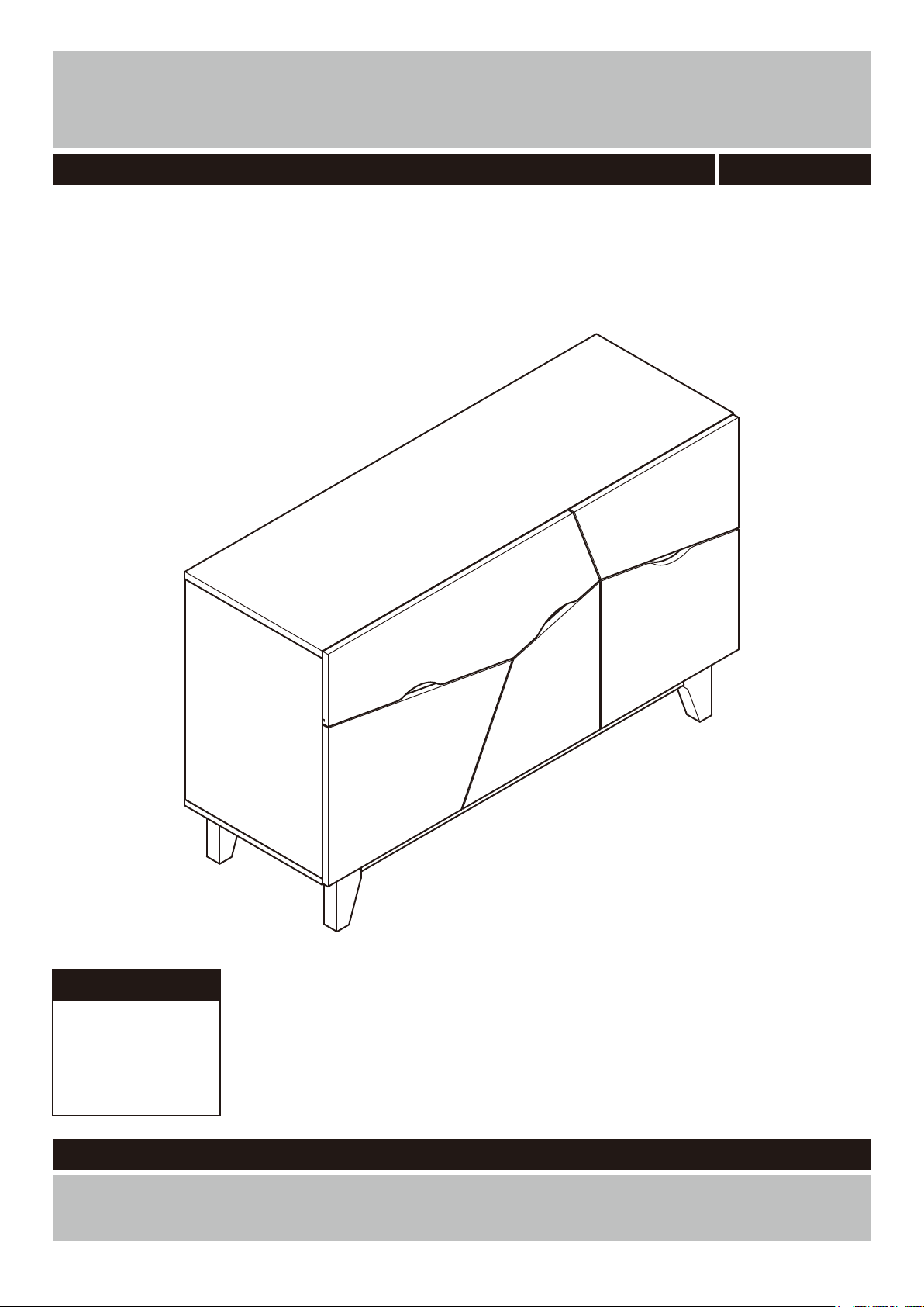
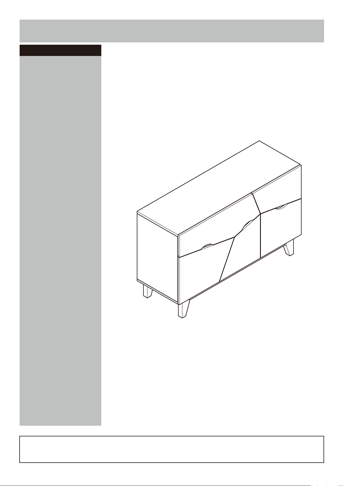
Multicoloured Sideboard
Assembly Instructions
-
Please keep for future reference
453/4785
Dimensions
Width - 120cm
Depth - 42cm
Height - 74cm
Important
-
-
Please read these instructions fully before starting assembly
If you need help or have damaged or missing parts, call the Customer Helpline:
Argos = 0345 6400800
Version 1 Date: 22/09/15
Page 2
Safety and Care Advice
Important – Please read these instructions fully before starting assembly
• Check you have all the
components and tools listed on
the following pages.
• Remove all fi ttings from the
plastic bags and separate them
into their groups.
• Keep children and animals
away from the work area, small
parts could choke if swallowed.
• Make sure you have enough
space to layout the parts before
starting.
Care and maintenance
• Only clean using a damp cloth
and mild detergent, do no use
bleach or abrasive cleaners.
Handy Hints
• During assembly do not stand
or put weight on the product,
this could cause damage.
• Assemble the item as close
to its fi nal position (in the same
room) as possible.
• Assemble on a soft level
surface to avoid damaging the
unit or your fl oor.
• Parts of the assembly will be
easier with 2 people.
• From time to time check that
there are no loose screws on
this unit.
• To reduce
the likelihood of
damaging your
product please
ensure that your
power drill is set on a low torque
setting.
• This product should not be
discarded with household waste.
Take to your local authority
waste disposal centre.
• Regularly check and ensure
that all bolts and fi ttings are
tightend properly.
Note: if required the next
page can be cut out and used
as reference throughout the
assembly. Keep this page with
these instructions for future
reference.
1
Page 3
If you have damaged or missing components, call the
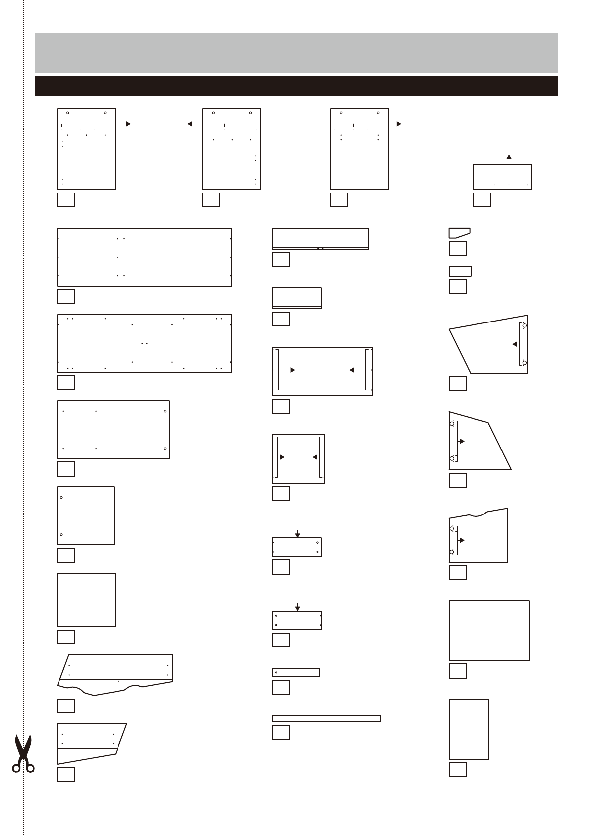
Components - Panels
Customer Helpline:
Please check you have all the panels listed below
Argos = 0345 6400800
Pilot holes for
guidance only
Left panel
1
(39.9 x 55.6cm)
Top panel
5
Bottom panel (120.1 x 40cm)
6
Left shelf
7
(120.1 x 40cm)
(76.4 x 39.8cm)
Right panel
2
(39.9 x 55.6cm)
3
Large drawer back
12
(66.6 x 14.5cm)
Small drawer back
13
(33.9 x 14.5cm)
Pilot holes for
guidance only
Large drawer bottom
14
(69 x 33.6cm)
Pilot holes
for
guidance
only
Small drawer bottom
15
(36.3 x 33.6cm)
Pilot holes for
guidance only
Middle right panel
(39.9 x 55.6cm)
Pilot holes for
guidance only
Middle panel
4
(39.8 x 17.4cm)
Leg x 4
20
Bottom support
21
(7 x 15cm)
Pilot holes for
guidance
Left door panel
22
(53.9 x 40.1cm)
Pilot
holes
for
guidance
only
Middle door panel
23
(40.1 x 37.4cm)
(7 x 15cm)
only
Right shelf
8
Middle left panel
9
Large drawer front (79.4 x 28cm)
10
Small drawer front
11
(38.8 x 39.8cm)
(39.8 x 36.6cm)
(47.9 x 28cm)
Finished front edge
Drawer left x 2
16
(34 x 12.8cm)
Finished front edge
Drawer right x 2
17
(34 x 12.8cm)
Drawer support
18
(32.7 x 6cm)
Front bottom panel x 2
19
(95.4 x 4.5cm)
Pilot
holes for
guidance
only
Right door panel
24
(40.1 x 37.4cm)
Large back panel
25
(78.4 x 58.6cm)
Small back panel
26
(41 x 58.6cm)
2
Page 4
Components - Fittings
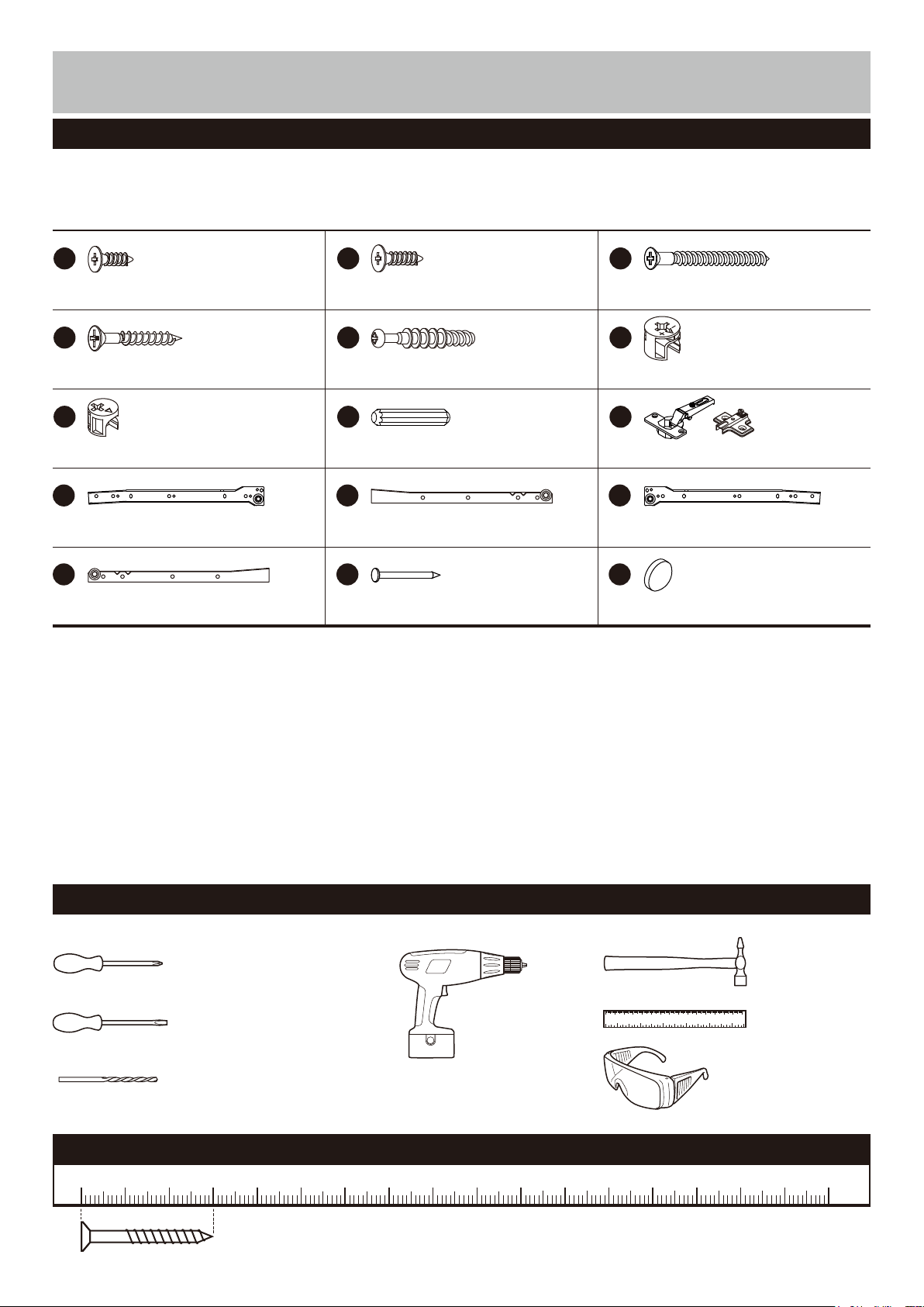
Please check you have all the fi ttings listed below
Note: The quantities below are the correct amount to complete the assembly. In some cases more fi ttings
may be supplied than are required.
A B C
(This screw is included in
the runners bag)
(This screw is included in
the door hinges bag)
12mm Screw x 24 50mm Screw x 3015mm Screw x 24
D
30mm Screw x 10
G
E F
39mm Locking pin x 19
H
30mm Dowel x 1112mm Locking nut x 9
J K L
M N O
Nail x 30Left inside runner x 2 Door pad x 3
15mm Locking nut x 10
I
Door hinge x 6
Left outside runner x 2Right inside runner x 2Right outside runner x 2
Tools required
Phillips screwdriver
(medium & large)
Flatblade screwdriver
(medium)
Drill
7mm Suitable drill bit
(for use with wall plug)
Ruler - Use this ruler to help correctly identify the screws
0 5 10 15 20 25 30 35 40 45 50 55 60 65 70 75 80 85 90 95 100
The screws length is measured from the head to the point (30mm screw shown).
3
105
Small
hammer
0 10 20 30 40 50 60 70 80 90 100 110 120 130 140 150
0 1 2 3 4 5 6
Ruler/tape
measure
Eye protection
(when using a
hammer or glue)
110 115 120 125 130 135 140 145 150 155 160 165 170
Page 5
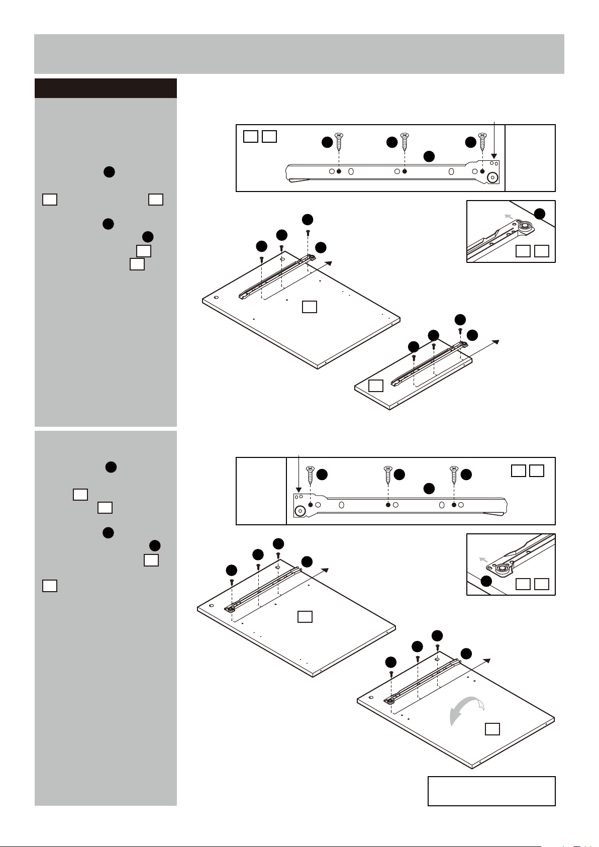
Assembly Instructions
Step 1
Attaching runners and
hinges
a:
Position the Left out-
side runners in from
J
front edge of the Left panel
2 2
and Middle panel .
Use Screws to fix the
Left outside runners
onto the Left panel
and Middle panel .
A
J
2
4
a:
2 4
A
2 Holes upside
A A
J
A
A
J
Pilot holes for
runner position
2
A
A
4
A
J
42
A
Pilot holes for
runner position
J
b:
Position the Right out-
side runners in from
L
front edge of the Right
panel and Middle
right panel .
Use Screws to fix the
Right outside runners
onto the Right panel
1
3
A
L
1
and Middle right panel
3
.
b:
2 Holes upside
A A A
L
A
A
A
1
L
Pilot holes for
runner position
L
A
A
A
L
Pilot holes for
runner position
3
31
31
Continued on next page.
Note: Repeat runner fixing on
reverse side.
4
Page 6
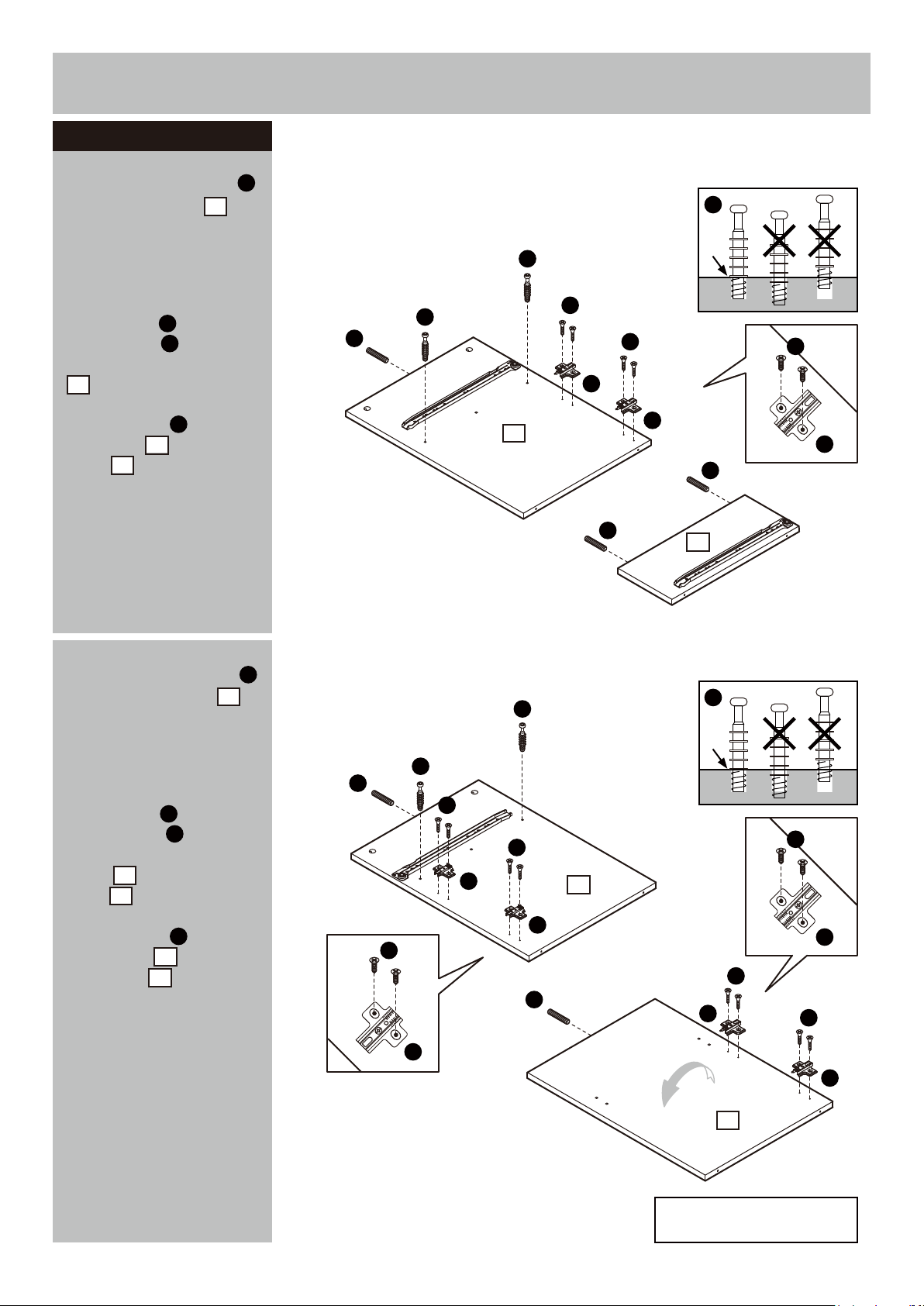
Assembly Instructions
Step 1 - continued
c:
Screw Locking pins
into the Left panel .
E
2
Note:
Insert locking pins
as far as shown.
Do not over tighten.
Use Screws to fix the
Door hinges ‘back
B
I
plates’ onto the Left panel
2
.
Insert Dowels into the
Left panel and Middle
panel .
4
H
2
c:
E
E
E
H
2
B
B
I
I
H
H
4
B
I
d:
Screw Locking pins
into the Right panel .
E
1
Note:
Insert locking pins
as far as shown.
Do not over tighten.
Use Screws to fix the
Door hinges ‘back
B
I
plates’ onto the Right
1
panel
panel .
Insert Dowels into the
Right panel and Middle
right panel .
and Middle right
3
H
1
3
d:
E
E
H
B
B
I
B
I
1
I
H
E
B
I
B
I
3
B
I
Note: Repeat door hinge fixing
on reverse side.
5
Page 7
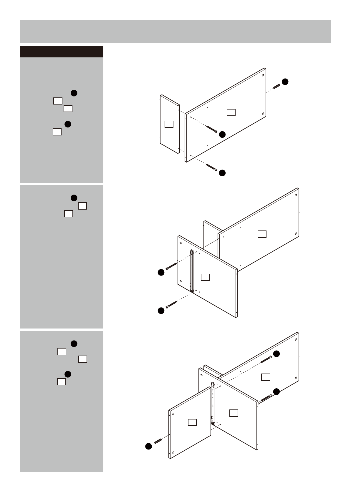
Assembly Instructions
Step 2
Attaching the middle
shelf panel
a:
Use Screws to fix
Left shelf onto the
Middle panel .
Insert Dowels into the
Left shelf .
C
7
4
H
7
b:
Use Screws to fix
Middle right panel onto
the Left shelf .
C
3
7
a:
H
7
4
C
C
b:
7
c:
Use Screws to fix
Right shelf onto the
Middle right panel .
Insert Dowels into the
Right shelf .
C
8
3
H
8
C
3
C
c:
C
7
C
3
8
Continued on next page.
H
6
Page 8
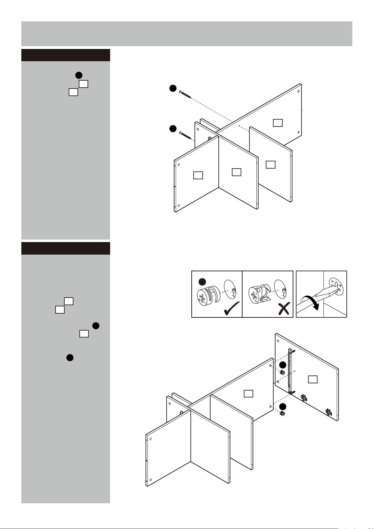
Assembly Instructions
Step 2 - continued
d:
Use Screws to fix
Middle left panel onto
the Left shelf .
C
9
7
Step 3
d:
C
C
8
3
7
9
Attaching the left and
right panel
a:
Carefully locate the
Right panel onto the
Left shelf .
Insert 2 Locking nuts
into the Left shelf .
1
7
F
7
Use a screwdriver to turn
Locking nuts clockwise
F
to lock.
a:
F
F
1
7
F
Continued on next page.
7
Page 9
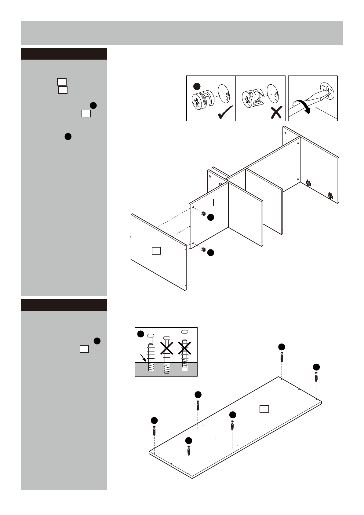
Assembly Instructions
Step 3 - continued
b:
Carefully locate the
Left panel onto the
Right shelf .
2
8
b:
F
Insert 2 Locking nuts
into the Right shelf .
F
8
Use a screwdriver to turn
Locking nuts clockwise
F
to lock.
8
F
2
F
Step 4
Attaching top panel
a:
Screw Locking pins
into the Top panel .
Note:
Insert locking pins
as far as shown.
Do not over tighten.
Continued on next page.
5
a:
E
E
E
E
E
5
E
E
E
8
Page 10
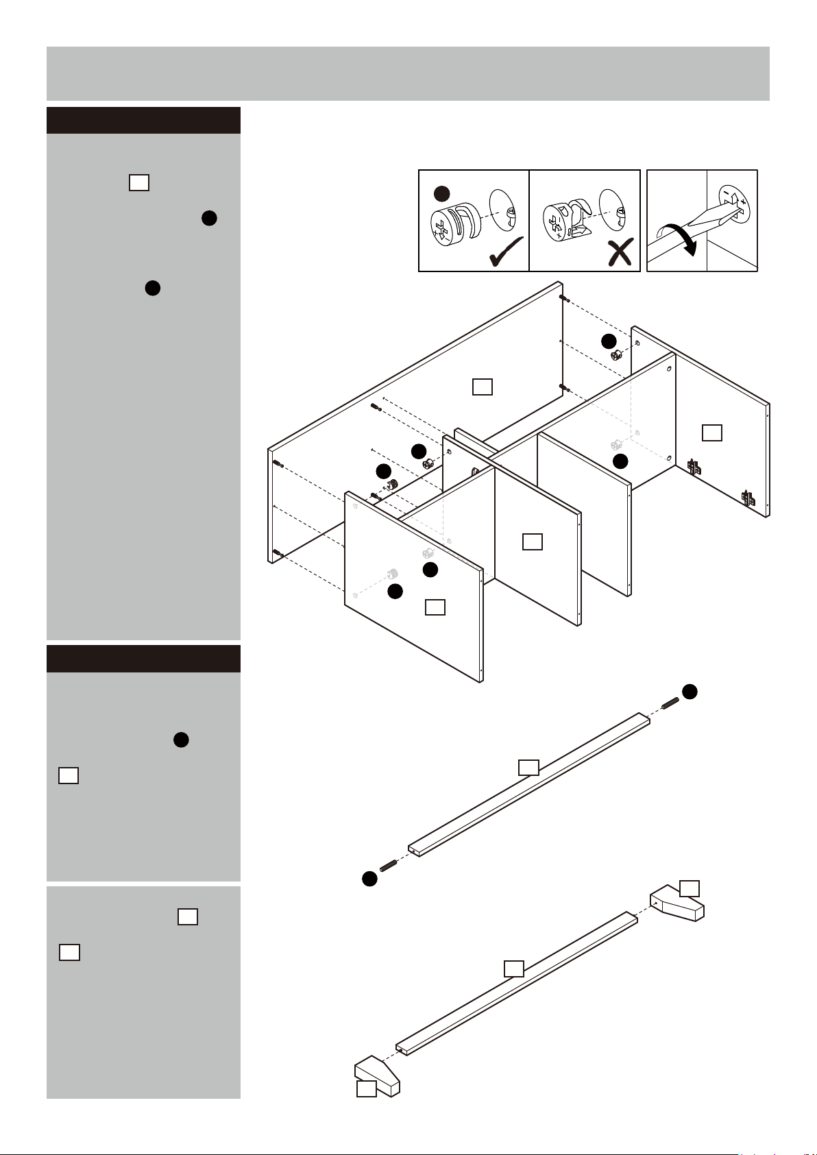
Assembly Instructions
Step 4 - continued
b:
Carefully locate the
Top panel onto the unit.
Insert 6 Locking nuts
into the unit.
Use a screwdriver to turn
Locking nuts clockwise
to lock.
5
F
F
b:
F
F
5
1
F
F
3
F
Step 5
Attaching bottom panel
a:
Insert Dowels into
the Front bottom panel
19
.
b:
Position Legs onto
the Front bottom panel
19
.
H
20
a:
b:
F
F
2
H
19
X 2
H
19
20
Continued on next page.
9
X 2
20
Page 11
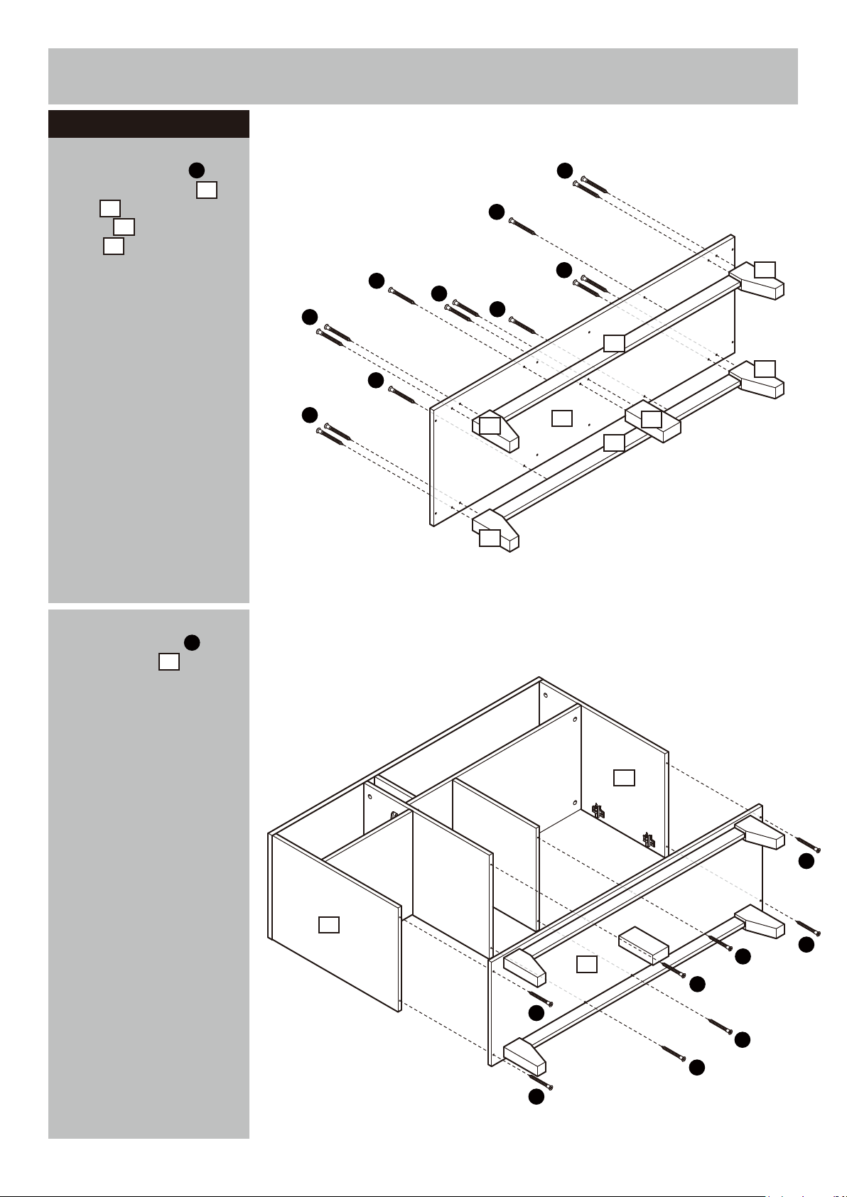
Assembly Instructions
Step 5 - continued
c:
Use 14 Screws to fix
Front bottom panel ,
Legs and Bottom
support onto the Bottom
panel .
20
21
6
C
19
c:
C
C
C
C
C
C
C
C
20
20
C
19
6
21
19
20
20
d:
Use 8 Screws to fix
Bottom panel onto the
C
6
unit.
d:
1
C
2
6
C
C
C
C
C
C
C
10
Page 12
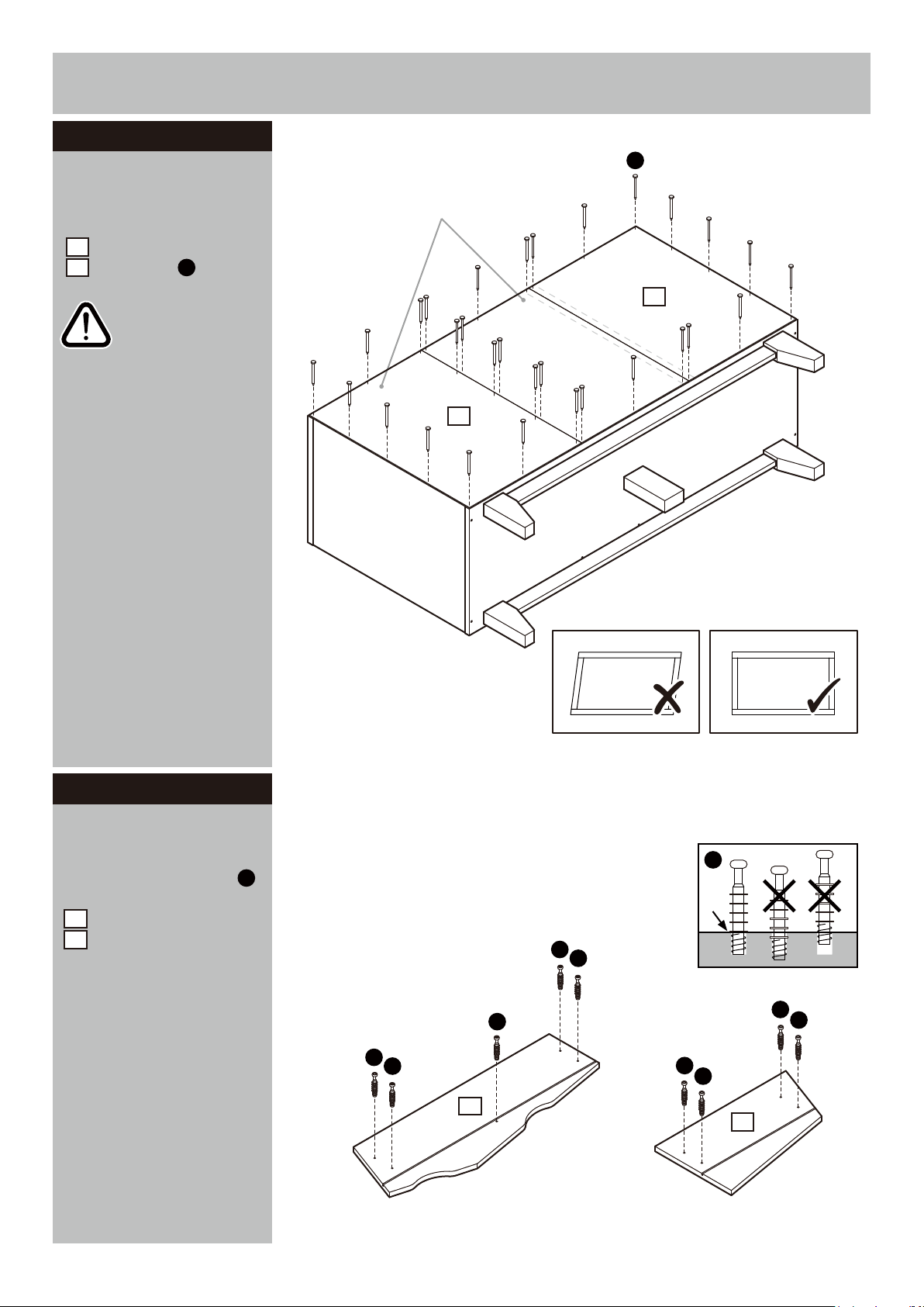
Assembly Instructions
Step 6
Fixing back panels
Unfinished back surface
Attach Small back panel
26
and Large back panel
25
using nails .
N
N
Important:
The unit MUST
be ‘square’ when
back is attached.
25
26
Step 7
Drawer assembly
a:
Screw Locking pins
into the Large drawer front
10
and Small drawer front
11
.
Note:
Insert locking pins
as far as shown.
Do not over tighten.
Continued on next page.
E
a:
E
E
E
E
E
E
E
10
E
E
11
E
11
Page 13
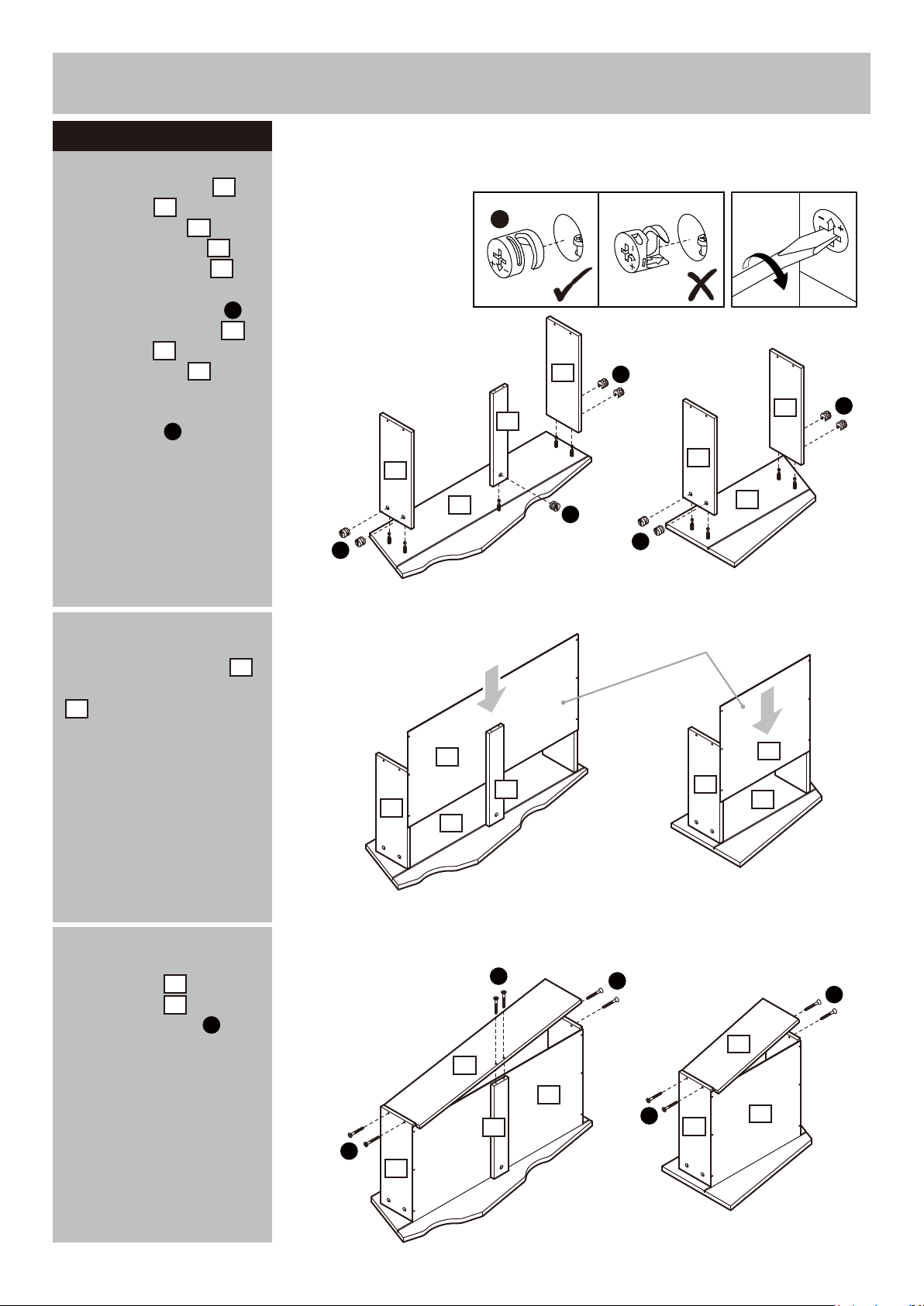
Assembly Instructions
Step 7 - continued
b:
Fix Drawer right ,
Drawer left and
Drawer support on to
Large drawer front and
Small drawer front .
Insert 9 Locking nuts
into the Drawer right ,
Drawer left and
Drawer support .
16
16
17
18
10
11
G
17
18
Use a screwdriver to turn
Locking nuts clockwise
G
to lock.
b:
G
16
18
17
10
G
G
G
16
17
11
G
G
c:
Carefully slide the
Large drawer bottom
14
and Small drawer bottom
into the grooves.
15
d:
Position the Large
drawer back and Small
drawer back onto the
unit using Screws .
12
13
D
c:
d:
17
14
10
12
Unfinished back surface
15
18
D
D
17
11
D
13
Continued on next page.
14
D
18
D
17
17
15
12
Page 14
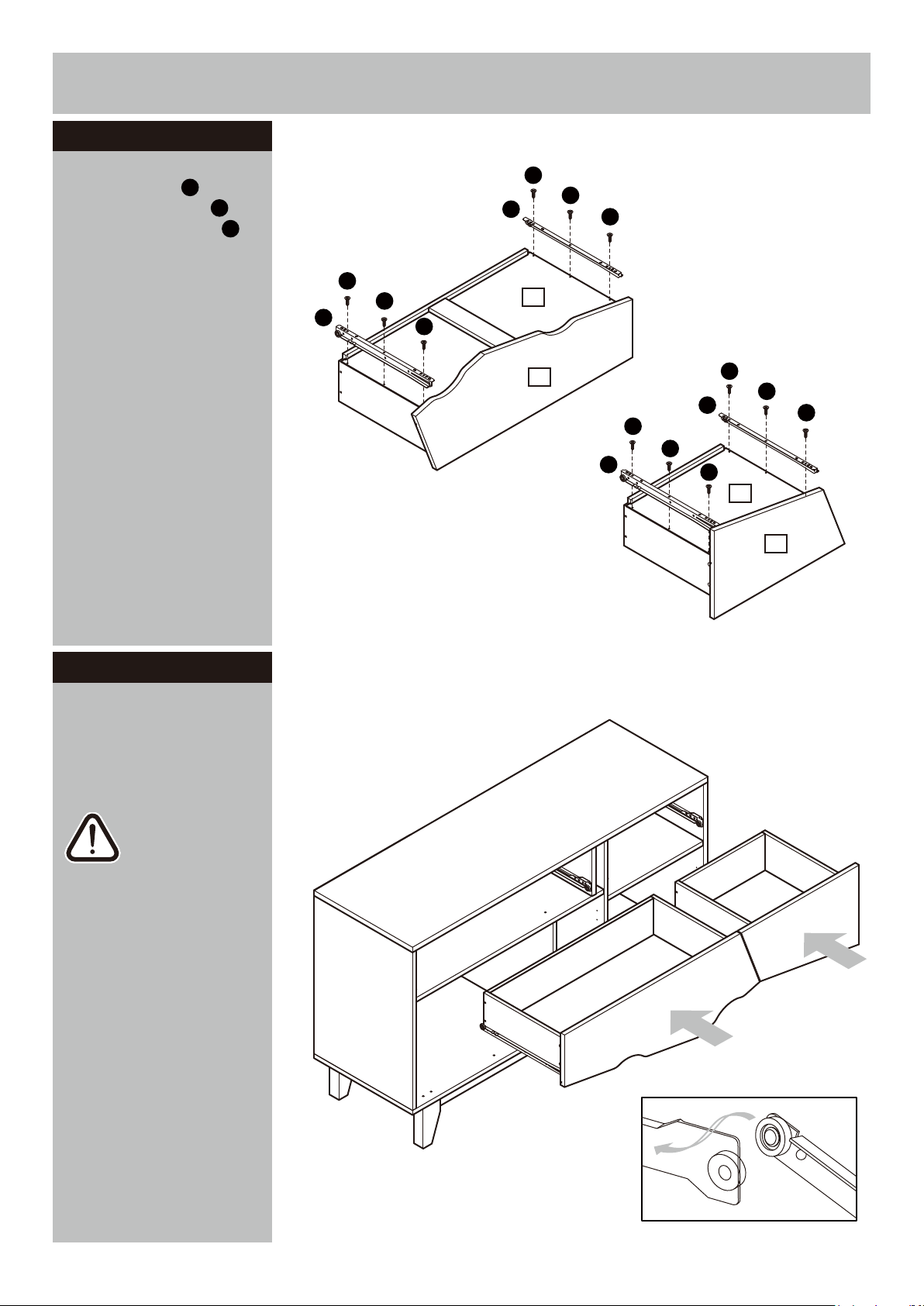
Assembly Instructions
Step 7 - continued
e:
Use Screws to fix the
Left inside runners and
Right inside runners
A
M
K
onto the unit.
e:
A
14
10
A
A
A
M
A
A
K
A
A
A
15
11
M
A
A
K
A
Step 8
Inserting drawers
With help, carefully stand
unit upright.
Warning:
The unit is heavy.
Lift with care.
Slide the assembled
drawers fully onto runners.
13
Page 15
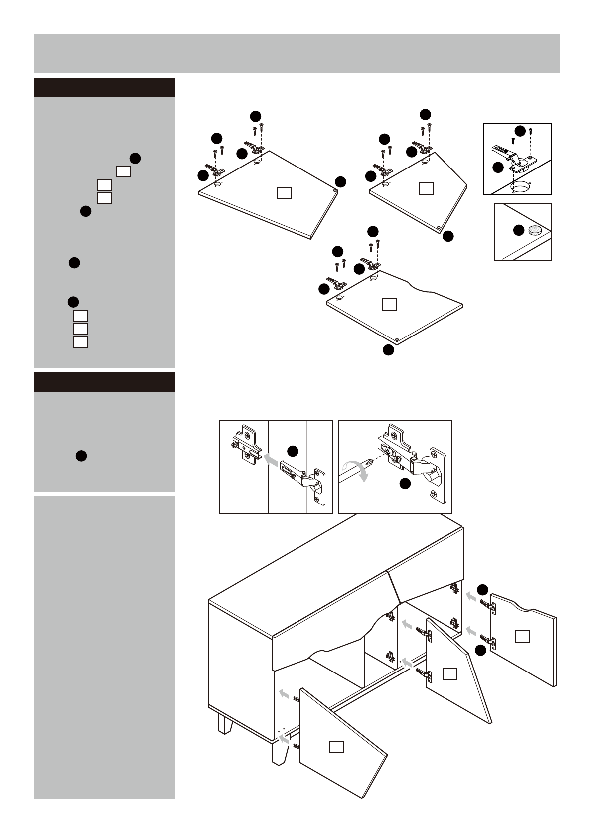
Assembly Instructions
Step 9
Attaching hinges to
doors
Fix 6 Door hinges to
Left door panel , Middle
door panel and Right
door panel using
Screws .
23
24
B
I
22
Tear off the protective
backing from the Door
Pads .
O
Carefully stick the Door
O
pads onto the Left door
panel , Middle door
panel and Right door
panel .
22
23
24
Step 10
B
B
I
I
22
O
B
I
B
I
B
I
24
O
B
B
I
I
23
O
O
Hanging doors
a:
With help, slot Door
hinges onto ‘hinge
I
plates’.
b:
Tighten screw shown
to lock hinges in position.
Repeat
a
and b for
opposite door.
Hinge adjustment
See ‘
’
in step 11 if the doors
need adjusting.
a:
I
I
b:
I
24
I
23
22
14
Page 16
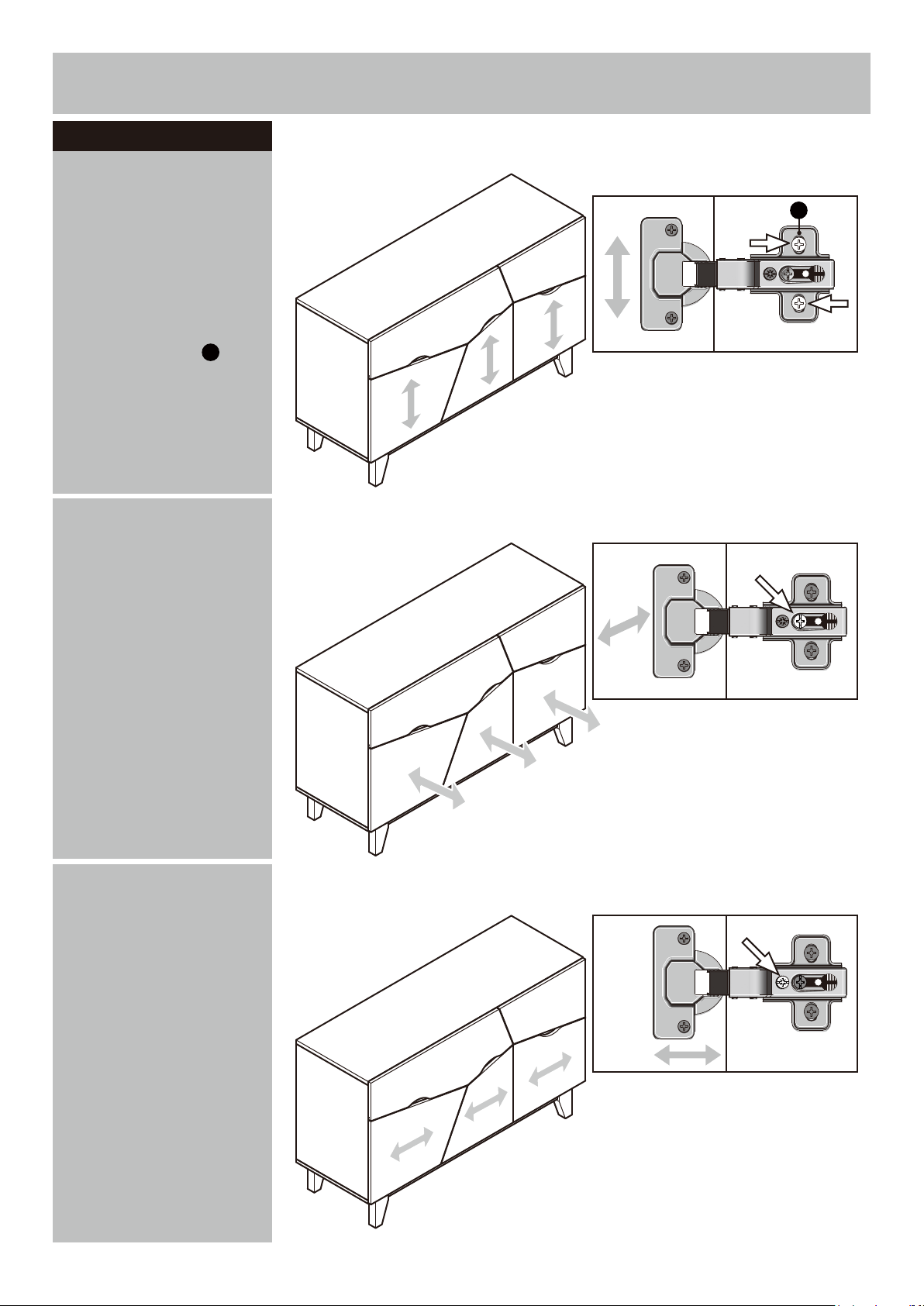
Assembly Instructions
Step 11
Hinge adjustment
a:
To move doors up or
down: loosen screws
shown and move doors to
suit.
a:
B
Once doors are aligned,
re-tighten Screws .
b:
To move doors in or
out: loosen screw shown
and move doors to suit.
Re-tighten screws.
B
Door
b:
Door
c:
To move doors left or
right: loosen screw shown
and move doors to suit.
Re-tighten screws.
15
c:
Door
Page 17
Assembly Instructions
Step 12
Finishing the unit
It would be useful
Note:
to ask someone to help
you at this stage.
With help, place the unit
in the intended position.
Assembly is complete.
If you need help or have damaged or missing parts, call the Customer Helpline:
Argos = 0345 6400800
16
 Loading...