

Page 1
MADE IN
BRITAIN
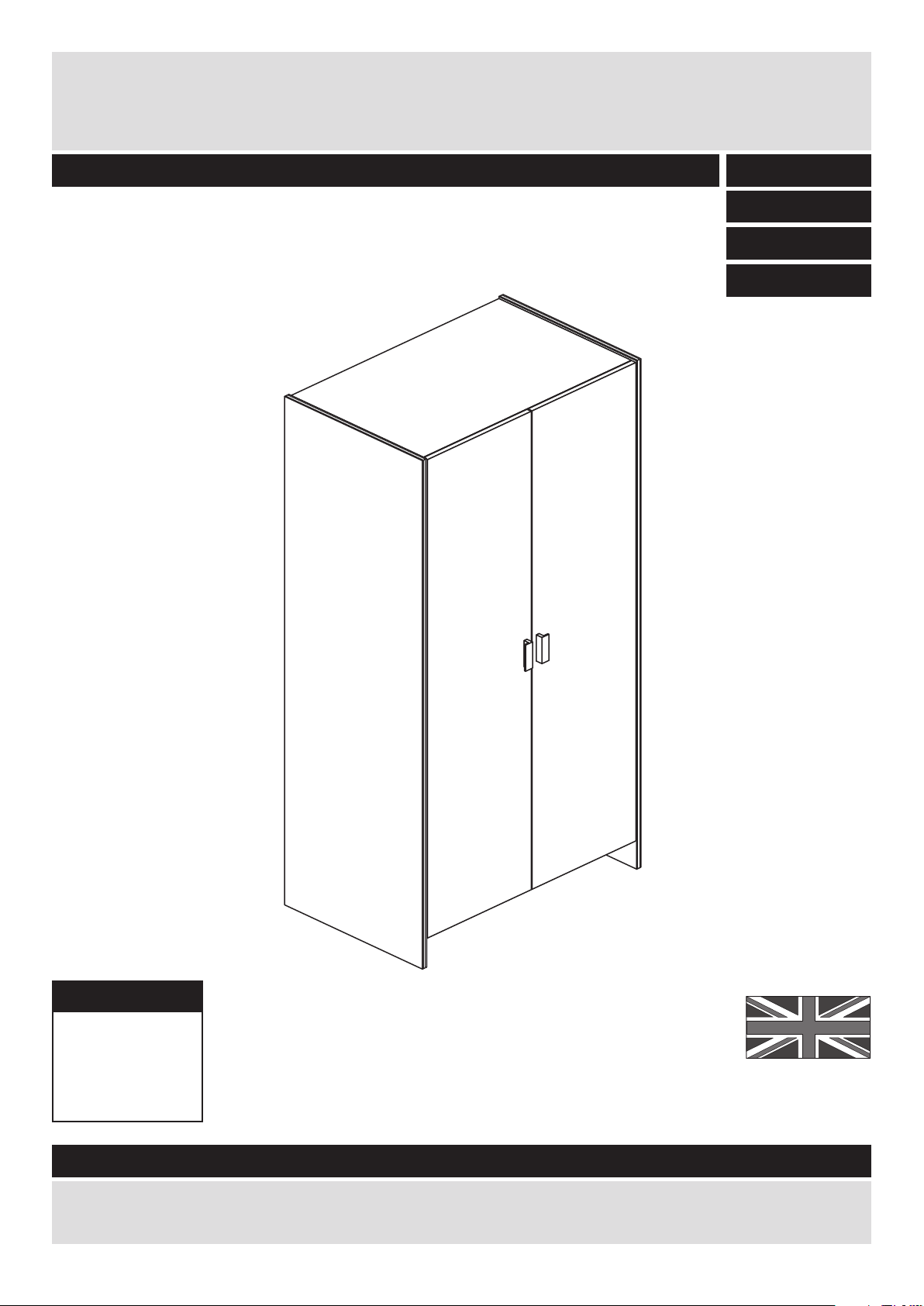
Dimensions
Width - 78cm
Depth - 49cm
Height - 181cm
Capella - 2 Door Robe
Assembly Instructions - Please keep for future reference
If you need help or have damaged or missing parts, call the Customer Helpline: 03456 400800
Issue 4 - 15/01/15
Important - Please read these instructions fully before starting assembly
267/9965
259/9760
228/5964
615/6154
257/7548
Page 2
Safety and Care Advice
Important - Please read these instructions fully before starting assembly
• Warning: This unit weighs
approximately 44kgs.
Please lift with care.
• Check you have all the
components and tools listed on
pages 2 and 3.
• Remove all fittings from the
plastic bags and separate them
into their groups.
• Keep children and animals
away from the work area, small
parts could choke if swallowed.
• Parts of the assembly will be
easier with 2 people.
• Make sure you have enough
space to layout the parts before
starting.
• Do not stand or put weight on
the product, this could cause
damage.
• Assemble the item as close to
its final position (in the same
room) as possible.
• Assemble on a soft level
surface to avoid damaging the
unit or your floor (use opened
out unit carton).
1
Care and maintenance
• Only clean using a damp cloth
and mild detergent, do no use
bleach or abrasive cleaners.
• From time to time check that
there are no loose screws on
this unit.
• This product should not be
discarded with household
waste. Take to your local
authority waste disposal centre.
Note: If required the next page
can be cut out and used as
reference throughout the
assembly. Keep this page with
these instructions for future
reference.
• We do not
recommend the
use of power
drill/drivers for
inserting screws,
as this could damage the unit.
Only use hand screwdrivers.
• Safety note: It is
recommended that this unit is
secured to a wall using the
overbalance protector kit
supplied or, an alternative fixing
method of your choice.
• Dispose of all packaging
carefully and responsibly.
Page 3
Components - Panels
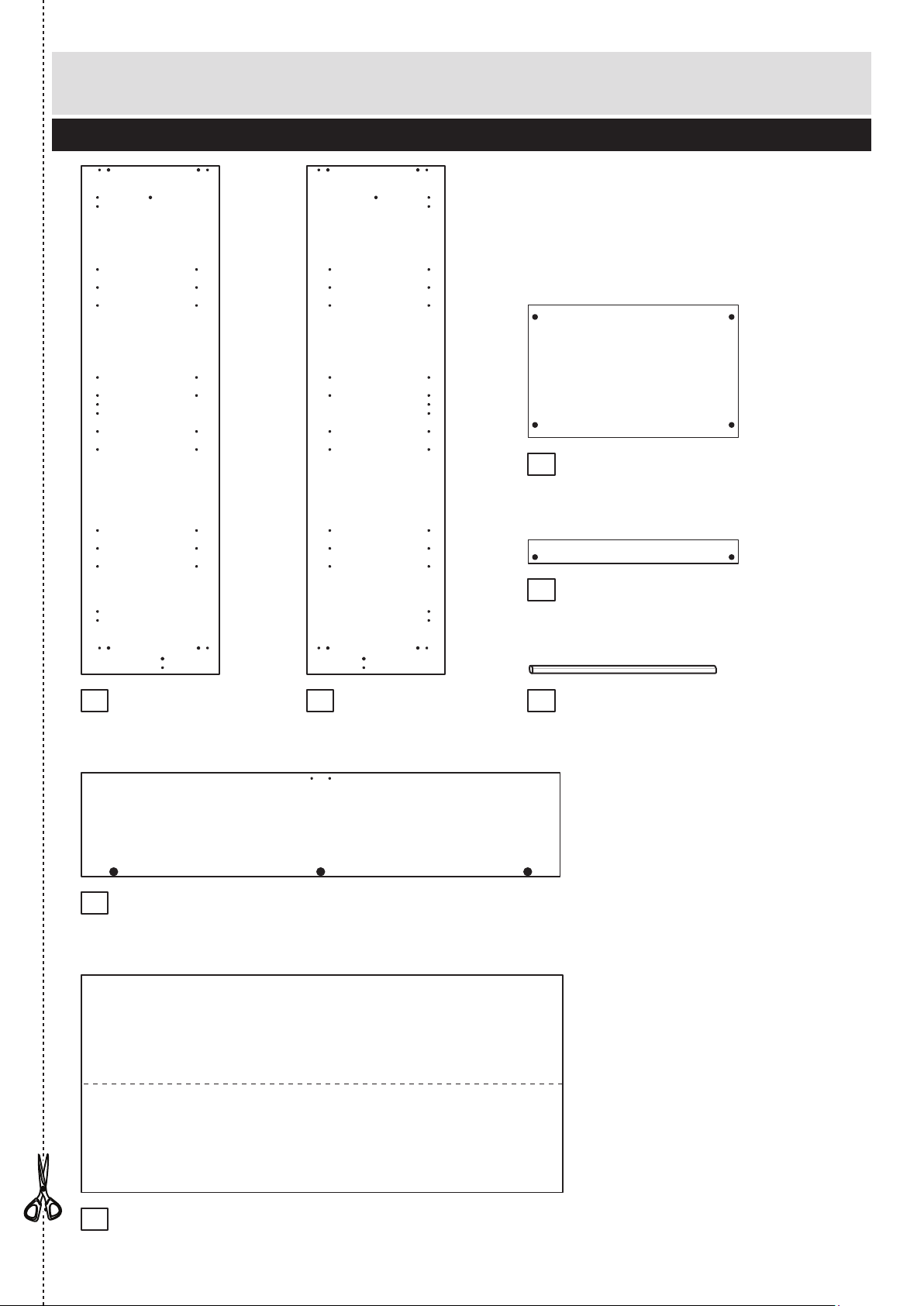
Please check you have all the panels listed below
2
1
If you have damaged or missing components, call the
Customer Helpline: 03456 400800 quoting the reference
numbers below
2
Top/Base (D1015A)
(747 x 471mm) x 2
Door (D1017A)
(1701 x 369mm) x 2
Back (X829A)
(1711 x 773mm)
Plinth (D1016A)
(747 x 85mm)
Left Side (D1013A)
(1808 x 490mm)
6
7
Right Side (D1014A)
(1808 x 490mm)
3
4
Hanging Rail (FHR737)
(737mm long)
5
Page 4
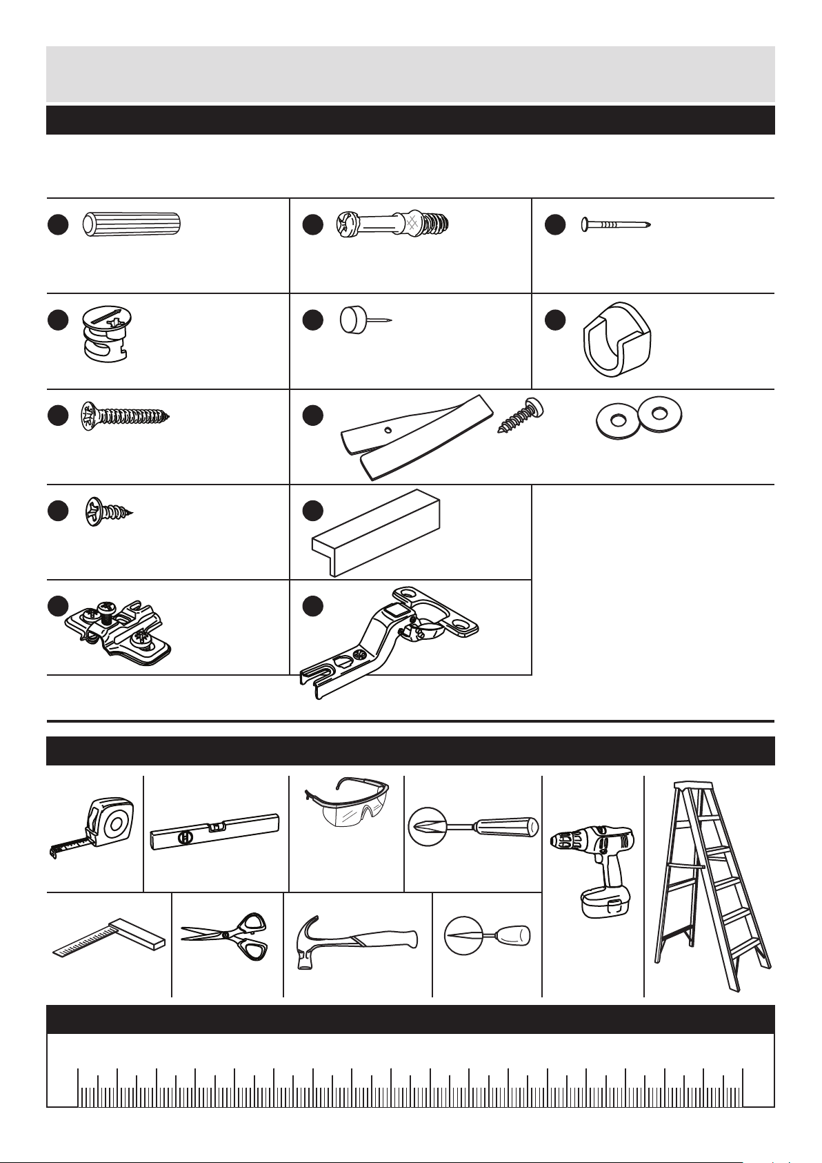
Please check you have all the fittings listed below
3
Components - Fittings
If you have damaged or missing components, call the
Customer Helpline: 03456 400800 quoting the reference
numbers below
Note: The quantities below are the correct amount to complete the assembly. In some cases
more fittings may be supplied than are required.
A
Wooden dowel (F22) x 10
B
Metal dowel (F901) x 10
C
D E
Large locking
nut (F900) x 10
F
G H
I
Nail (F51) x 34
J
K
Rail holder
(F1014) x 2
Handle (F930) x 2
25mm Screw (F50) x 4
L
Hinge (F522) x 6
Hinge plate
(F523) x 6
mm 10 20 30 40 50 60 70 80 90 100 110 120 130 140 150 160 170
Tools required
Rule
Scissors
Spirit
level
Hammer Bradawl
Eye protection
(when using a
hammer or drill)
Cross-head
screwdriver
mm 10 20 30 40 50 60 70 80 90 100 110 120 130 140 150 160 170
Step
ladder
Ruler - Use this ruler to help correctly identify the screws
Electric drill
(only use
when drilling
into walls)
Square
mm
10
20
30
40
50
60
70
80
90
100
mm
10
20
30
40
50
60
70
80
90
100
13mm Screw (F63) x 12
Plastic Nail (F91) x 4
Strap Screw Washer x 2
Overbalance protector kit (F269) x 1
Page 5
Profiled
front edge
Profiled
front edge
Assembly Instructions
4
If you have damaged or missing components, call the
Customer Helpline: 08456 400800 quoting the reference
numbers below
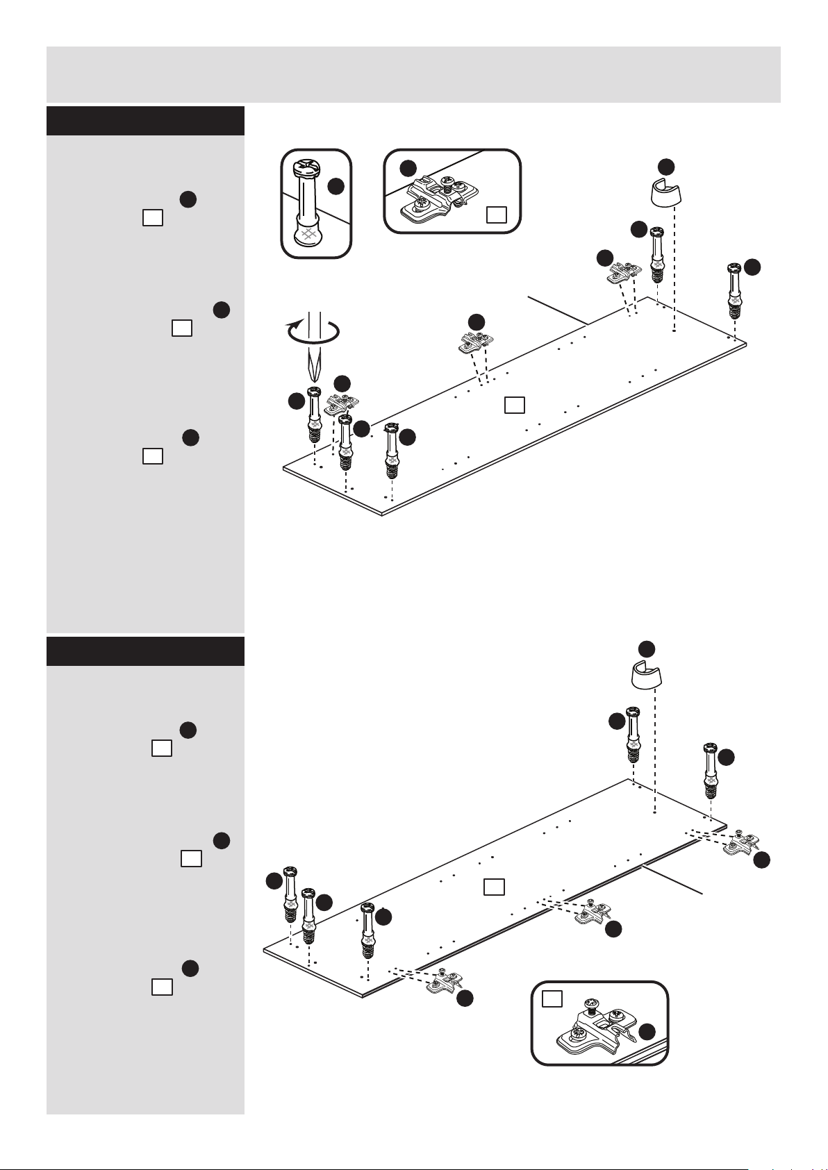
Step 1
Step 2
1
K
K
K
K
Prepare the left side
Fit 3 hinge plates onto
the left side , making
sure that the slot is
facing towards the
finished front edge.
Screw 5 metal dowels
into the left side .
Note: Tighten the metal
dowels up fully against
the panels.
Push a rail holder into
the left side . Make
sure that it is fitted
straight, in line with the
panel edges.
B
B
B
B
B
B
F
B
B
K
1
1
B
1
F
1
Prepare the right side
Fit 3 hinge plates onto
the right side , making
sure that the slot is
facing towards the
finished front edge.
Screw 5 metal dowels
into the right side .
Note: Tighten the metal
dowels up fully against
the panels.
Push a rail holder into
the right side . Make
sure that it is fitted
straight, in line with the
panel edges.
K
2
B
2
F
2
2
K
K
K
K
B
B
B
B
B
F
2
Page 6
Profiled
front edge
Finished
front edge
Finished
front edge
A
Assembly Instructions
5
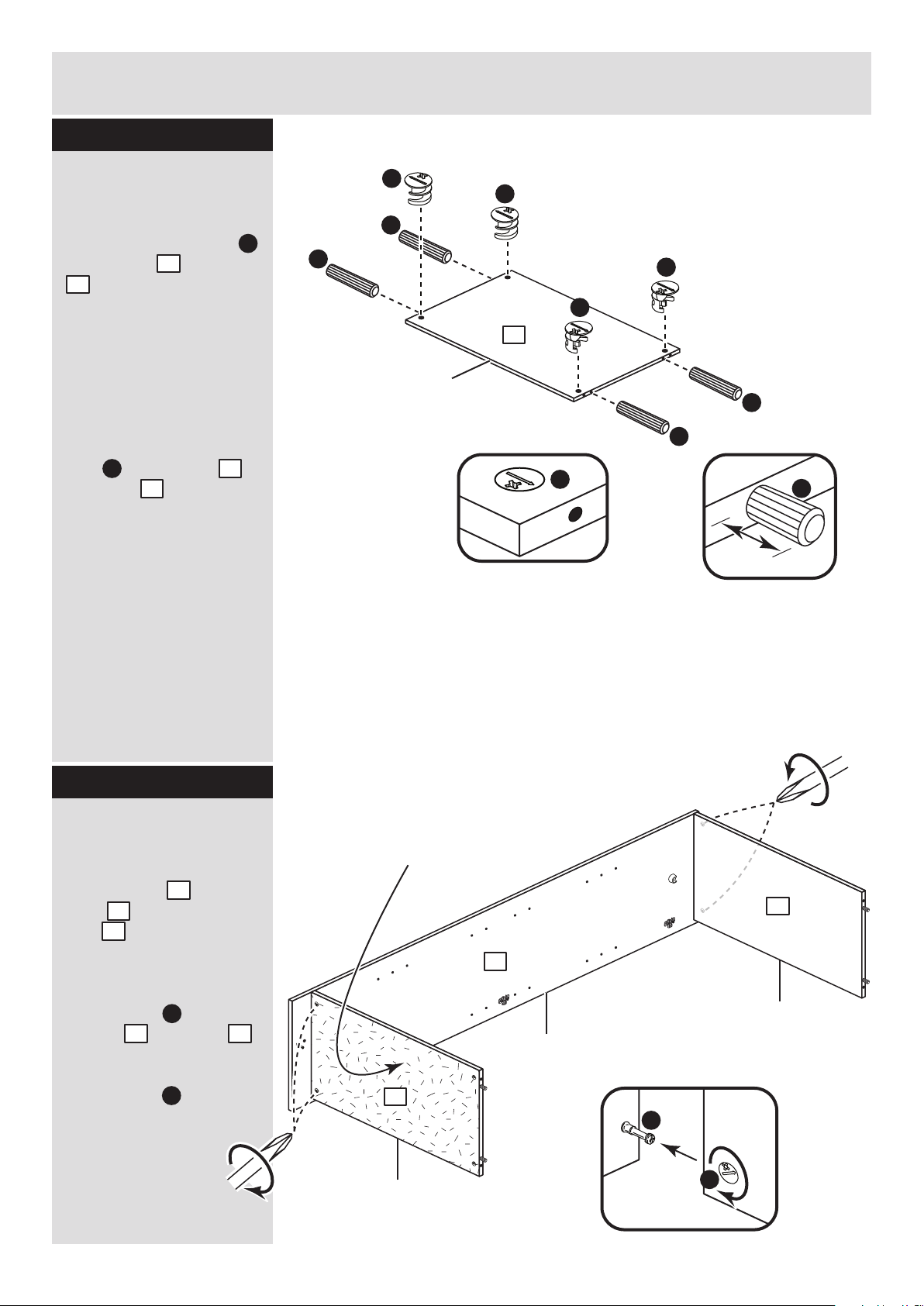
Step 3
Step 4
Prepare the top and
base
Tap 4 wooden dowels
into the top and base
. as shown.
Note: Wooden dowels
must not stick out from
the edge by more than
10mm or they may
damage other panels.
Insert 4 large locking
nuts into the top
and base as shown.
Note: The arrow on the
locking nut must point
towards the hole in the
edge of the panel.
D
D
D
D
D
A
A
A
10mm
A
A
3
3
3
3
D
Finished
front edge
3
Fit the top and base
to the right side
Push the top and
base onto the right
side as shown.
Use a screwdriver to
tighten the 4 large
locking nuts fitted to
the top and base .
Note: Turn the large
locking nuts as far as
they will go - more than
1/2 a turn.
3
3
2
D
D
3 3
D
B
3
3
2
x 2
Important: If one of the top/base
panels has a plain chipboard surface
this must be used as the base.
Important: If one of the top/base
panels has a plain chipboard surface
this must be used as the base.
Page 7
Profiled
front edge
A
A
Assembly Instructions
6
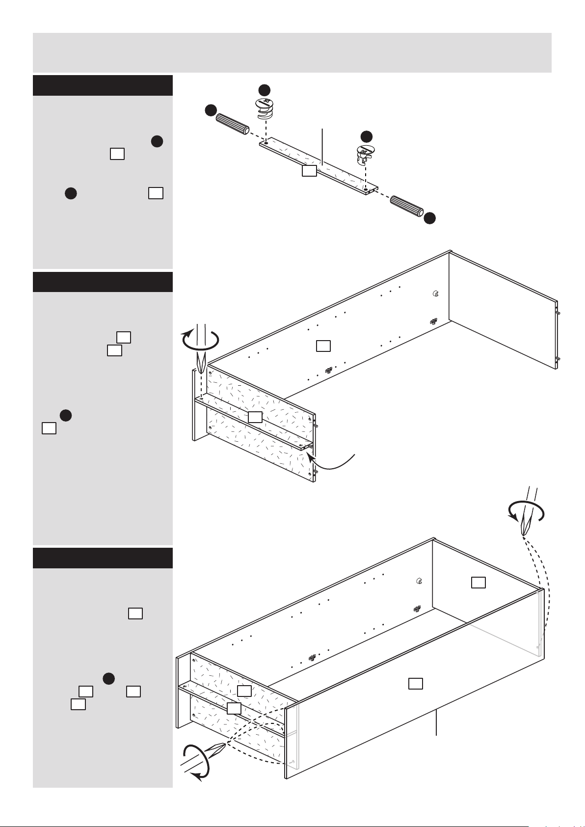
Step 5
D
D
A
Prepare the plinth
Tap 2 wooden dowels
into the plinth .
Insert 2 large locking
nuts into the plinth
4
4
4
D
.
Note: Support the plinth
until the left side has been
fitted in the next step.
Step 6
Fit the plinth
Push the plinth onto
the right side as
shown.
Use a screwdriver to
tighten the large locking
nut fitted to the plinth
. .
Step 7
Fit the left side
Push the left side
onto the assembly.
Use a screwdriver to
tighten the 5 large
locking nuts fitted to
the top , base and
plinth .
4
2
4
2
D
4
4
3
3
1
1
D
3 3
4
Plain chipboard
surface
Page 8
y
Assembly Instructions
7
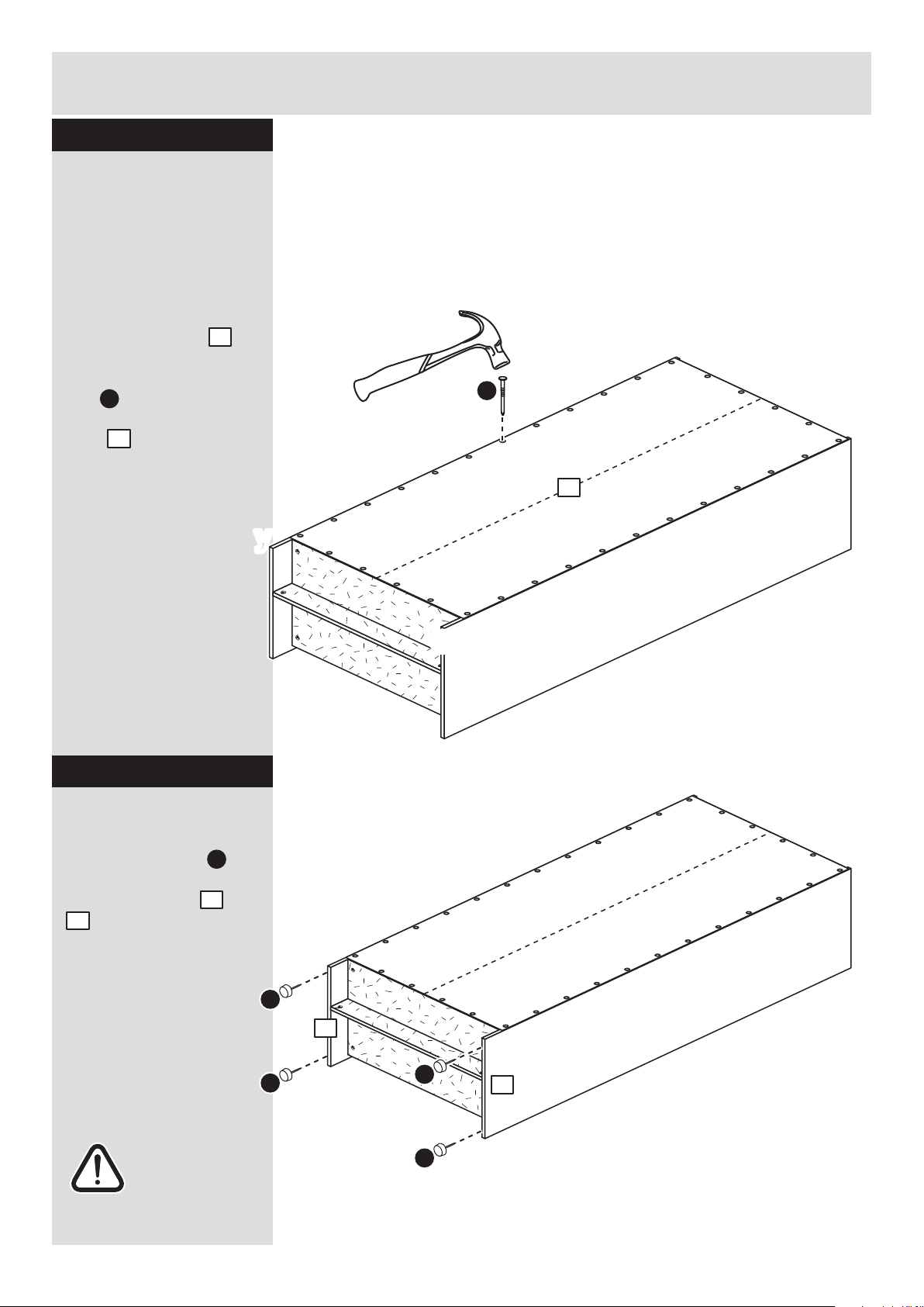
Step 8
y
x
x
b:
Fit the back
a: Square up the unit by
making sure that
measurement x to x
equals y to y.
b: Place the back
onto the unit.
Nail around the
outside edges of the
back .
Note: Nails should
be spaced about 150mm
apart.
7
C
The measurement from top corner X to bottom corner X must be
equal to the measurement from top corner Y to bottom corner Y
a:
7
y
C
7
Warning: The
unit is heavy.
Lift with care.
Step 9
Fit the 4 plastic nails
Tap 2 plastic nails
into the bottom edge of
each of the sides and
. .
Stand the unit up
for the next step.
E
1
2
E
E
E
E
1
2
Page 9
Assembly Instructions
8
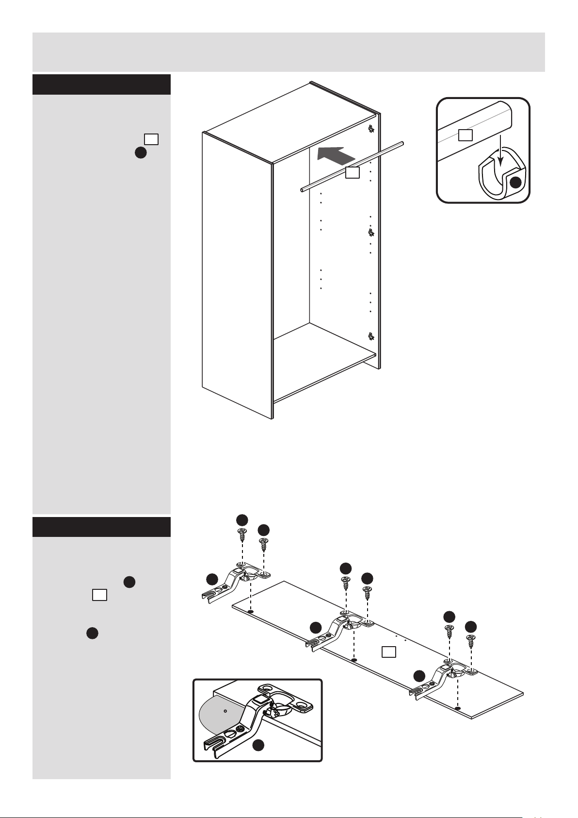
Step 10
Fit the hanging rail
Push the hanging rail
into the rail holders
fitted to the side panels.
Step 11
5
5
F
5
F
Prepare the doors
Push fit 3 hinges into
each door .
Secure each hinge with
2 screws .
Note: Before securing
with the screws, make
sure that the hinges are
positioned at 90 degrees
with the edge of the
door.
I
L
6
90
L
L
I
I
L
I
I
L
I
I
6
x 2
Page 10
Assembly Instructions
9
Step 12
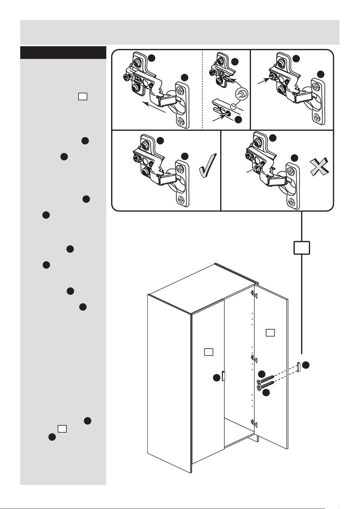
Fit doors and handles
Note: The easiest way to
attach each door is
to fit the top hinge first,
then align and fit the
other hinges.
a: Push the hinge
onto the front part of the
hinge plate .
The recess at the bottom
of screw B goes into the
slot in the hinge plate.
b: Keep the hinge
FLAT against the hinge
plate as you slide it
across as far as it will go.
Tighten screw A.
c: The hinge must be
flat against the hinge
plate prior to any
adjustment.
d: The hinge must
NOT be AT AN ANGLE
to the hinge plate
when assembled.
This would indicate that
the recess at the bottom
of screw B had not
located in the slot in the
hinge plate and the hinge
would not be secure.
Remove the hinge from
the hinge plate and then
re-assemble being
careful to follow
instructions a-c.
e: Attach a handle to
each door using 2
screws .
L
L
L
K
K
K
L
K
J
G
6
6
a: b:
c: d:
K
L
K
K
B
K
L
L
L
A
L
K
B
e:
6
6
G
G
J
J
Page 11
Assembly Instructions
10
Step 13
b:
c:
d:
a:
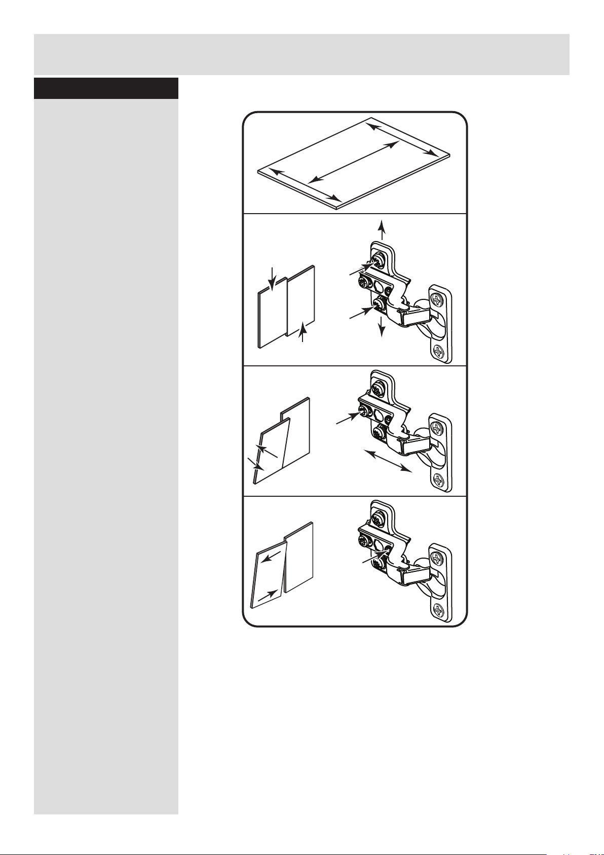
Adjust the doors if
needed
a: Before adjusting the
doors, use a spirit level
to check the base (or
top) of the unit is level,
front-to-back and
side-to-side in the 3
positions shown.
Use suitable packing
pieces (not supplied) to
make the unit level
BEFORE making any
adjustment to the hinges,
as shown.
b: Height adjustment.
Loosen screws A on
hinge plates and move
door up or down as
required.
Retighten screw A.
c: Forward and Back
adjustment.
Loosen screw B on hinge
plate and move door in
or out as required.
Retighten screw B.
d: Sideways
adjustment.
To move door ‘out’
loosen screw C.
To move door ‘in’ tighten
screw C.
A
A
B
C
Page 12
Assembly Instructions
11
If you need help or have damaged or missing parts, call the Customer Helpline: 08456 400800
and quote the reference numbers on the component pages.
Argos Ltd, 489-499 Avebury Boulevard, Central Milton Keynes, MK9 2NW
ALR2990
Step 14
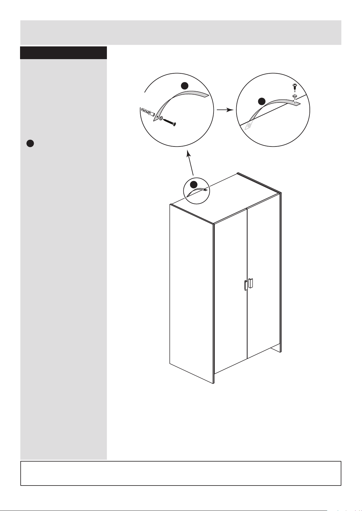
Fit the overbalance
protector kit
To prevent possible
overbalancing we
recommend that this unit
is secured to a suitable
wall by fitting of the
overbalance protector kit
. to the unit, or an
alternative fixing method
of your choice.
Wall fixings are not
supplied as they will
need to suit the wall
type.
Note: Take care when
drilling the wall that you
do not drill into any
pipes, wires etc.
If in doubt, consult an
expert.
Assembly is complete
H
H
WALL
Wall fixing
(not supplied)
Screw
(not supplied)
Washer
Strap
H
Strap
Washer
Screw
TOP OF UNIT
H
Page 13
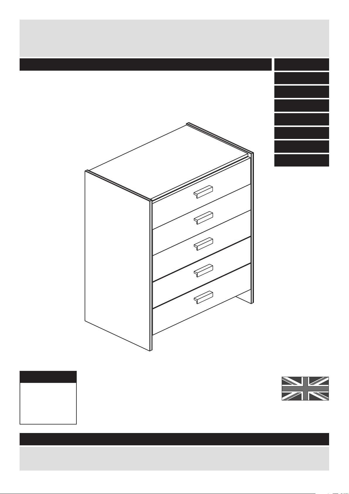
MADE IN
BRITAIN
Dimensions
Width - 63cm
Depth - 39cm
Height - 90.4cm
Capella - 5 Drawer Chest
Assembly Instructions - Please keep for future reference
If you need help or have damaged or missing parts, call the Customer Helpline: 03456 400800
Issue 8 - 15/01/15
Important - Please read these instructions fully before starting assembly
262/0804
267/5660
266/7788
254/9703
227/4061
247/7284
266/5735
274/3877
Page 14
Safety and Care Advice
Important - Please read these instructions fully before starting assembly
• Warning: This unit weighs
approximately 27kgs.
Please lift with care.
• Check you have all the
components and tools listed on
pages 2 and 3.
• Remove all fittings from the
plastic bags and separate them
into their groups.
• Keep children and animals
away from the work area, small
parts could choke if swallowed.
• Parts of the assembly will be
easier with 2 people.
• Make sure you have enough
space to layout the parts before
starting.
• Do not stand or put weight on
the product, this could cause
damage.
• Assemble the item as close to
its final position (in the same
room) as possible.
• Assemble on a soft level
surface to avoid damaging the
unit or your floor (use opened
out unit carton).
1
Care and maintenance
• Only clean using a damp cloth
and mild detergent, do no use
bleach or abrasive cleaners.
• From time to time check that
there are no loose screws on
this unit.
• This product should not be
discarded with household
waste. Take to your local
authority waste disposal centre.
Note: If required the next page
can be cut out and used as
reference throughout the
assembly. Keep this page with
these instructions for future
reference.
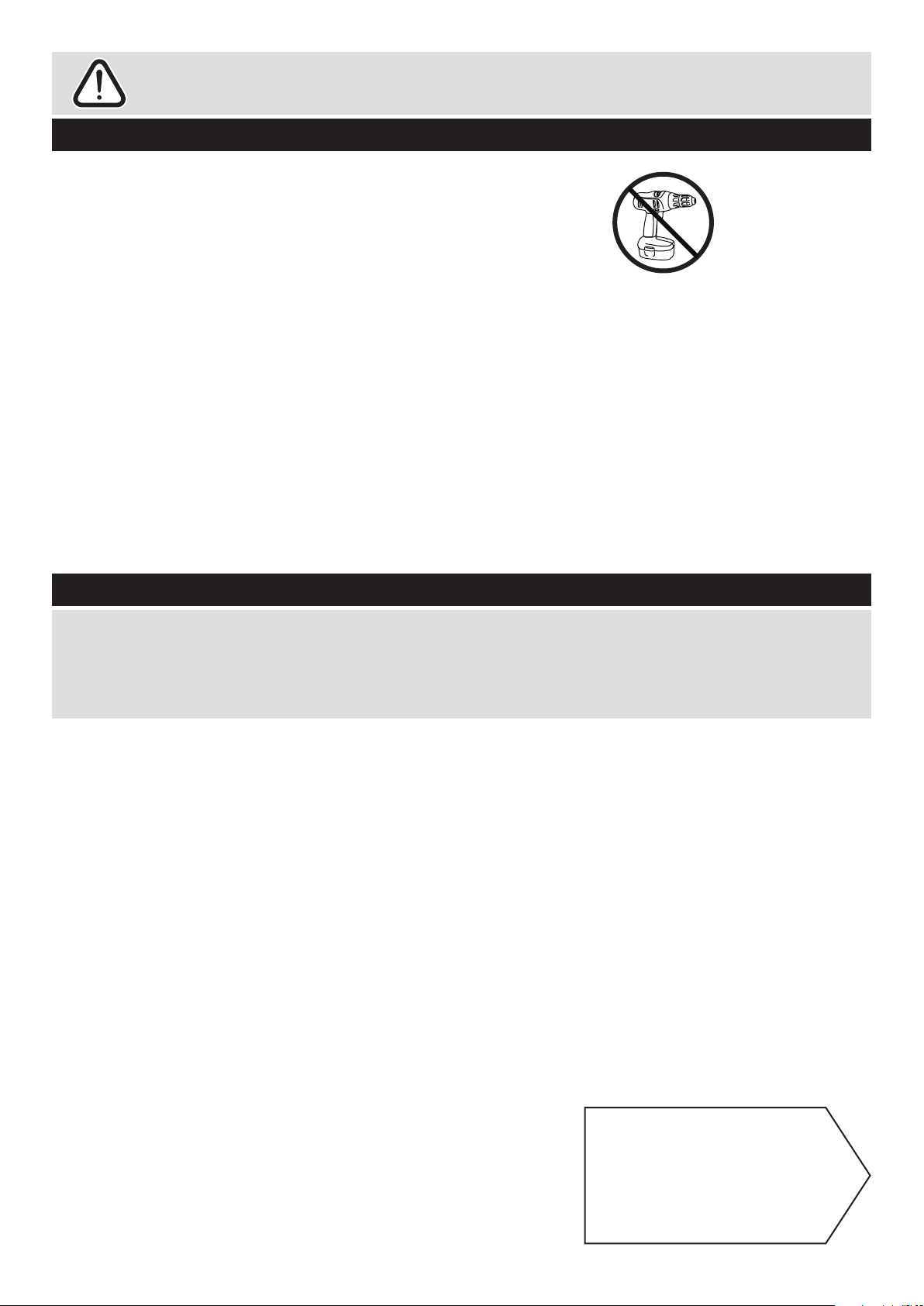
• We do not
recommend the
use of power
drill/drivers for
inserting screws,
as this could damage the unit.
Only use hand screwdrivers.
• Safety note: It is
recommended that this unit is
secured to a wall using the
overbalance protector kit
supplied or, an alternative fixing
method of your choice.
• Dispose of all packaging
carefully and responsibly.
Page 15
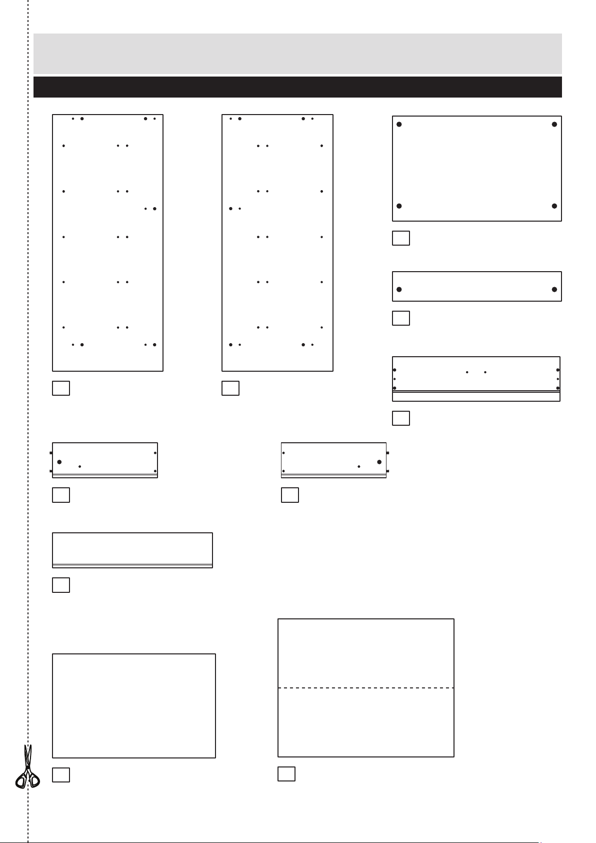
Components - Panels
Please check you have all the panels listed below
2
1
If you have damaged or missing components, call the
Customer Helpline: 03456 400800 quoting the reference
numbers below
Left Side (D1011A)
(904 x 390mm)
Top (D1008A)
(596 x 369mm)
Drawer Front (D1010A)
(592 x 157mm) x 5
Back (X828A)
(622 x 807mm)
2
Right Side (D1012A)
(904 x 390mm)
3
8
76
5
9
10
4
Rail (D1009A)
(596 x 103mm) x 3
Drawer Back (W564 - 124)
(564 x 124mm) x 5
Drawer Base (T575 - 367)
(575 x 367mm) x 5
Left Drawer Side (W370-124LH)
(370 x 124mm) x 5
Right Drawer Side (W370-124RH)
(370 x 124mm) x 5
Page 16
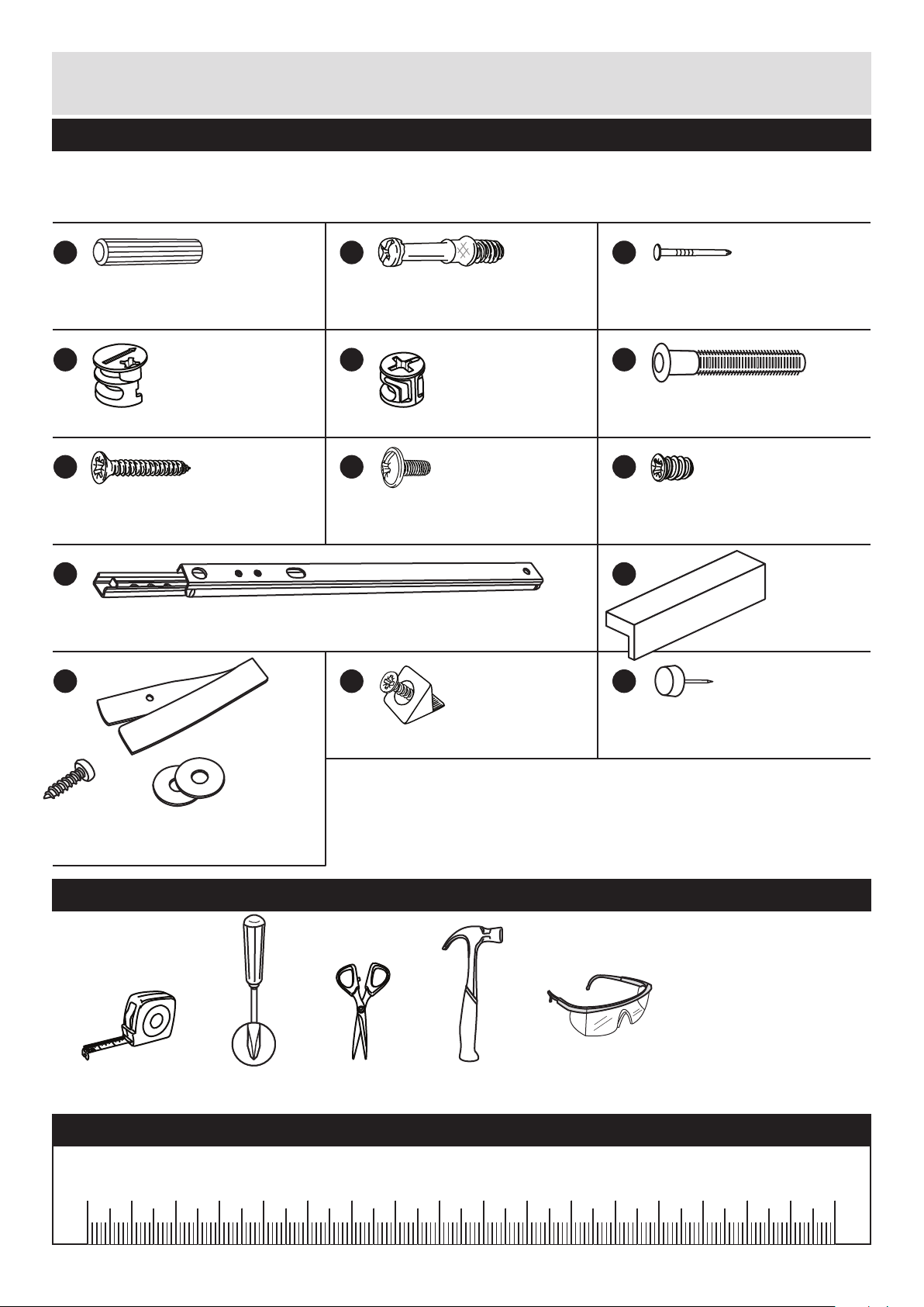
Please check you have all the fittings listed below
Tools required
3
Components - Fittings
If you have damaged or missing components, call the
Customer Helpline: 03456 400800 quoting the reference
numbers below
Note: The quantities below are the correct amount to complete the assembly. In some cases
more fittings may be supplied than are required.
A
Wooden dowel (F22) x 10
B
Metal dowel (F901) x 20
D E
Large locking
nut (F900) x 10
F
L M N
G H I
K
Rule Scissors Hammer
Eye protection
(when using a
hammer or drill)
Cross-head
screwdriver
Small locking
nut (F3) x 10
C
Nail (F51) x 16
Ruler - Use this ruler to help correctly identify the screws
mm 10 20 30 40 50 60 70 80 90 100 110 120 130 140 150 160 170
J
Drawer runner (F1004) x 10 Handle (F930) x 5
25mm Screw (F50) x 10 9mm Screw (F74) x 10 9mm Screw (F73) x 20
Knock-in Peg (F171) x 20
Plastic Nail (F91) x 4
Wedgefix (F639) x 20
Strap
Screw Washer x 2
Overbalance protector kit (F269) x 1
Page 17
Assembly Instructions
4
If you have damaged or missing components, call the
Customer Helpline: 03456 400800 quoting the reference
numbers below
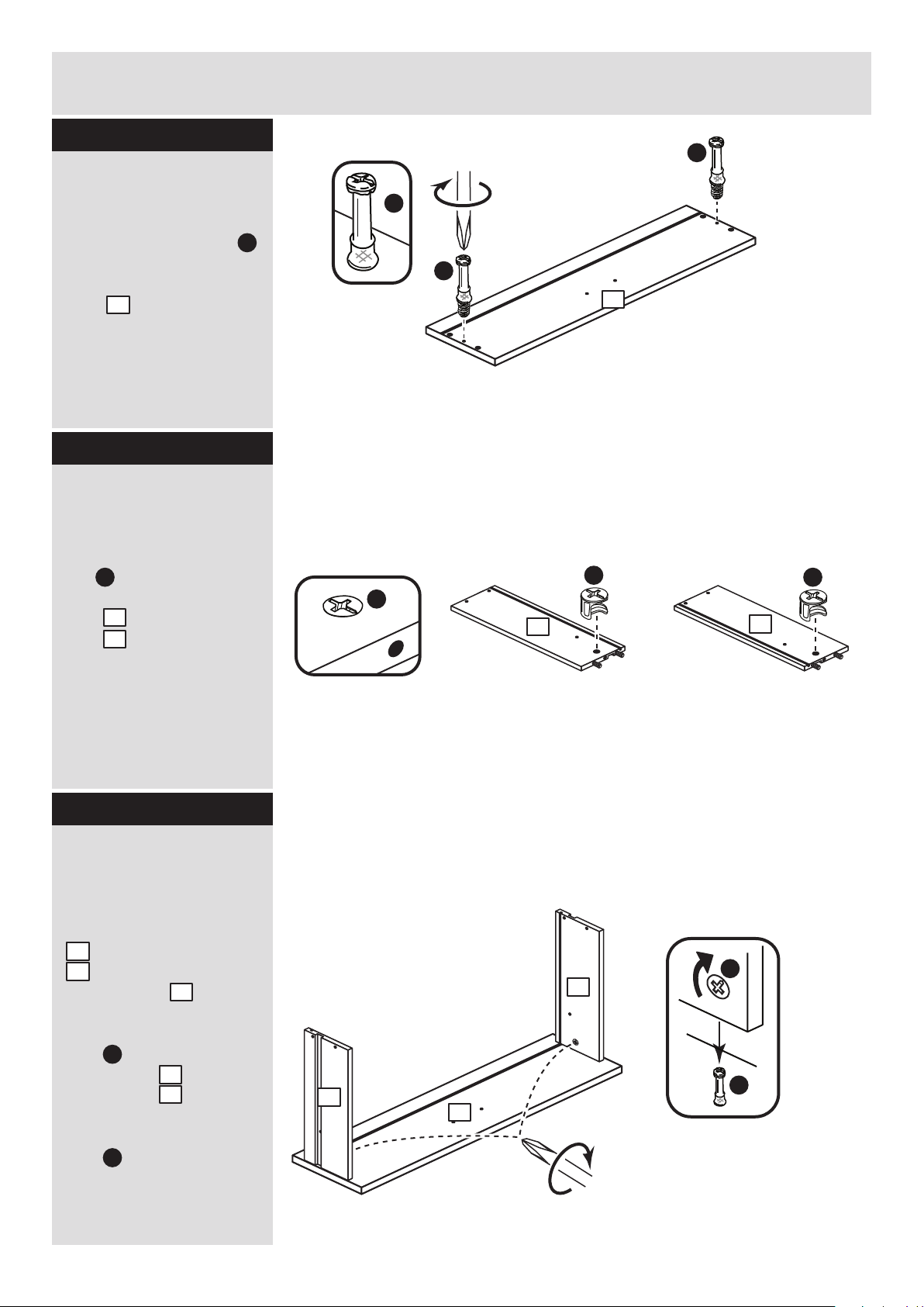
Step 1
x 5
Prepare the drawer
fronts
Screw 2 metal dowels
into the holes shown on
the back of each drawer
front .
Note: Tighten the metal
dowels up fully against
the panels.
B
5
B
B
B
B
B
5
Prepare the drawer
sides
Insert a small locking
nut into the hole
shown on the left drawer
side and right drawer
side .
Note: The arrow on the
locking nut must point
towards the hole in the
edge of the panel.
E
6
7
Step 2
x 5 x 5
E
Note: Due to the manufacturing process, the holes for the
locking nut can be on either surface of the drawer sides.
E
E
6
7
Step 3
x 5
B
E
Attach the drawer
sides to the drawer
fronts
Push the left drawer sides
. and right drawer sides
. onto the back of the
drawer fronts .
Turn the small locking
nuts on the left
drawer side and right
drawer side .
Note: Turn the locking
nuts clockwise to
secure panels - more
than 1/2 a turn.
6
7
5
E
E
6
7
Note: The locking nuts can be on either surface of the drawer sides.
Make sure that the small groove is on the inside, as shown.
7
6
5
Page 18
Assembly Instructions
5
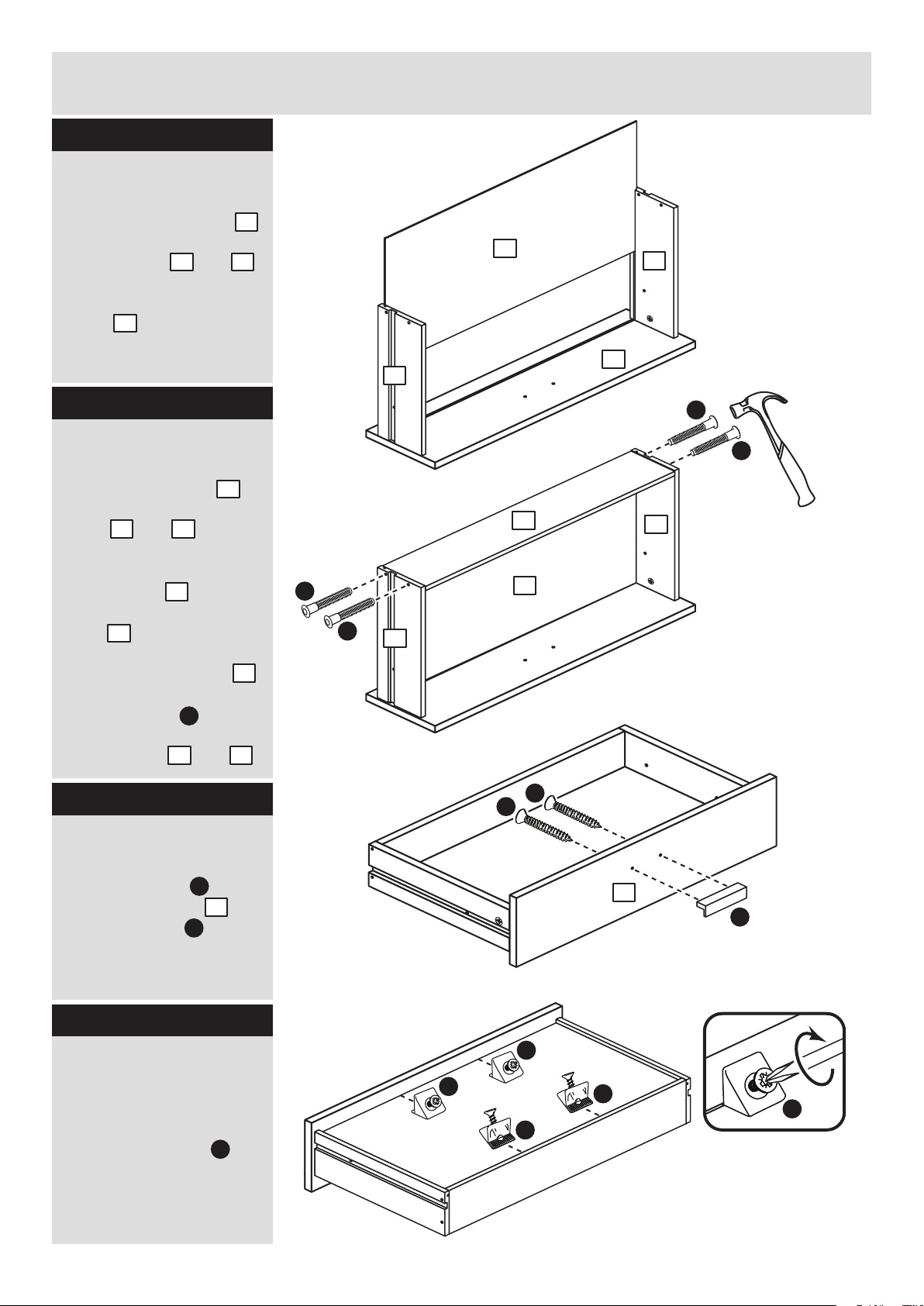
Step 4
Attach the handle
Attach a handle to
each drawer front
using 2 screws .
K
G
Step 6
5
x 5
G
G
K
5
5
F
F
Fit the drawer base
Slide the drawer base
down the grooves in the
drawer sides and
and down into the
groove in the drawer
front . .
Step 5
Fit the drawer back
Fit the drawer back .
between the drawer
sides and .
Make sure that the
drawer base fits into
the groove in the drawer
back .
Hold the drawer back
in position and tap the
knock-in pegs
through the holes in the
drawer sides and .
9
6 7
5
8
6 7
9
8
8
F
x 5
x 5
x 5
F
F
6
9
9
7
6
6 7
8
M
Fit the wedgefixes
Turn the large drawer
assemblies over and
slide 4 wedgefixes
into the front and back
grooves, as shown, and
tighten up the screws.
M
M
M
M
M
Step 7
7
Page 19
Profiled
front edge
Profiled
front edge
Assembly Instructions
6
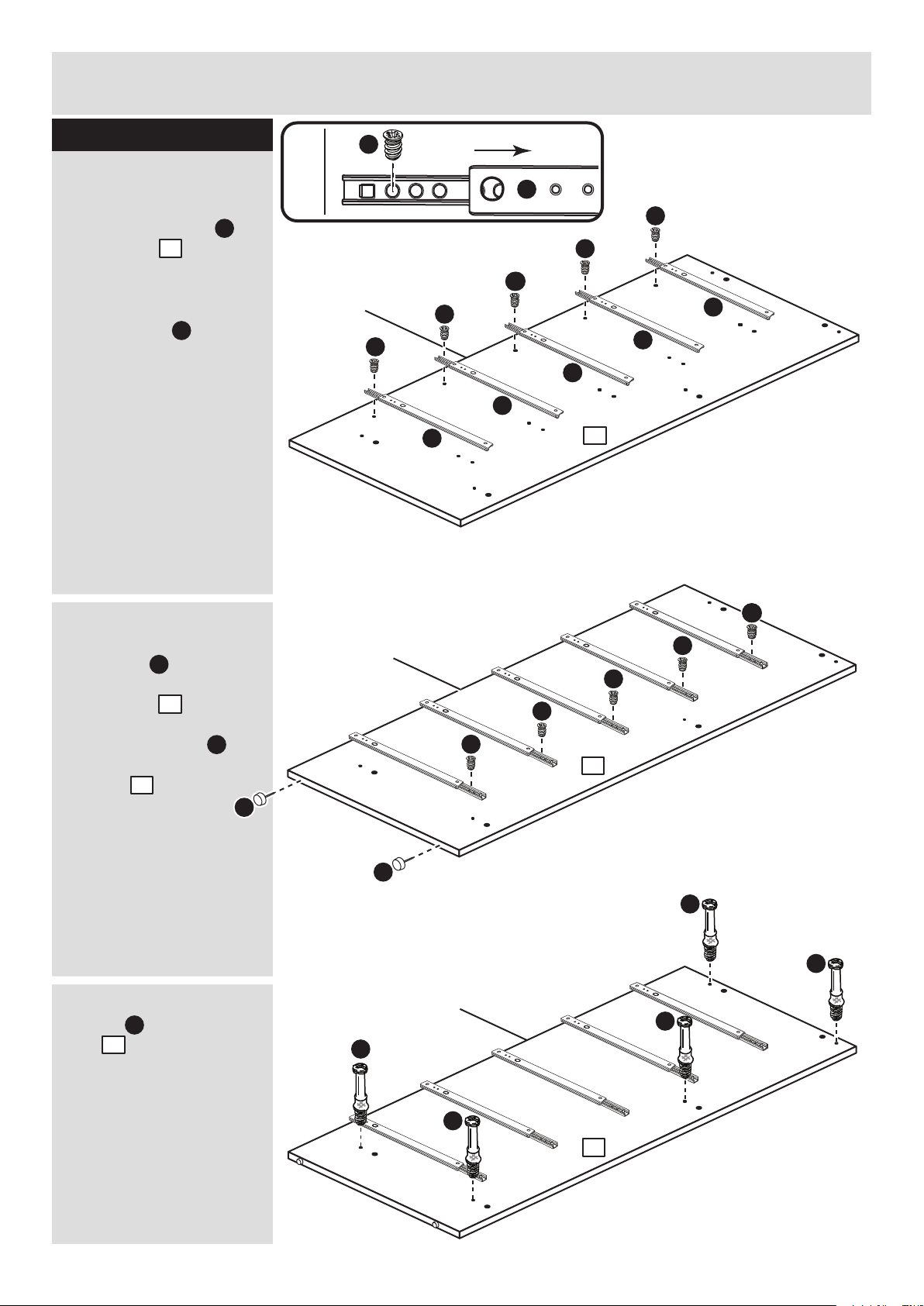
Step 8
Profiled
front edge
I
J
I
J
I
J
I
J
I
J
Profiled
front edge
I
I
I
Prepare the left side
a: Place 5 runners on
the left side . Slide
back the top of the
runner and use the 1st
hole from the front to fit
the 1st screw .
b: Slide the runner back
the other way and fit the
2nd screw into the
corresponding hole in
the left side .
Tap 2 plastic nails
into the bottom edge of
the side . .
c: Screw 5 metal
dowels into the left
side .
a:
b:
c:
1
I
B
1
1
1
I
J
I
J
I
J
I
I
II
I
1
B
B
B
B
B
N
1
N
N
1
Page 20
Assembly Instructions
7
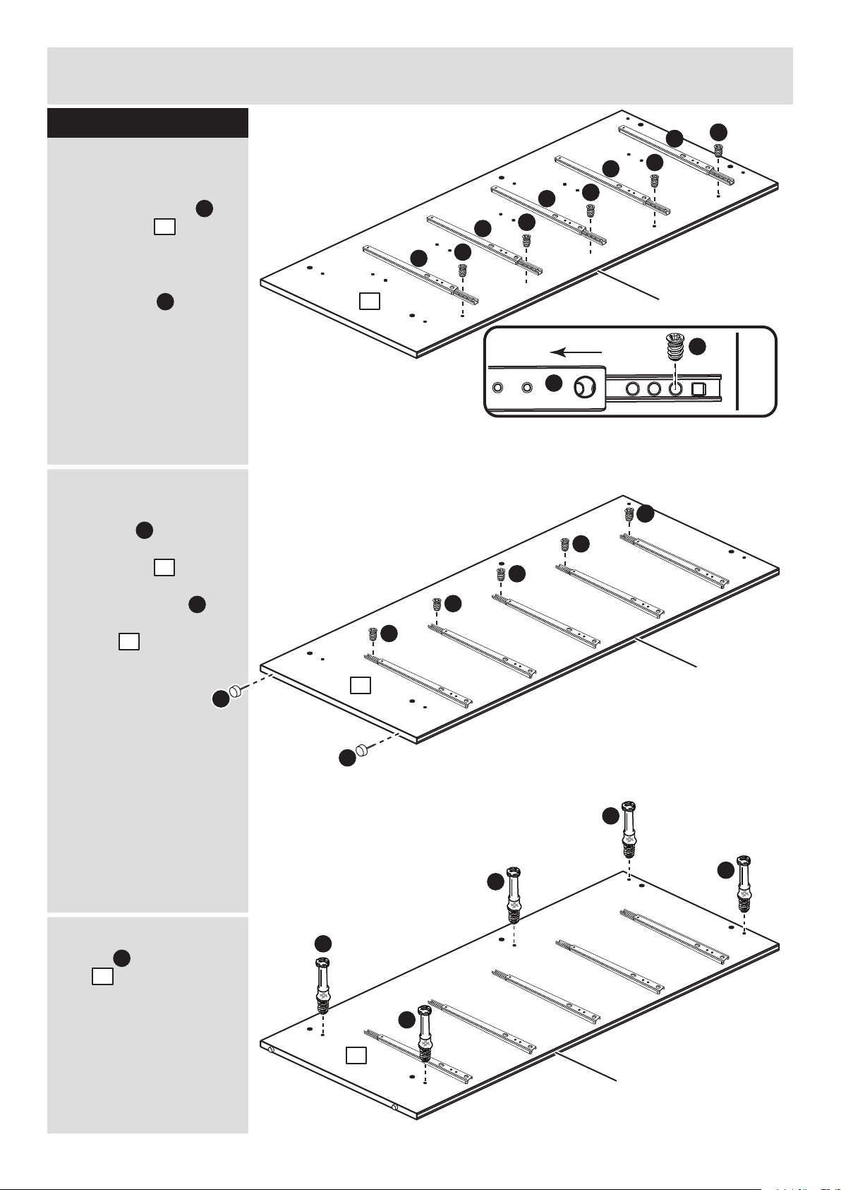
Step 9
I
J
I
J
I
J
Profiled
front edge
I
J
I
I
I
Profiled
front edge
Profiled
front edge
I
J
I
J
I
J
I
J
I
I
I
I
I
Profiled
front edge
B
B
B
B
B
N
N
2
2
2
Prepare the right side
a: Place 5 runners on
the right side . Slide
back the top of the
runner and use the 1st
hole from the front to fit
the 1st screw .
b: Slide the runner back
the other way and fit the
2nd screw into the
corresponding hole in
the right side .
Tap 2 plastic nails
into the bottom edge of
the side . .
c: Screw 5 metal
dowels into the right
side .
I
J
2
I
B
2
N
2
2
a:
b:
c:
Page 21
Finished
front edge
Profiled
front edge
A
A
Assembly Instructions
8
Step 9
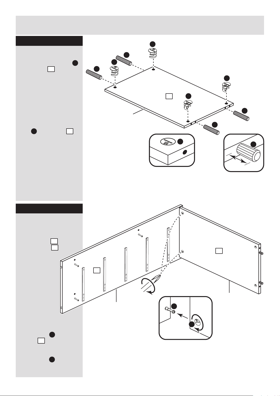
Prepare10the top
Tap 4 wooden dowels
into the top as
shown.
Note: Wooden dowels
must not stick out from
the edge by more than
10mm or they may
damage other panels.
Insert 4 large locking
nuts into the top
as shown.
Note: The arrow on the
locking nut must point
towards the hole in the
edge of the panel.
D
D
D
D
D
A
A
10mm
A
A
3
3
D
3
D
B
Join the right side and
top
Push the top onto
the right side as
shown.
Use a screwdriver to
tighten the 2 large
locking nuts fitted to
the top .
Note: Turn the large
locking nuts as far as
they will go - more than
1/2 a turn.
Step 11
3
2
3
2
D
D
3
Finished
front edge
Page 22
Assembly Instructions
9
Step 12
A
D
D
A
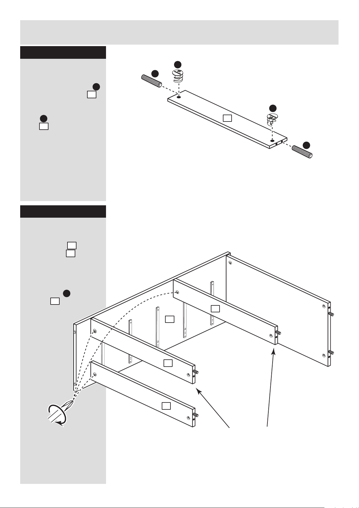
Prepare the rails
Tap 2 wooden dowels
into each of the rails .
Insert 2 large locking
nuts into each of the
rails .
A
4
D
4
4
Fit the rails
Push the rails onto
the right side as
shown.
Use a screwdriver to
tighten the 3 large
locking nuts fitted to
the rails .
Step 13
4
2
D
4
Note: Support
these rails until the
left side has been
fitted in the next
step.
2
4
2
4
4
x 3
Page 23
y
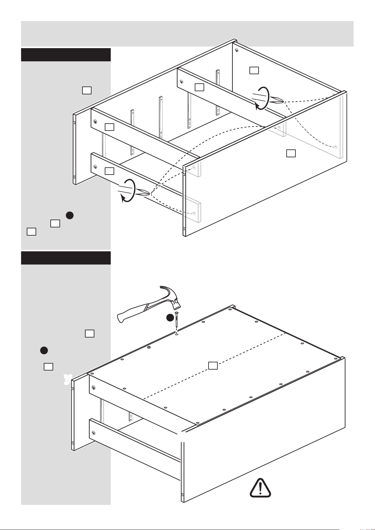
Fit the back
a: Square up the unit by
making sure that
measurement x to x
equals y to y.
b: Place the back
onto the unit.
Nail around the
outside edges of the
back .
Note: Nails should
be spaced about 150mm
apart.
Stand the unit up for
the next step.
Assembly Instructions
10
Step 14
Fit the left side
Push the left side
onto the assembly.
Use a screwdriver to
tighten the 5 large
locking nuts fitted to
the top and the rails
. .
D
1
3
4
10
C
The measurement from top corner X to bottom corner X must be
equal to the measurement from top corner Y to bottom corner Y
a:
10
Warning: The
unit is heavy.
Lift with care.
2
1
3
4
4
4
2
b:
C
x
y
y
10
Step 15
x
Page 24
Assembly Instructions
11
If you need help or have damaged or missing parts, call the Customer Helpline: 03456 400800
and quote the reference numbers on the component pages.
Argos Ltd, 489-499 Avebury Boulevard, Central Milton Keynes, MK9 2NW
ALR2993
Step 16
J
H
H
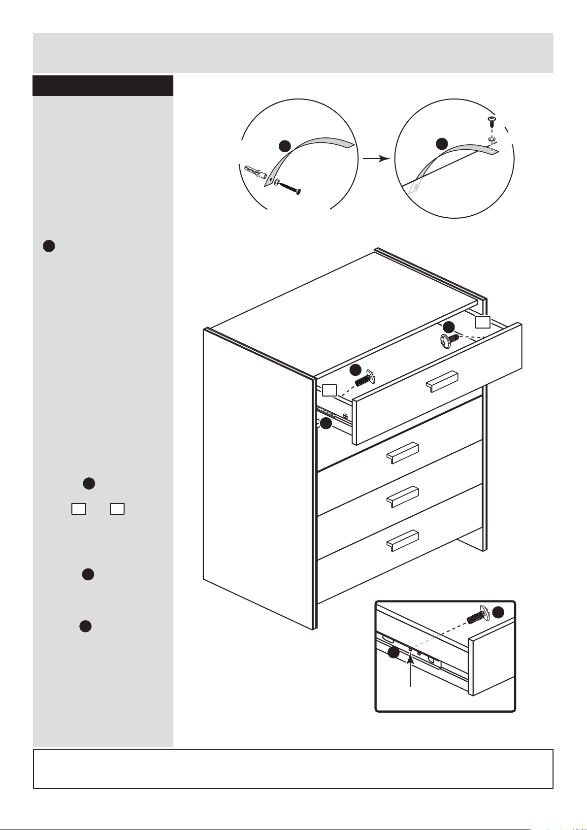
Fit the overbalance
protector kit and the
drawers
To prevent possible
overbalancing we
recommend that this unit
is secured to a suitable
wall by fitting of the
overbalance protector kit
. to the unit, or an
alternative fixing method
of your choice.
Wall fixings are not
supplied as they will
need to suit the wall
type.
Note: Take care when
drilling the wall that you
do not drill into any
pipes, wires etc.
If in doubt, consult an
expert.
Starting with the bottom
drawer, slide both the
runners forward and
locate the drawer
sides and
between them, lining up
the holes in the drawer
wrap with the 2nd
'threaded' holes in the
runners .
Working from the inside
of the drawer, insert 2
screws through the
drawer sides and out into
the 2nd threaded hole in
the runner.
Assembly is complete
H
J
J
2nd threaded
hole
J
H
6 7
6
7
Note: Do not overtighten
the screws.
If they catch on the
runner you may need to
loosen them slightly.
L
Attach the
strap to the unit
Attach the
strap to the wall
Wall fixing
(not supplied)
Washer
Strap
Strap
L
L
Example
Screw
(not supplied)
Washer
Screw
UNIT
Page 25
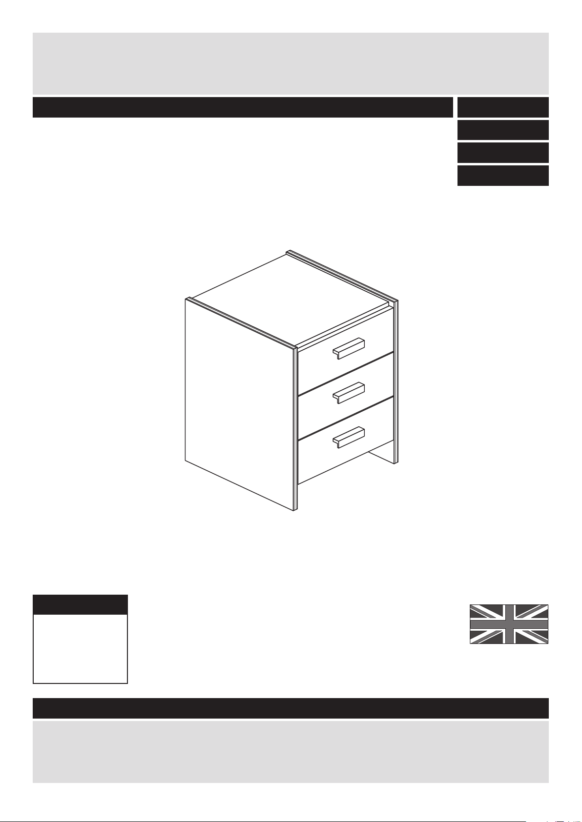
MADE IN
BRITAIN
If you need help or have damaged or missing parts, please visit www.argos-support.co.uk
or email: [email protected] (quoting your original order number)
Alternatively, call the Spares Helpline on: 0370 112 1928.
For any other queries please contact the Customer Helpline on: 0345 640 2020
Important - Please read these instructions fully before starting assembly
Dimensions
Width - 38cm
Depth - 39cm
Height - 58.5cm
Capella - 3 Drawer Bedside
Assembly Instructions - Please keep for future reference
Issue 2 - 18/09/15
395/8056
408/6192
448/1780
424/5263
Page 26
Safety and Care Advice
Important - Please read these instructions fully before starting assembly
• Warning: This unit weighs
approximately 13kgs.
Please lift with care.
• Check you have all the
components and tools listed on
pages 2 and 3.
• Remove all fittings from the
plastic bags and separate them
into their groups.
• Keep children and animals
away from the work area, small
parts could choke if swallowed.
• Parts of the assembly will be
easier with 2 people.
• Make sure you have enough
space to layout the parts before
starting.
• Do not stand or put weight on
the product, this could cause
damage.
• Assemble the item as close to
its final position (in the same
room) as possible.
• Assemble on a soft level
surface to avoid damaging the
unit or your floor (use opened
out unit carton).
• We do not
recommend the
use of power
drill/drivers for
inserting screws,
as this could damage the unit.
Only use hand screwdrivers.
• Safety note: If there is any
chance of this unit being pulled
over by children etc. it is
recommended that the unit is
secured to a wall using suitable
fixings (not supplied).
• Dispose of all packaging
carefully and responsibly.
1
Care and maintenance
• Only clean using a damp cloth
and mild detergent, do no use
bleach or abrasive cleaners.
• From time to time check that
there are no loose screws on
this unit.
• This product should not be
discarded with household
waste. Take to your local
authority waste disposal centre.
Note: If required the next page
can be cut out and used as
reference throughout the
assembly. Keep this page with
these instructions for future
reference.
Page 27
Components - Panels
If you need help or have damaged or missing parts, please visit www.argos-support.co.uk
or email: [email protected] (quoting your original order number)
Alternatively, call the Spares Helpline on: 0370 112 1928.
For any other queries please contact the Customer Helpline on: 0345 640 2020
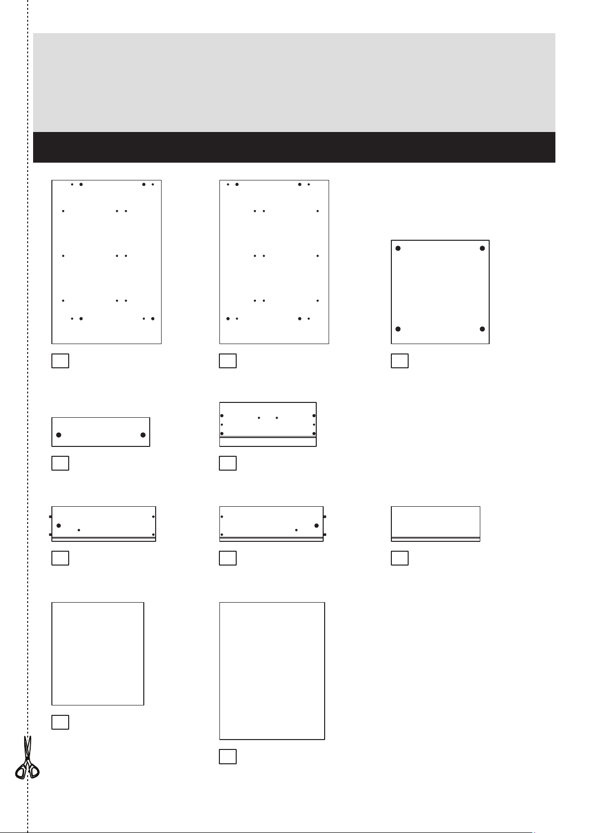
Please check you have all the panels listed below
When applicable, remove any
protective film before use
2
1
4
2 3
8
5
9
10
6 7
Left Drawer Side (W370-124LH)
(370 x 124mm) x 3
Right Drawer Side (W370-124RH)
(370 x 124mm) x 3
Top (D1001A)
(349 x 370mm)
Drawer Front (D1003A)
(345 x 157mm) x 3
Back (X490-375)
(490 x 375mm)
Rail (D1002A)
(349 x 103mm) x 2
Drawer Base (T328-367)
(328 x 367mm) x 3
Drawer Back (W317-124)
(317 x 124mm) x 3
Left Side (D1006A)
(584 x 390mm)
Right Side (D1007A)
(584 x 390mm)
Page 28
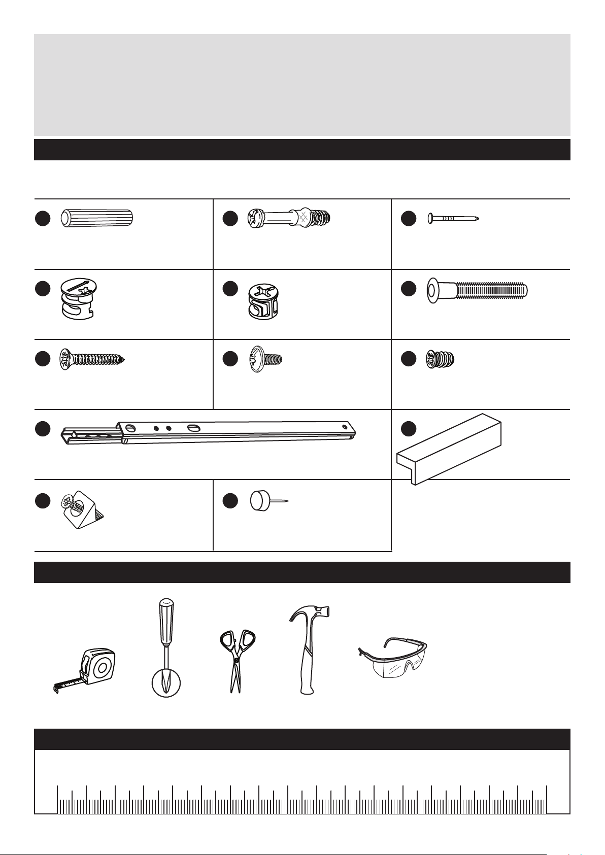
Please check you have all the fittings listed below
Note: The quantities below are the correct amount to complete the assembly. In some cases
more fittings may be supplied than are required.
Components - Fittings
If you need help or have damaged or missing parts, please visit www.argos-support.co.uk
or email: [email protected] (quoting your original order number)
Alternatively, call the Spares Helpline on: 0370 112 1928.
For any other queries please contact the Customer Helpline on: 0345 640 2020
Tools required
3
A
Wooden dowel (F22) x 8
B
Metal dowel (F901) x 14
D E
Large locking
nut (F900) x 8
G H I
K
Rule Scissors Hammer
Eye protection
(when using a
hammer or drill)
Cross-head
screwdriver
Small locking
nut (F3) x 6
C
Nail (F51) x 12
Ruler - Use this ruler to help correctly identify the screws
mm 10 20 30 40 50 60 70 80 90 100 110 120 130 140 150 160 170
J
Drawer runner (F1004) x 6 Handle (F930) x 3
25mm Screw (F50) x 6 9mm Screw (F74) x 6 9mm Screw (F73) x 12
F
Knock-in Peg (F171) x 12
M
Plastic Nail (F91) x 4
L
Wedgefix (F639) x 6
Page 29
5
Assembly Instructions
4
Step 1
x 3
x 3
x 3
x 3
B
B
E
E
E
E
6
7
Step 2
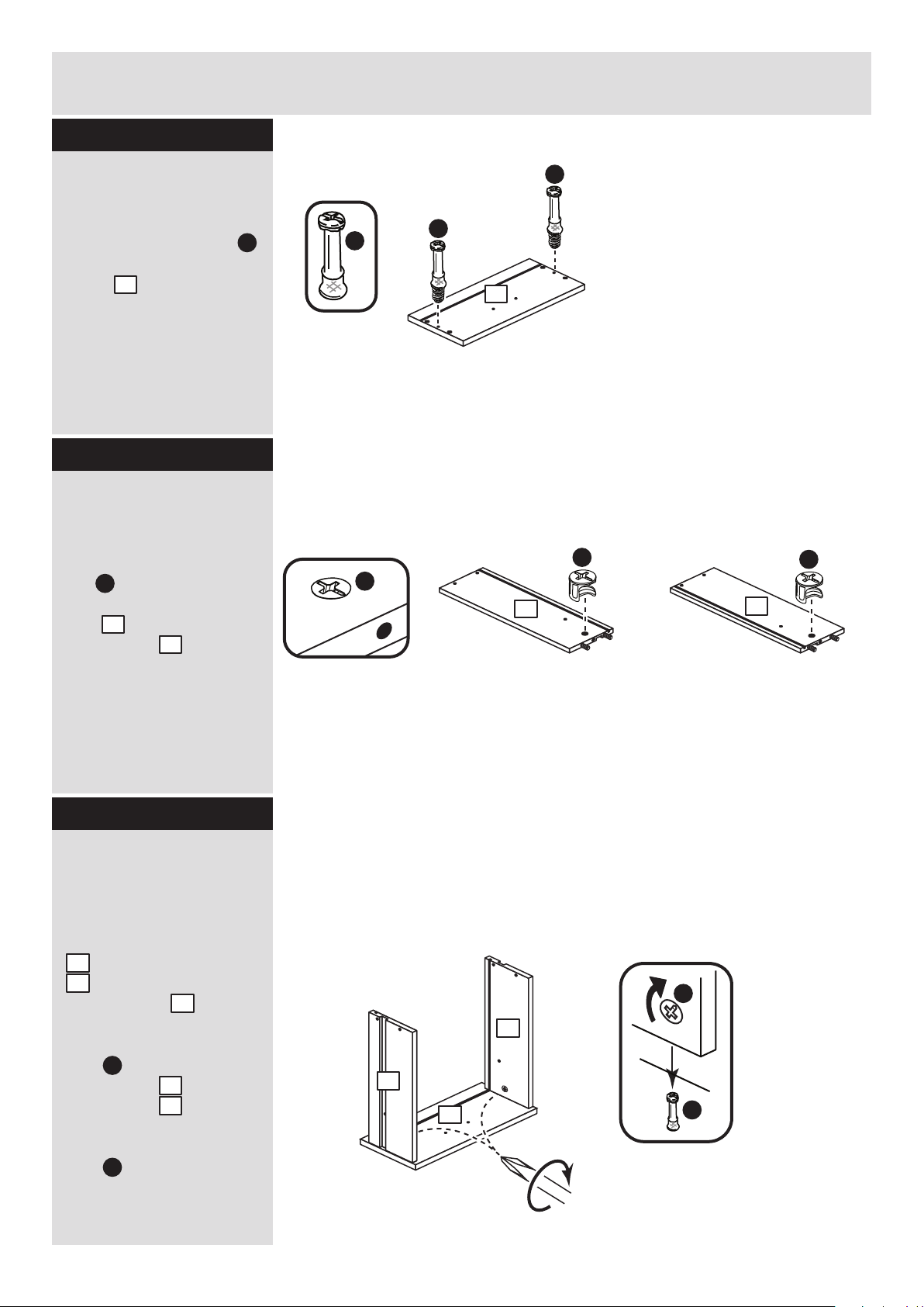
Prepare the 3 drawer
fronts
Screw 2 metal dowels
into each of the drawer
fronts .
Note: Tighten the metal
dowels up fully against
the panels.
B
5
Prepare the drawer
sides
Insert a small locking
nut into the hole
shown on the left drawer
side and the right
drawer side .
Note: The arrow on the
locking nut must point
towards the hole in the
edge of the panel.
Step 3
E
6
7
Attach the drawer
sides to the drawer
fronts
Push the left drawer sides
. and right drawer sides
. onto the back of the
drawer fronts .
Turn the small locking
nuts on the left
drawer side and right
drawer side .
Note: Turn the locking
nuts clockwise to
secure panels - more
than 1/2 a turn.
6
7
5
E
E
6
7
6
7
B
B
5
Page 30
5
Assembly Instructions
5
Step 4
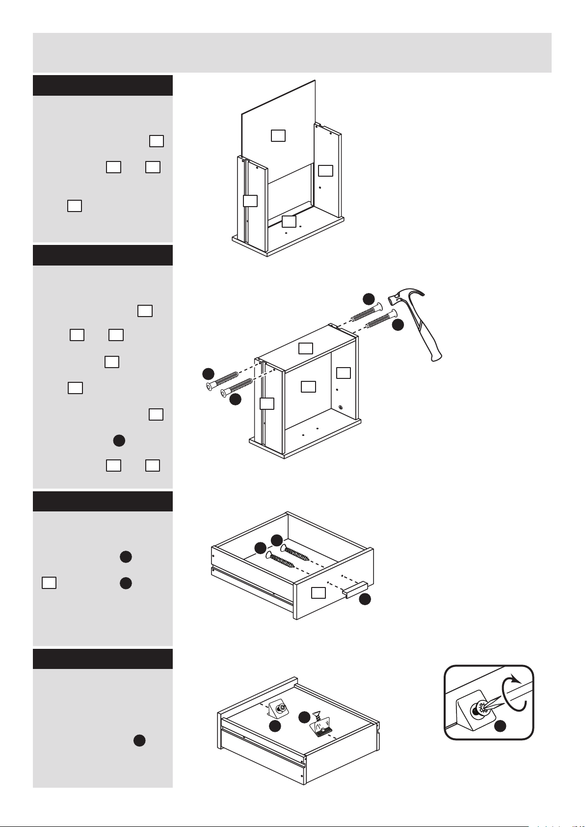
F
F
Fit the drawer base
Slide the drawer base
down the grooves in the
drawer sides and
and down into the
groove in the drawer
front .
Step 5
Fit the drawer back
Fit the drawer back
between the drawer
sides and .
Make sure that the
drawer base fits into
the groove in the drawer
back .
Hold the drawer back
in position and tap the
knock-in pegs
through the holes in the
drawer sides and .
Step 6
9
6 7
5
8
6 7
9
8
8
F
Attach the handles
Attach a handle to
each of the drawer fronts
. using screw .
Note: Do not
overtighten the screw.
K
G
5
6 7
Step 7
Fit the wedgefixes
Turn the drawer
assemblies over and
slide 2 wedgefixes
into the front and back
grooves, as shown, and
tighten up the screws.
L
x 3
x 3
x 3
F
F
x 3
L
L
L
9
6
8
6
7
9
7
K
G
G
5
Page 31
Profiled
front edge
Profiled
front edge
Profiled
front edge
Assembly Instructions
6
Step 8
Profiled
front edge
I
J
I
J
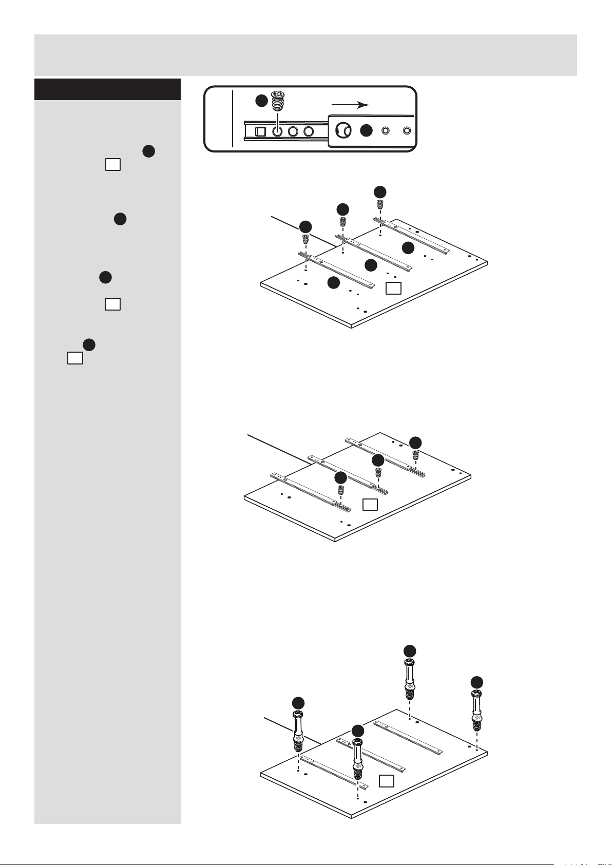
Prepare the left side
a: Place 3 runners on
the left side . Slide
back the top of the
runner and use the 1st
hole from the front to fit
the 1st screw .
b: Slide the runner back
the other way and fit the
2nd screw into the
corresponding hole in
the left side .
c: Screw 4 metal
dowels into the left
side .
a:
b:
c:
1
I
B
1
1
1
1
1
B
B
B
B
I
J
I
I
I
I
J
I
J
Page 32
Assembly Instructions
7
Step 9
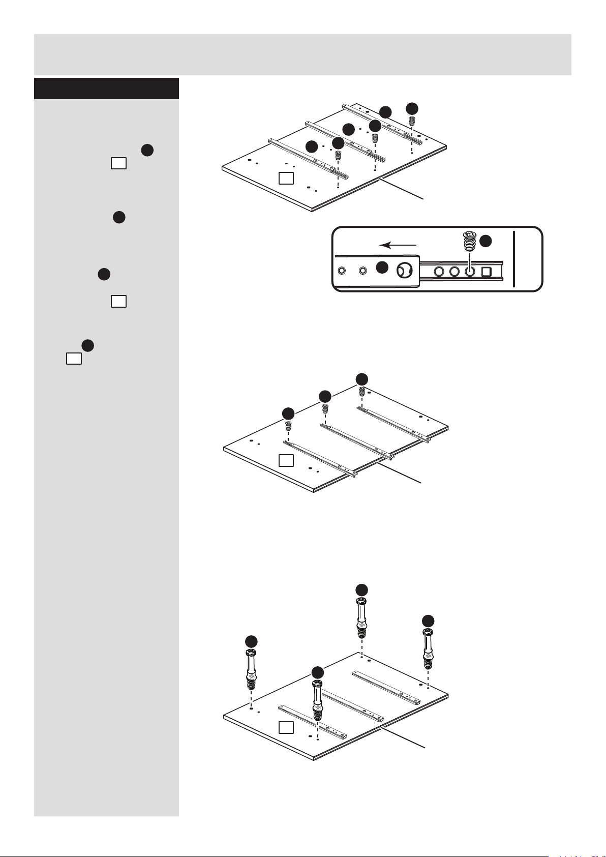
Prepare the right side
a: Place 3 runners on
the right side . Slide
back the top of the
runner and use the 1st
hole from the front to fit
the 1st screw .
b: Slide the runner back
the other way and fit the
2nd screw into the
corresponding hole in
the right side .
c: Screw 4 metal
dowels into the right
side .
Profiled
front edge
I
J
I
J
2
I
B
2
2
a:
b:
c:
I
J
I
I
I
I
J
I
J
Profiled
front edge
Profiled
front edge
Profiled
front edge
B
B
B
B
2
2
2
Page 33
A
Finished
front edge
Finished
front edge
A
A
Assembly Instructions
8
Step 10
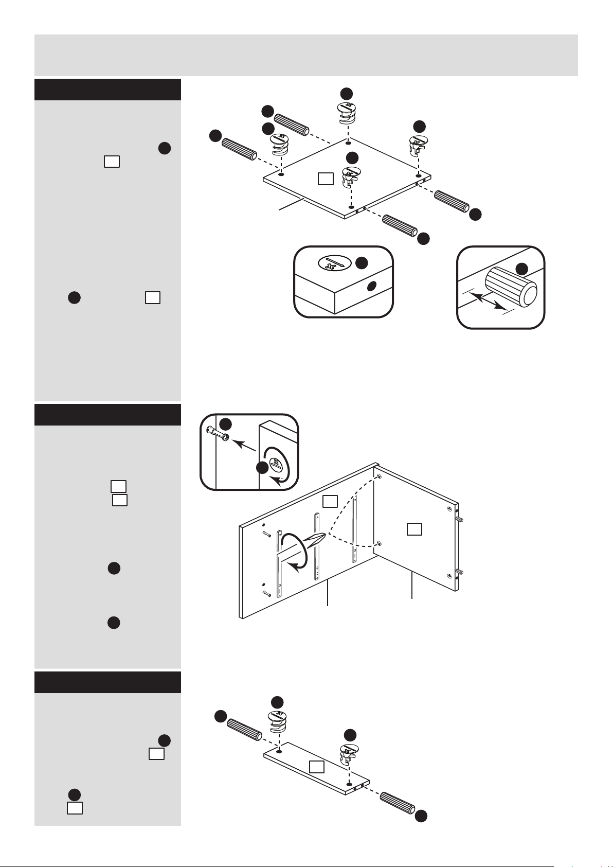
Prepare the top
Tap 4 wooden dowels
into the top as
shown.
Note: Wooden dowels
must not stick out from
the edge by more than
10mm or they may
damage other panels.
Insert 4 large locking
nuts into the top
as shown.
Note: The arrow on the
locking nut must point
towards the hole in the
edge of the panel.
D
10mm
A
A
3
3
D
Fit the top to the right
side
Push the top onto
the right side as
shown.
Use a screwdriver to
tighten the 2 large
locking nuts fitted to
the top .
Note: Turn the large
locking nuts as far as
they will go - more than
1/2 a turn.
Step 11
3
2
D
D
D
D
D
D
A
A
Finished
front edge
3
B
D
3
2
Prepare the 2 rails
Tap 2 wooden dowels
into each of the rails .
Insert 2 large locking
nuts into each of the
rails .
A
4
4
x 2
Step 12
D
D
A
D
4
Page 34
Assembly Instructions
9
Step 13
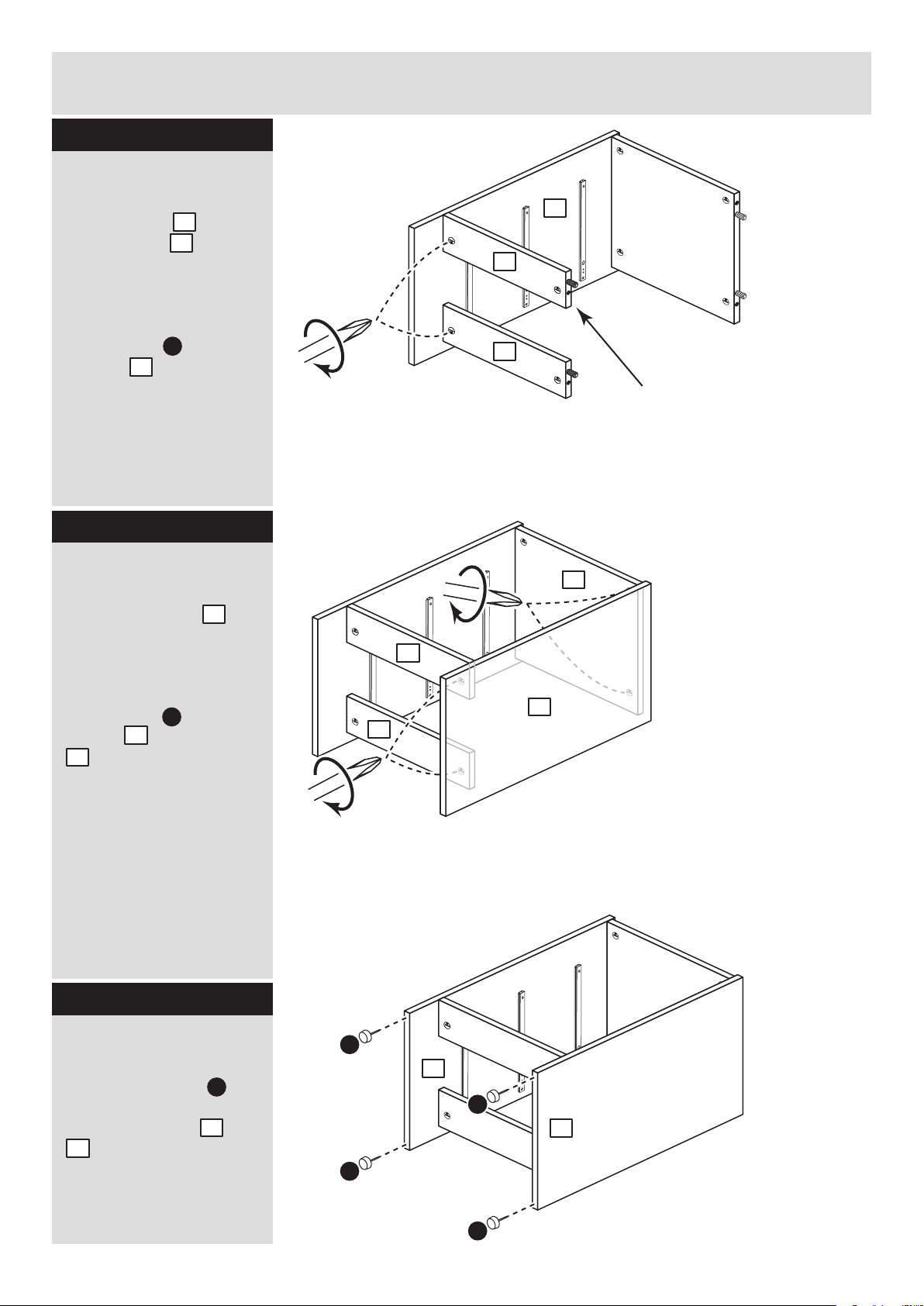
Fit the 2 rails
Push the rails onto
the right side as
shown.
Use a screwdriver to
tighten the 2 large
locking nuts fitted to
the rails .
4
2
D
4
Support this rail until
the left side has been
fitted in the next step.
Fit the left side
Push the left side
onto the assembly.
Use a screwdriver to
tighten the 4 large
locking nuts fitted to
the top and the rails
.
D
1
3
4
Step 14
4
2
4
4
4
1
3
Fit the 4 plastic nails
Tap 2 plastic nails
into the bottom edge of
each of the sides and
. .
M
1
2
M
M
M
M
Step 15
1
2
Page 35
Assembly Instructions
10
Step 16
Step 17
b:
C
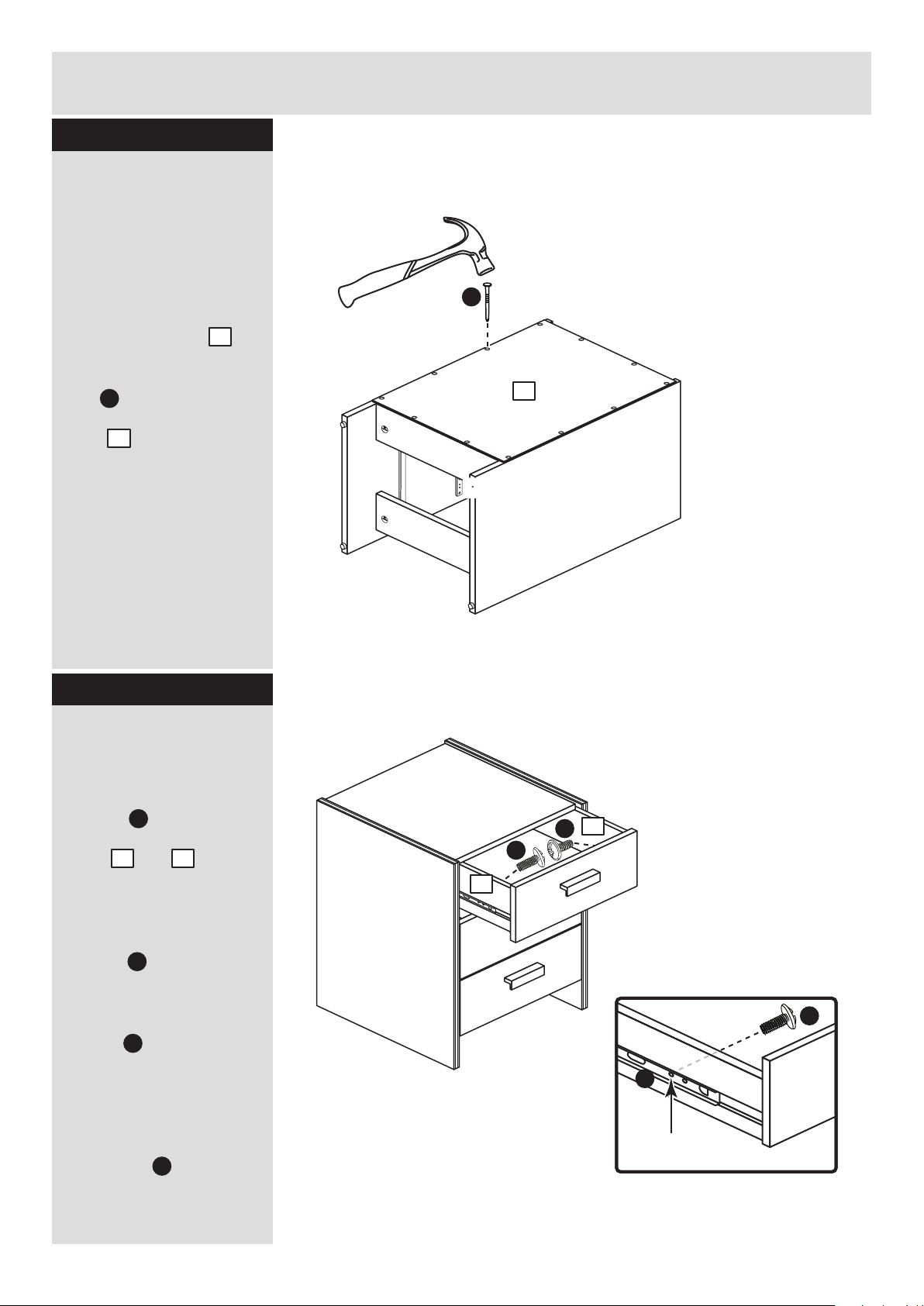
Fit the back
a: Square up the unit by
making sure that
measurement x to x
equals y to y.
b: Place the back
onto the unit.
Nail around the
outside edges of the
back .
Note: Nails should be
spaced about 150mm
apart.
Stand the unit up for
the next step.
10
C
The measurement from top corner X to bottom corner X must be
equal to the measurement from top corner Y to bottom corner Y
a:
10
yy
yy
xx
10
xx
Fit the drawers
Starting with the bottom
drawer, slide both the
runners forward and
locate the drawer
sides and
between them, lining up
the holes in the drawer
wrap with the 2nd
'threaded' holes in the
runners .
Working from the inside
of the drawer, insert 2
screws through the
drawer sides and out into
the 2nd threaded hole in
the runner.
Note: Do not overtighten
the screws .
If they catch on the
runner you may need to
loosen them slightly.
H
J
J
H
2nd threaded
hole
J
H
6 7
H
H
6
7
Page 36
Assembly Instructions
If you need help or have damaged or missing parts, please visit www.argos-support.co.uk
or email: [email protected] (quoting your original order number)
Alternatively, call the Spares Helpline on: 0370 112 1928.
For any other queries please contact the Customer Helpline on: 0345 640 2020
11
ALR3161
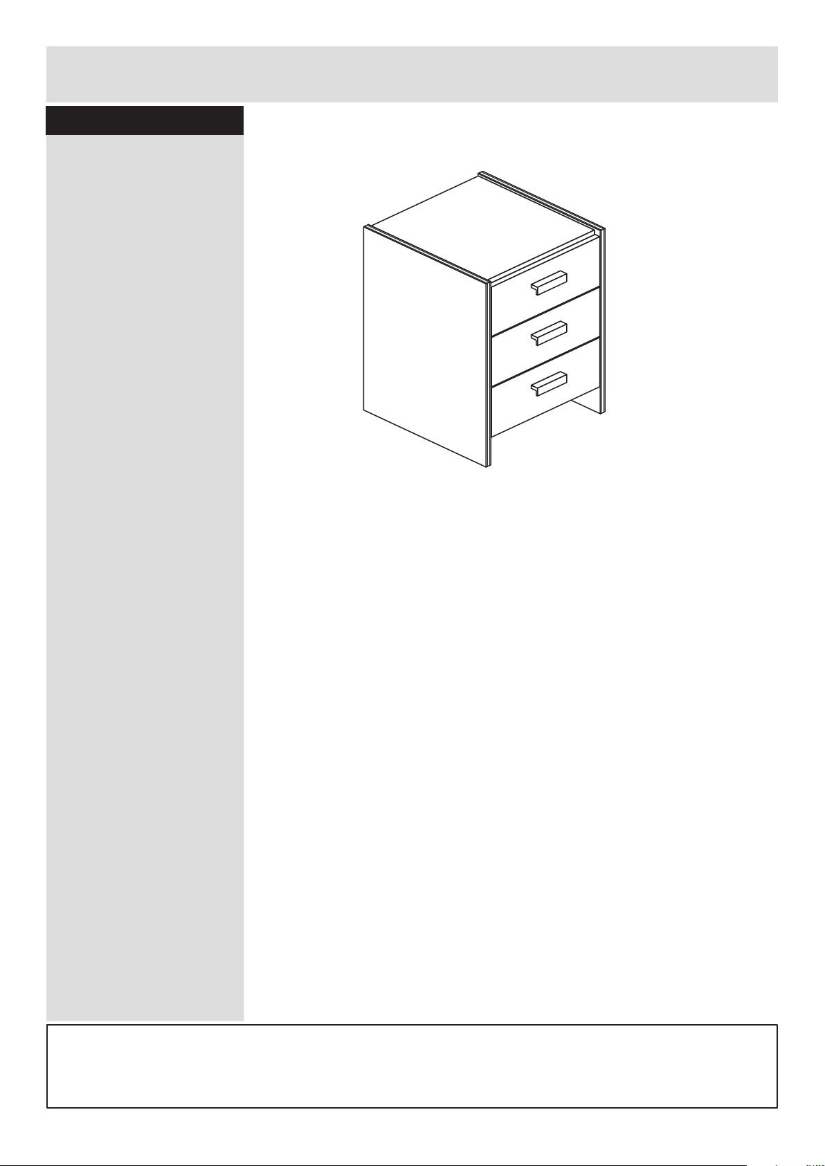
Step 18
Assembly is complete
 Loading...