

Page 1
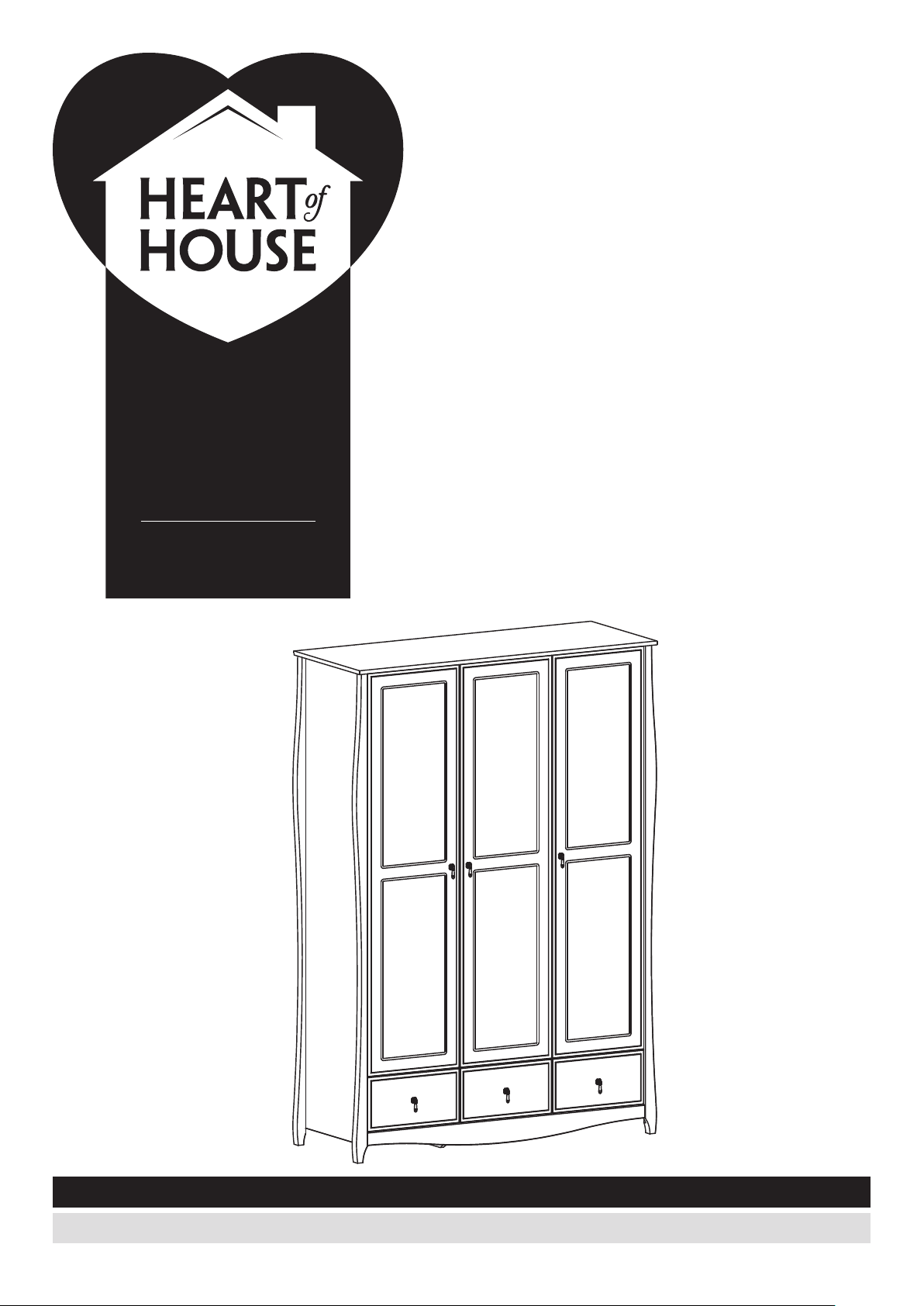
osaka
abingdon
23465758
4020897
dimensions
width: 40,0 cm
width: 131.5 cm
depth: 40,0 cm
depth: 50.0 cm
height 59,6 cm
height: 189.9 cm
assembly instructions - please keep for future reference
if you need help or have damaged or missing parts, call the argos customer helpline: 03456 400 800
350807-01
issue 1 - 08-06-2015
Page 2
safety and care advice
!
important - please read these instructions fully before starting assembly
• assembly should be carried
out by a competent adult
only.
• check you have all the
components and tools listed
on pages 2 and 3.
• do not use this product if
any components are missing
or damaged.
• remove all fittings from the
plastic bags and separate
them into their groups.
• keep children and animals
away from the work area,
small parts could choke if
swallowed.
care and maintenance
• only clean using a damp
cloth and mild detergent, do
no use bleach or abrasive
cleaners.
• make sure you have enough
space to layout the parts
before starting.
• do not stand or put weight
on the product, this could
cause damage.
• assemble the item as close
to its final position (in the
same room) as possible.
• assemble on a soft level
surface to avoid damaging
the unit or your floor.
• parts of the assembly will
be easier with 2 people.
• regularly check fastenings
to ensure they are tightened.
• we do not recommend the
use of power drill/drivers
i
nserting screws
damage the unit. Only use
hand screwdrivers.
• dispose of all packaging
carefully and responsibly
• made for home retail group,
milton keynes.
• this product should not be
discarded with household
waste.
take to your local authority
waste disposal centre.
, as this could
for
.
note: if required the next
page can be cut out and
used as reference
throughout the assembly.
keep this page with these
instructions for future
reference.
1
Page 3
if you have damaged or missing components, call
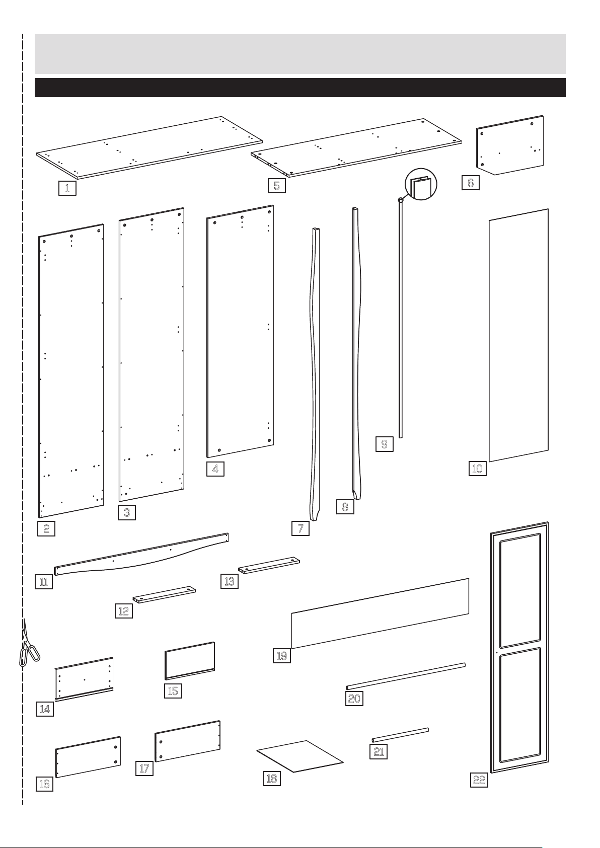
components - panels
the argos customer helpline: 03456 400 800
please check you have all the panels listed below
5
top
1
(130,4 cm x 50 cm)
bottom
(121,5 cm x 46,4 cm)
x
6
divider, small
(31,9 cm x 46,4 cm)
2
2
side, left
(182,1 cm x 45 cm)
11
front rail
(121,5 cm x 9,2 cm)
14
drawer front
(40,1 cm x 20,9 cm)
3
side, right
(182,1 cm x 45 cm)
back rail, side
12
(39,8 cm x 7 cm)
x
3
x
2
15
drawer back
(34 cm x 18,2 cm)
4
divider, large
(155,0 cm x 46,4 cm)
back rail
13
(38,9 cm x 7 cm)
x
3
7
post, left
(188,4 cm x 5 cm)
19
back, small
(124,6 cm x 22,9 cm)
9
8
post, right
(188,4 cm x 5 cm)
x
2
20
hanging rail
(79,3 cm x 2,2 cm)
h-profile
(154,5 cm x 1,7 cm)
x
2
10
x
back
(156,5 cm x 41,5 cm)
3
16
drawerside, left
(45 cm x 18,2 cm)
350807-03
17
drawerside, right
(45 cm x 18,2 cm)
x
3
x
hanging rail, small
21
3
18
drawer bottom
(35,0 cm x 44,7 cm)
x
(38,8 cm x 2,2 cm)
3
door
22
x
(155,3 cm x 40,1 cm)
3
2
Page 4
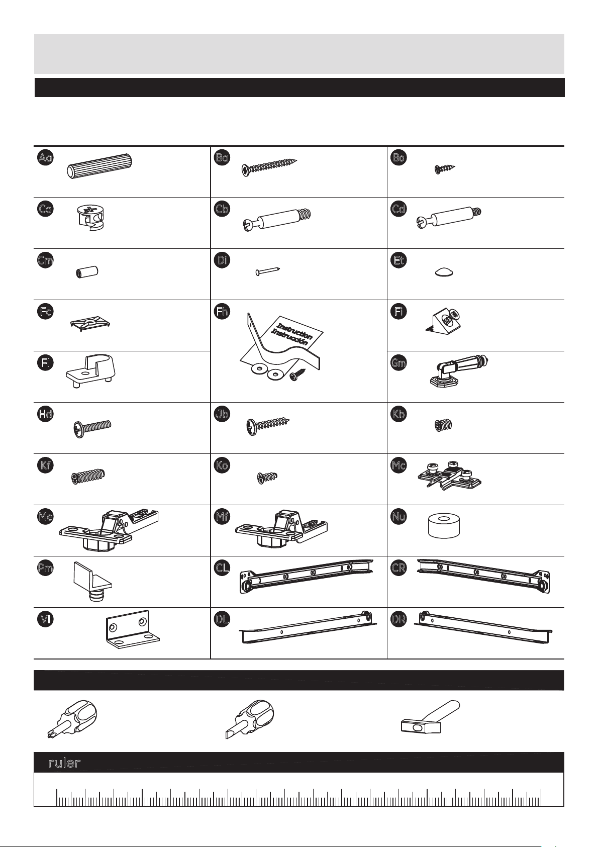
components - ttings
please check you have all the panels listed below
note: the quantities below are the correct amount to complete the assembly. In some cases more ttings
may be supplied than are required.
Aa
ø7.8 x 40mm wooden dowel x
Ca
ø15 x 10.5mm cam x
Cm
m4 / ø5 x 12mm threaded tube x
Fc
back fitting - 14 x 19mm x
Fl
support for hanger rail - 15mm x
m4 x 20mm screw xHd6
Kf
41
12
4
39
ø3.5 x 35mm screw xBa18
Cb
ø5 x 8, cc34mm bolt x
4
1.2 x 15mm nail xDi50
Fh
wall strap and instruction x 1
ø4 x 25mm screw xJb20
Ko
33
ø3 x 12mm screw xBo46
Cd
m4, cc34mm bolt x
self adhesive bumper, ø10 x 3mm xEt6
back fitting w. ø3.5 x 15mm screw xFi6
Gm
54mm handle x
Kb
ø5.8 x 8mm screw x
Mc
8
6
12
ø5.8 x 19mm Screw x
Me
ø26mm cup hinge x
Pm
door stop x
Vl
44 x 23 x 23mm angle x
6
6
ø4,2 x 9,5mm screw x
Mf
ø26mm cup hinge x
3
CL
450mm drawer runner, left, side x
DL
2
450mm drawer runner, left x
8
6
0mm crossplate x
ø18 x 9mm Spacer xNu6
CR
3
450mm drawer runner, right, side x
DR
450mm drawer runner, right x
3
tools required
phillips screwdriver
(medium & large)
flatblade screwdriver
(medium)
ruler - use this ruler to help correctly identify the screws
9
3
3
hammer
17060 16040 90 15013070 120100 14011050 803020100
3
350807-04
Page 5
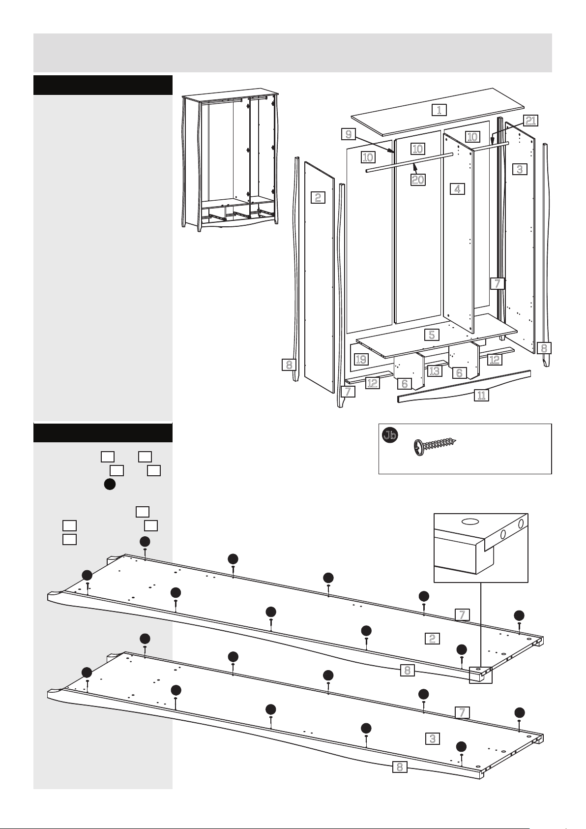
assembly instructions
step 1
assembly of the
wardrobe.
1
21
9
10
10
10
3
20
4
2
7
5
8
8
19
13
6
12
7
6
12
11
step 1.1
x the posts 7 and 8
2
onto the sides
using screws
holes indicated.
the top of the posts
8
and
and
and the sides 2
3
must
be ush.
Jb
Jb
and 3
Jb
into the
7
Jb
Jb
ø4 x 25mm screw xJb20
Jb
Jb
Jb
Jb
Jb
Jb
7
Jb
2
Jb
7
3
Jb
Jb
Jb
Jb
Jb
Jb
8
Jb
Jb
350807-05
8
4
Page 6
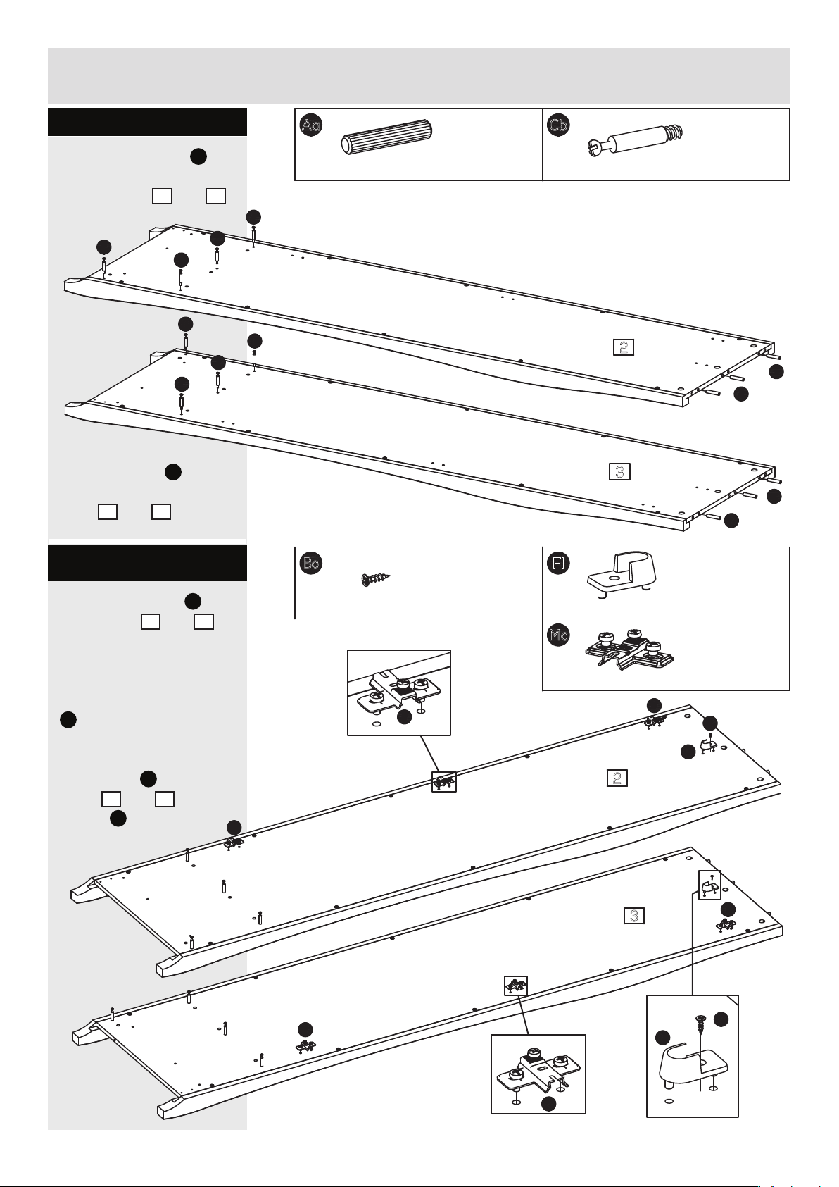
assembly instructions
step 1.2
knock the dowels Aa
into the holes indicated
on the sides
Cb
use a small
hammer.
screw the bolts Cb into
the holes indicated on the
sides
2
2 and 3.
Cb
Cb
Cb
Cb
Cb
and 3.
Cb
Cb
Aa
ø7.8 x 40mm wooden dowel x
Cb
6
ø5 x 8, cc34mm bolt x
8
2
Aa
Aa
3
Aa
Aa
step 1.3
x the crossplates Mc
to the sides
2
using the pre-mounted
screws.
position the crossplates
Mc
exactly as shown.
x the supports for
hangerrails
sides
screws
Fl
to the
2
and 3 using
Bo
.
and
3
Mc
ø3 x 12mm screw xBo2
Mc
Fl
support for hanger rail - 15mm x
2
Mc
0mm crossplate x
6
Mc
Bo
Fl
2
3
Mc
Mc
Mc
Fl
5
Bo
350807-06
Page 7
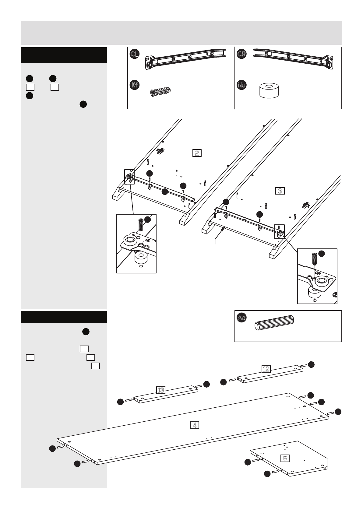
assembly instructions
step 1.4
x the drawer runners
CL
and CR to the sides
2
and 3 using screws
Kf
through the holes
Nu
and the spacers
indicated.
see details.
as
CL
450mm drawer runner, left, side x
Kf
ø5.8 x 19mm Screw x
6
2
Kf
CL
Kf
Kf
CR
1
450mm drawer runner, right, side x
ø18 x 9mm Spacer xNu6
3
Kf
Kf
1
step 1.5
knock the dowels Aa
into the holes indicated
on the back rails
13
, the large divider 4
and the small dividers
using a small hammer.
12 and
6
note the hole!
bottom end of
Kf
right hand side
Aa
ø7.8 x 40mm wooden dowel x
x
Aa
2
Aa
Aa
Aa
12
13
x
Aa
1
15
Aa
Aa
350808-07
Aa
Aa
4
Aa
Aa
6
x
2
6
Page 8
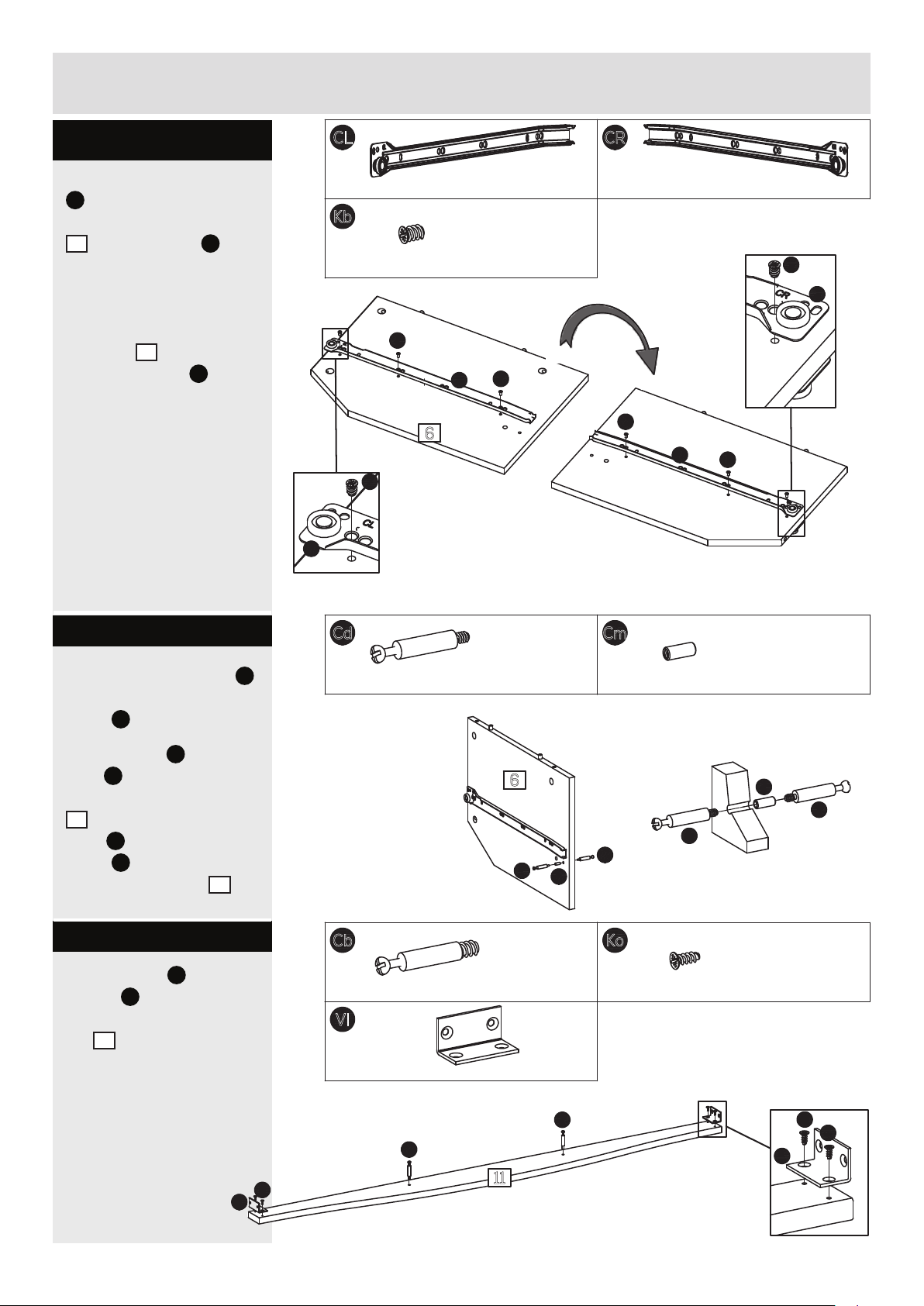
assembly instructions
step 1.6
x the drawer runner
CL
to the right hand
side of the dividers
6
using screws Kb
through the holes as
indicated.
turn around the
6
dividers
drawer runner
the left hand side of
the dividers
see details.
and x the
CR
to
CL
450mm drawer runner, left, side x
Kb
ø5.8 x 8mm screw x
12
Kb
Kb
CL
6
Kb
CL
x
CR
2
450mm drawer runner, right, side x
Kb
CR
Kb
Kb
2
CR
2
step 1.7
screw one of the bolts Cd
into each of the threaded
Cm
tubes
push the bolt
tube
.
Cd
+ the
Cm
into the holes
indicated on the dividers
6
and x them using
Cd
bolts
tubes
side of the dividers
into the threaded
Cm
from the other
6
.
step 1.8
x the angles Vl using
Ko
screws
indicated on the front
rail
into the holes
11
.
Cd
m4, cc34mm bolt x
4
6
Cd
Cb
ø5 x 8, cc34mm bolt x
2
Vl
44 x 23 x 23mm angle x
Cm
Cm
m4 / ø5 x 12mm threaded tube x
Cd
Cd
x
2
Ko
ø4.2 x 9.5mm screw x
2
2
Cm
Cd
4
Cb
Cb
Ko
Vl
11
7
Ko
Ko
Vl
350807-08
Page 9
assembly instructions
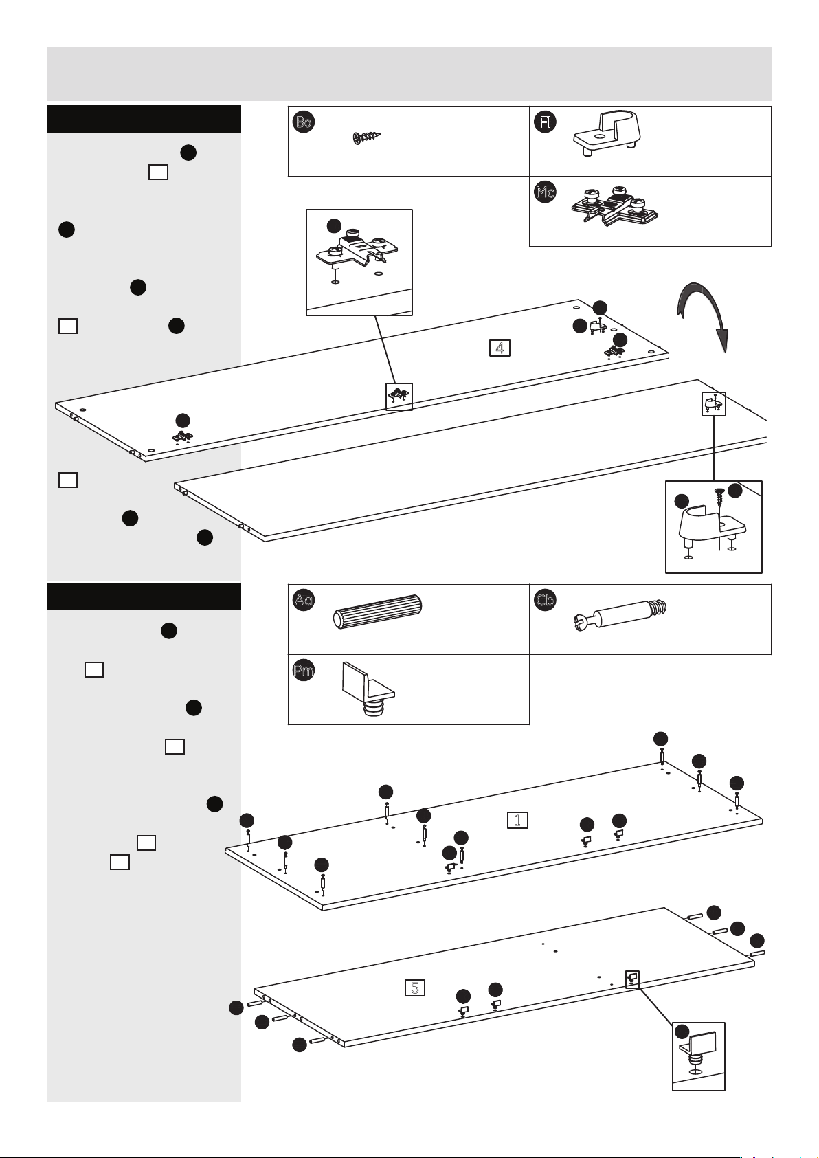
step 1.9
x the crossplates Mc
4
to the divider
the pre-mounted screws.
position the crossplates
Mc
exactly as shown.
x the support for
hangerrail
hand side of the divider
4
using screws Bo.
turn around the
divider
4
and x
the support for
hangerrail
other side using screws
using
Fl
to the left
Fl
to the
Mc
Bo
.
ø3 x 12mm screw xBo2
Mc
Fl
support for hanger rail - 15mm x
Mc
0mm crossplate x
Bo
Fl
4
Mc
2
3
Fl
Bo
step 1.10
screw the bolts Cb into
the holes indicated on the
1
top
knock the dowels Aa
into the holes indicated
on the bottom
a small hammer.
push the door stops
into the holes indicated
on the top
bottom
.
5
using
Pm
1
and the
5
.
Aa
ø7.8 x 40mm wooden dowel x
Cb
6
ø5 x 8, cc34mm bolt x
9
Pm
door stop x
Cb
Cb
Cb
Cb
6
Cb
Pm
Cb
Cb
Cb
Cb
1
Pm
Pm
Aa
Aa
Aa
5
Aa
Aa
Aa
Pm
Pm
Pm
350807-09
8
Page 10
assembly instructions
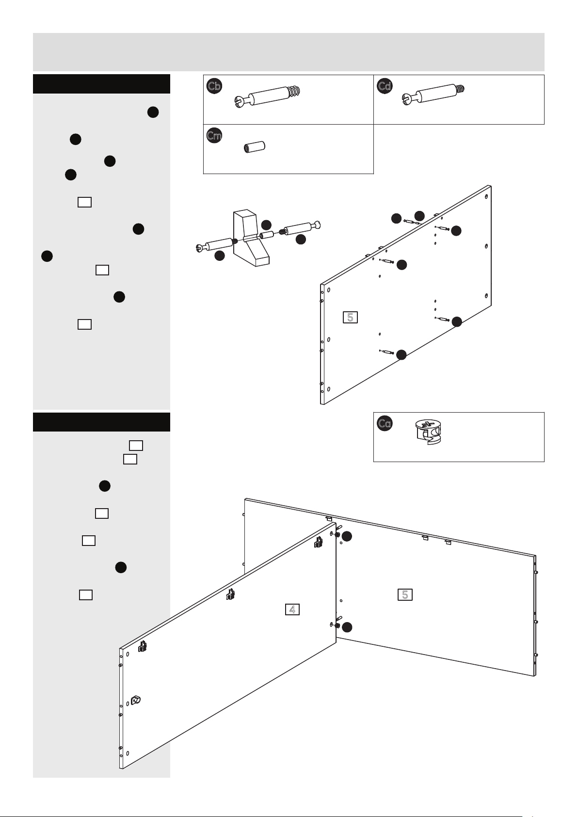
step 1.11
screw one of the bolts Cd
into each of the threaded
Cm
tubes
push the bolt
tube
indicated on the
bottom
x them using bolts
into the threaded tubes
Cm
the bottom
screw the bolts
the holes indicated on the
bottom
.
Cd
+ the
Cm
into the holes
5
.
Cd
from the other side of
5
.
Cb
into
5
.
Cb
ø5 x 8, cc34mm bolt x
2
Cm
m4 / ø5 x 12mm threaded tube x
Cm
Cd
Cd
5
Cd
m4, cc34mm bolt x
2
Cd
Cb
Cb
4
Cm
Cd
Cd
step 1.12
place the divider 4
onto the
push cams Ca into the
holes indicated on
the
pointing towards the
bottom
turn the cams
right to x the
divider
bottom 5.
divider 4,
5
.
4
.
arrows
Ca
to the
Ca
ø15 x 10.5mm cam x
Ca
2
5
4
Ca
9
350807-10
Page 11
assembly instructions
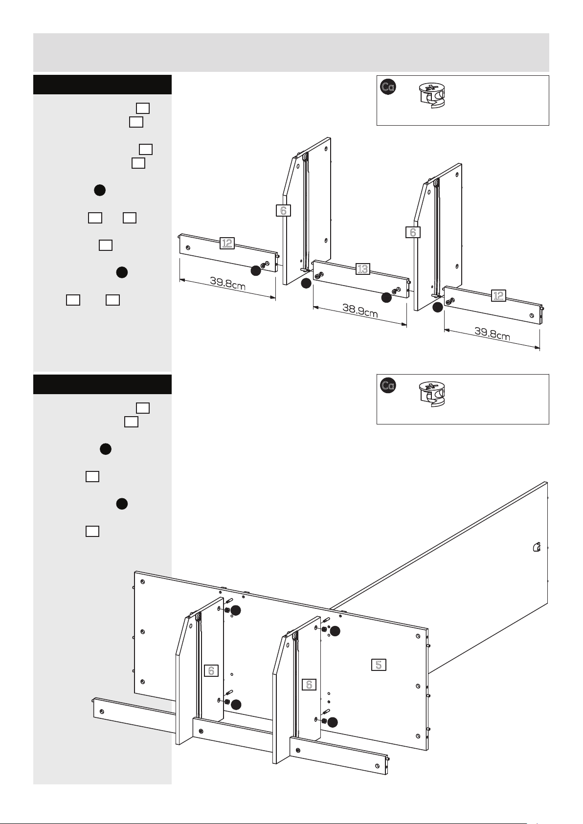
step 1.13
place the dividers 6
onto the
place the
onto the dividers
push cams Ca into the
holes indicated on the
back rails
arrows pointing towards
the dividers
turn the cams Ca to the
right to x the back
rails
back rail 13 .
back rails 12
12
and13,
6
12
and 13.
6
.
.
12
Ca
Ca
ø15 x 10.5mm cam x
4
6
6
13
Ca
Ca
Ca
12
step 1.14
place the dividers 6
onto the
push cams
holes indicated on the
dividers
turn the cams
right to x the
dividers
bottom 5.
Ca
into the
6
.
Ca
to the
6
.
Ca
ø15 x 10.5mm cam x
Ca
Ca
6
5
4
6
350807-11
Ca
Ca
10
Page 12
assembly instructions
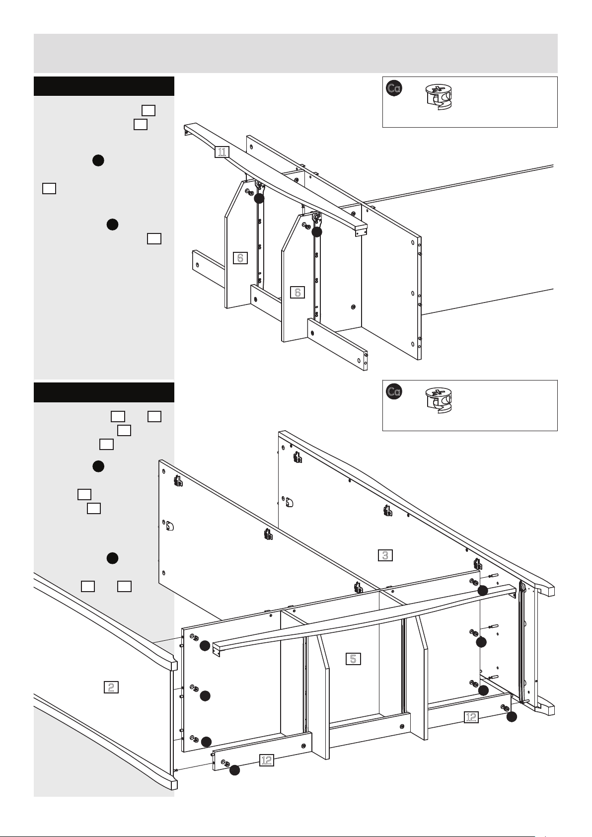
step 1.15
place the front rail
onto the dividers 6.
push cams Ca into the holes
indicated on the dividers
6
arrows pointing
towards the front rail.
turn the cams
Ca
right to x the front rail
11
to the
11
.
11
Ca
ø15 x 10.5mm cam x
Ca
Ca
2
6
6
step 1.16
place the sides 2 and 3
5
onto the bottom
the back rail
push cams
12
Ca
holes indicated on the
5
bottom
back rails
and the
12
, arrows
pointing towards the
sides.
turn the cams
right to x the sides
2
and 3.
and
.
into the
Ca
to the
Ca
Ca
ø15 x 10.5mm cam x
8
3
Ca
Ca
5
11
2
Ca
Ca
12
Ca
Ca
12
Ca
350807-12
Page 13
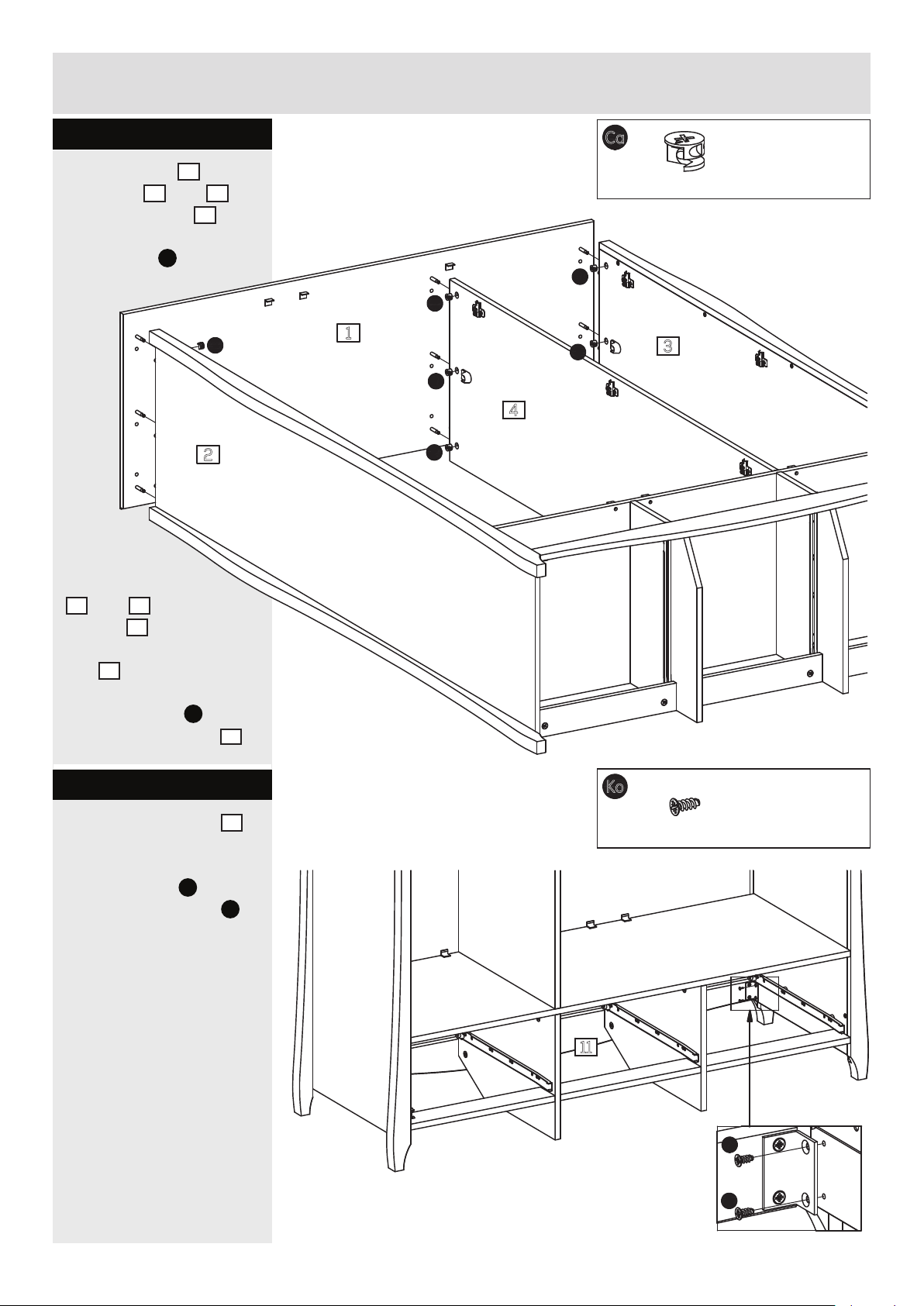
assembly instructions
step 1.17
place the top 1 onto
2
4
, arrows
.
and 3
4
Ca
into
Ca
2
.
the sides
and the divider
push cams
the holes
indicated
on the sides
2
and 3 and the
divider
pointing towards the
1
top
Ca
ø15 x 10.5mm cam x
Ca
Ca
9
1
Ca
Ca
3
4
Ca
turn the cams
Ca
to the
right to x the top
step 1.18
place the front rail
as shown.
x the angles
sides using screws
see detail.
Vl
to the
11
Ko
.
1
Ko
ø4,2 x 9,5mm screw x
4
.
11
Ko
350807-13
Ko
12
Page 14
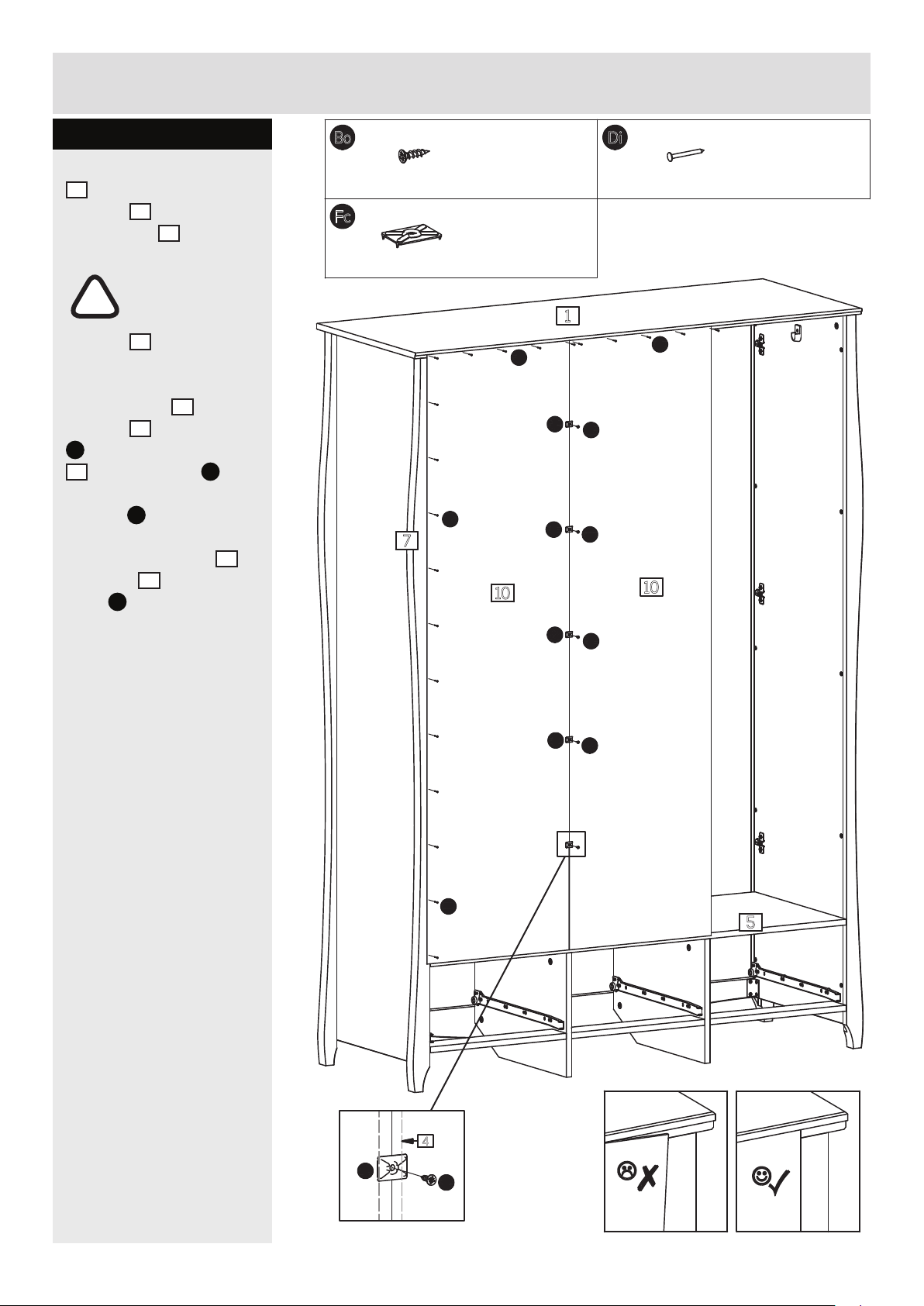
assembly instructions
step 1.19
place two of the backs
10
into the rabbet on
1
the top
the divider
!
the top
sides is 90°.
x the backs
the top
Di
and to the divider
4
using screws Bo
through the back
ttings
nally x the back
the post
nails
hammer.
and onto
4
.
important!
make sure the
angle between
1
and the
10
to
1
using nails
Fc
.
7
using
Di
and a small
10
to
Bo
ø3 x 12mm screw x
5
Fc
back fitting - 14 x 19mm x
Di
7
10
1.2 x 15mm nail xDi21
5
1
Di
Fc
Bo
Fc
Bo
Di
10
Fc
Bo
Fc
Fc
Bo
Di
5
4
Bo
13
350807-14
Page 15
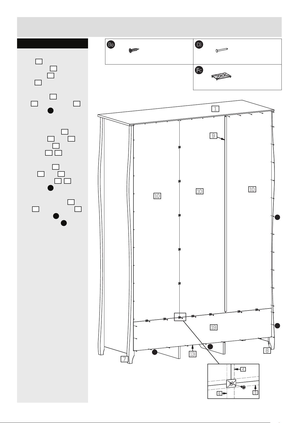
assembly instructions
step 1.20
place the remaining
10
back
on the top
h-prole
post
x the back 10 to the
top
using nails
place the back 19 onto
the posts
the bottom
back rails
x
posts
the back rails
using nails
nally x the backs
and
using screws
the back ttings
into the rabbet
1
, into the
9
, onto the
8
1
and the posts 8
Di
.
5
and 6,
5
and the
12/13
.
the back 19 to the
7
and 8 and
Di
12/13
.
10
19 to the bottom 5
Bo
through
Fc
.
Bo
ø3 x 12mm screw x
7
10
1.2 x 15mm nail xDi29
Fc
back fitting - 14 x 19mm x
1
9
10
7
10
Di
350807-15
19
Di
Di
13
7
4
6
5
Di
8
14
Page 16
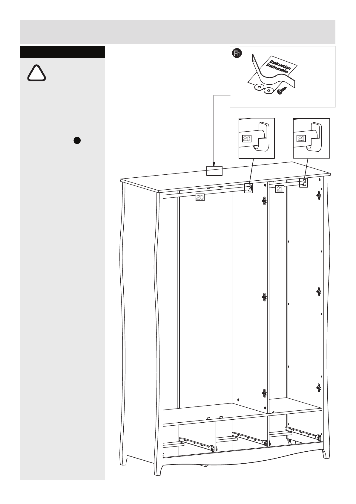
assembly instructions
step 1.21
important!
!
the wardrobe is
heavy. lift with care.
its recommended that
the wardrobe is xed to
the wall.
Fh
use the ttings
follow the instructions
included with the
ttings.
.
20
Fh
wall strap and instruction x 1
20
21
21
15
350807-16
Page 17
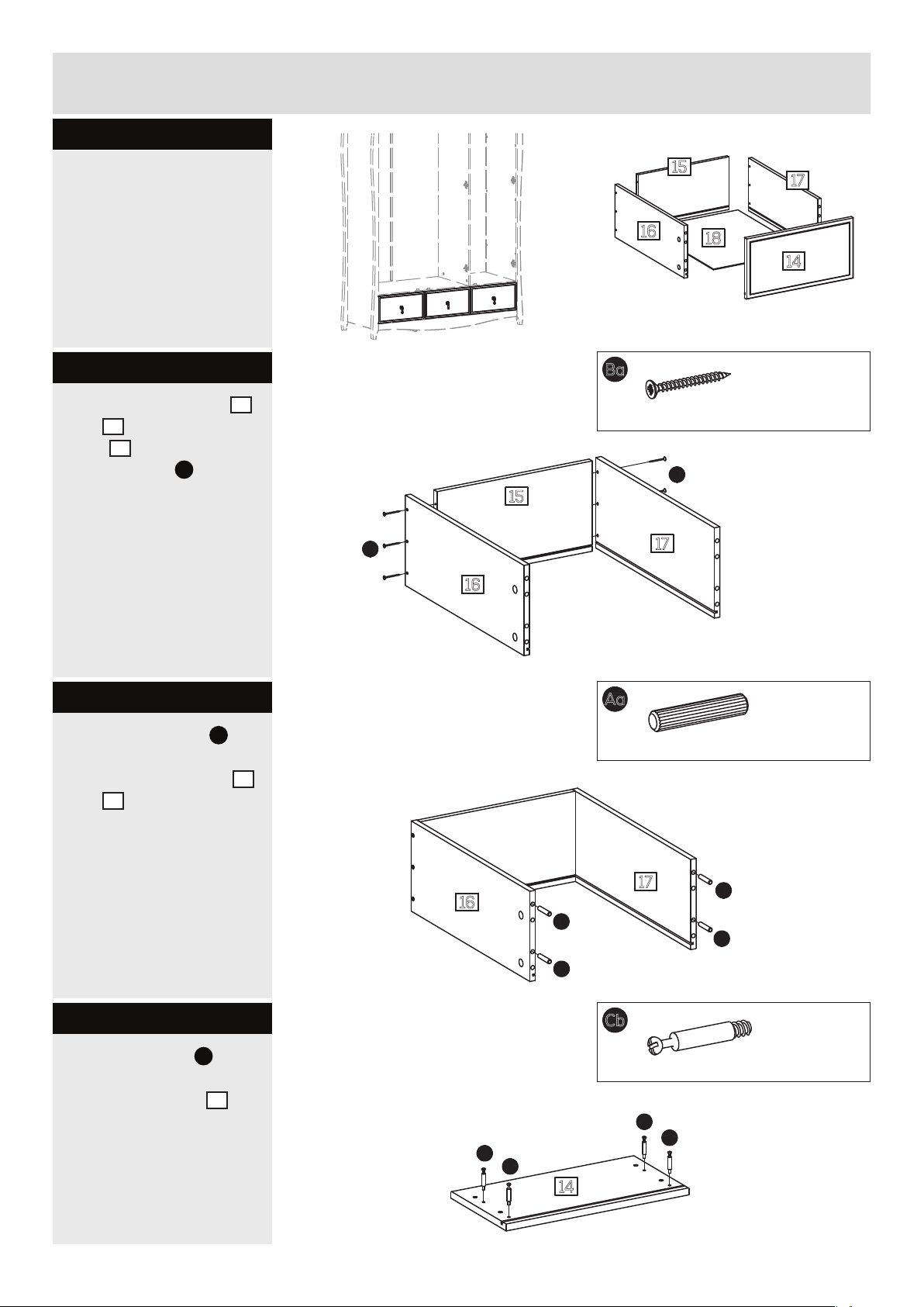
assembly instructions
step 2
assembly of the
drawers.
step 2.1
x the drawer sides
17
and
back
using screws
to the drawer
15
as shown,
Ba
.
16
15
17
16
18
14
x
3
ø3.5 x 35mm screw xBa18
Ba
15
Ba
17
16
step 2.2
knock the dowels Aa
into the holes indicated
on the drawer sides
17
and
using a smal
16
hammer.
step 2.3
screw the bolts Cb into
the holes indicated on
14
the drawer front
.
x
3
Aa
ø7.8 x 40mm wooden dowel x
12
17
Aa
16
Aa
Aa
Aa
x
3
Cb
ø5 x 8, cc34mm bolt x
Cb
Cb
Cb
Cb
12
14
350807-17
x
3
16
Page 18
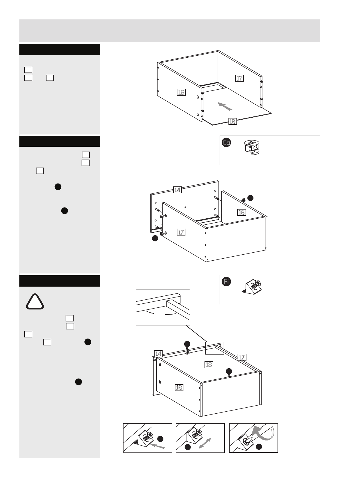
assembly instructions
step 2.4
slide the drawer bottom
18
into the drawer sides
16
and 17.
17
16
step 2.5
push the drawer front 14
onto the drawer sides
17.
and
place cams
holes indicated, arrow
pointing towards the front.
turn the cams
right to x the front.
Ca
into the
Ca
16
to the
step 2.6
18
x
3
Ca
ø15 x 10.5mm cam x
12
14
Ca
16
17
Ca
x
3
important!
make sure the
!
angle between
14
16
and
and
Fi
the drawer front
the drawer sides
17
is 90° before the drawer
18
bottom
as shown.
to adjust the angle between
the drawer sides and the
front push the tting
sidewards.
see details.
is xed using Fi
90°
14
Fi
16
back fitting w. ø3.5 x 15mm screw xFi6
Fi
17
18
Fi
x
3
Fi
Fi
17
350807-18
Page 19
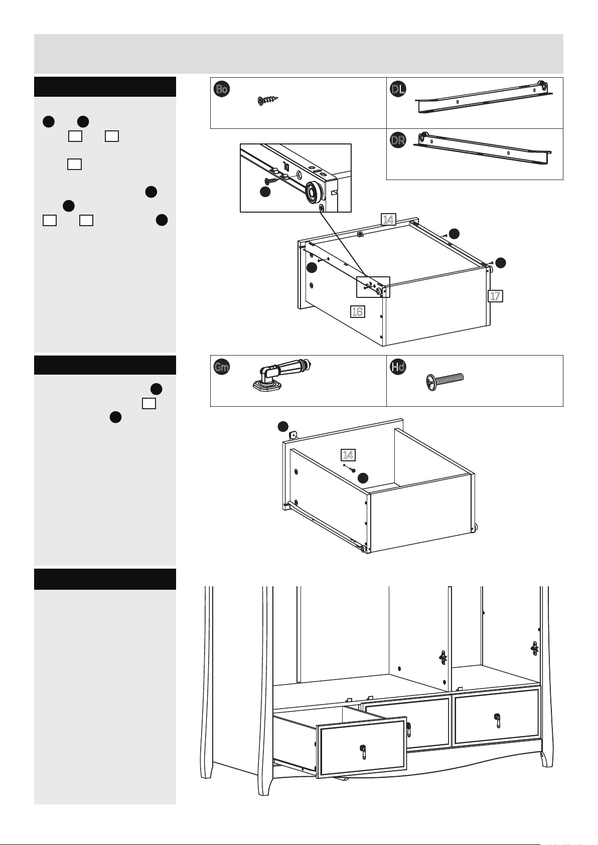
assembly instructions
step 2.7
place the drawer runners
DL
and DR onto the drawer
16
sides
and 17 and push
them onto the back of the
14
front
x the drawer runners
and
16
.
DL
DR
to the drawer sides
and 17 using screws Bo
into the holes indicated.
step 2.8
ø3 x 12mm screw xBo12
Bo
Bo
Gm
16
DL
450mm drawer runner, left x
DR
450mm drawer runner, right x
14
Bo
17
3
3
Bo
x the metal handles Gm
14
to the drawer front
Hd
using screws
.
step 2.9
slide the drawer onto
the runners and into the
wardrobe.
54mm handle x
Gm
3
m4 x 20mm screw xHd3
14
Hd
350807-19
18
Page 20
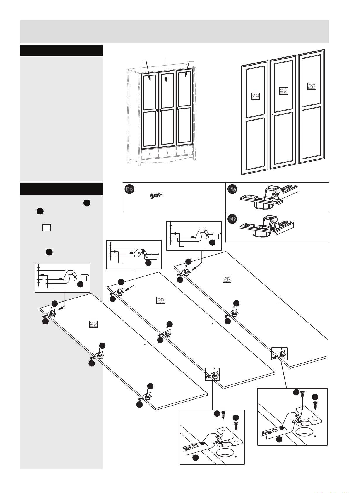
assembly instructions
step 3
assembly of the doors.
step 3.1
place the cup hinges Me
Mf
and
indicated on the
doors
x the hinges using
screws
into the holes
22
.
Bo
.
Door, center
Door, left
ø3 x 12mm screw xBo18
Small
Me
Door, right
22
22
22
Me
ø26mm cup hinge x
3
Mf
6
Large
Bo
ø26mm cup hinge x
Mf
Large
Bo
Mf
Me
Bo
Mf
22
22
Door, right
Bo
Door, center
Mf
22
Bo
Mf
Door, left
Mf
Bo
Mf
Bo
Me
Bo
Bo
Bo
Bo
Mf
19
Me
350807-20
Page 21
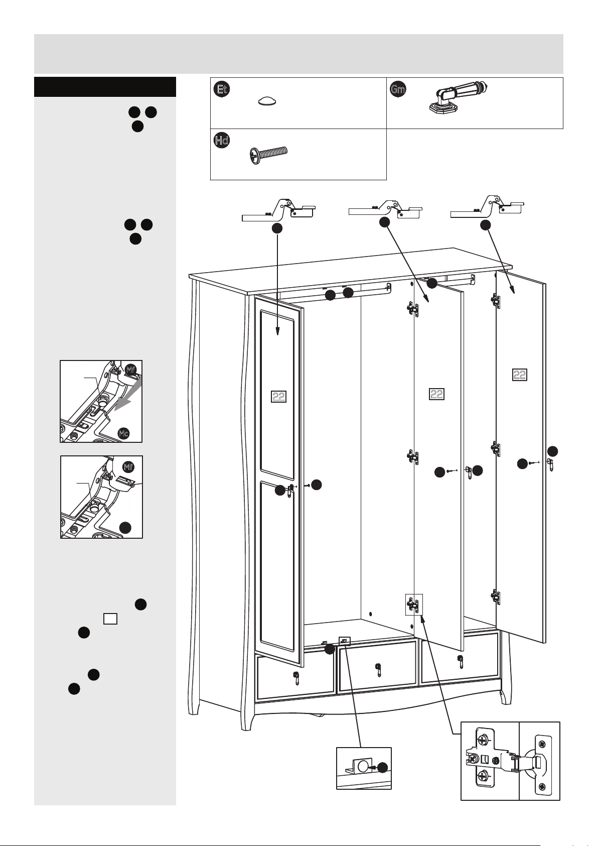
assembly instructions
step 3.2
slide the cup hinges
onto the crossplates
x the hinges using the
premounted screw in the
crossplates.
see details below on how
to t the cup hinge
onto the cross plate
Me/Mf
Mc.
Me/
Mc.
Mf
Mf
!
Gm
self adhesive bumper, ø10 x 3mm xEt6
54mm handle x
3
m4 x 20mm screw xHd3
Mf
Et
Et
Me
Et
Mf
22
22
22
Mc
Mf
!
Mc
x the metal knobs
to the doors 22
screws
Hd.
place the self adhesive
bumpers
stops
Et onto the door
Pm
.
Gm
using
Gm
Hd
Et
Gm
Hd
Gm
Hd
350807-21
Et
20
Page 22
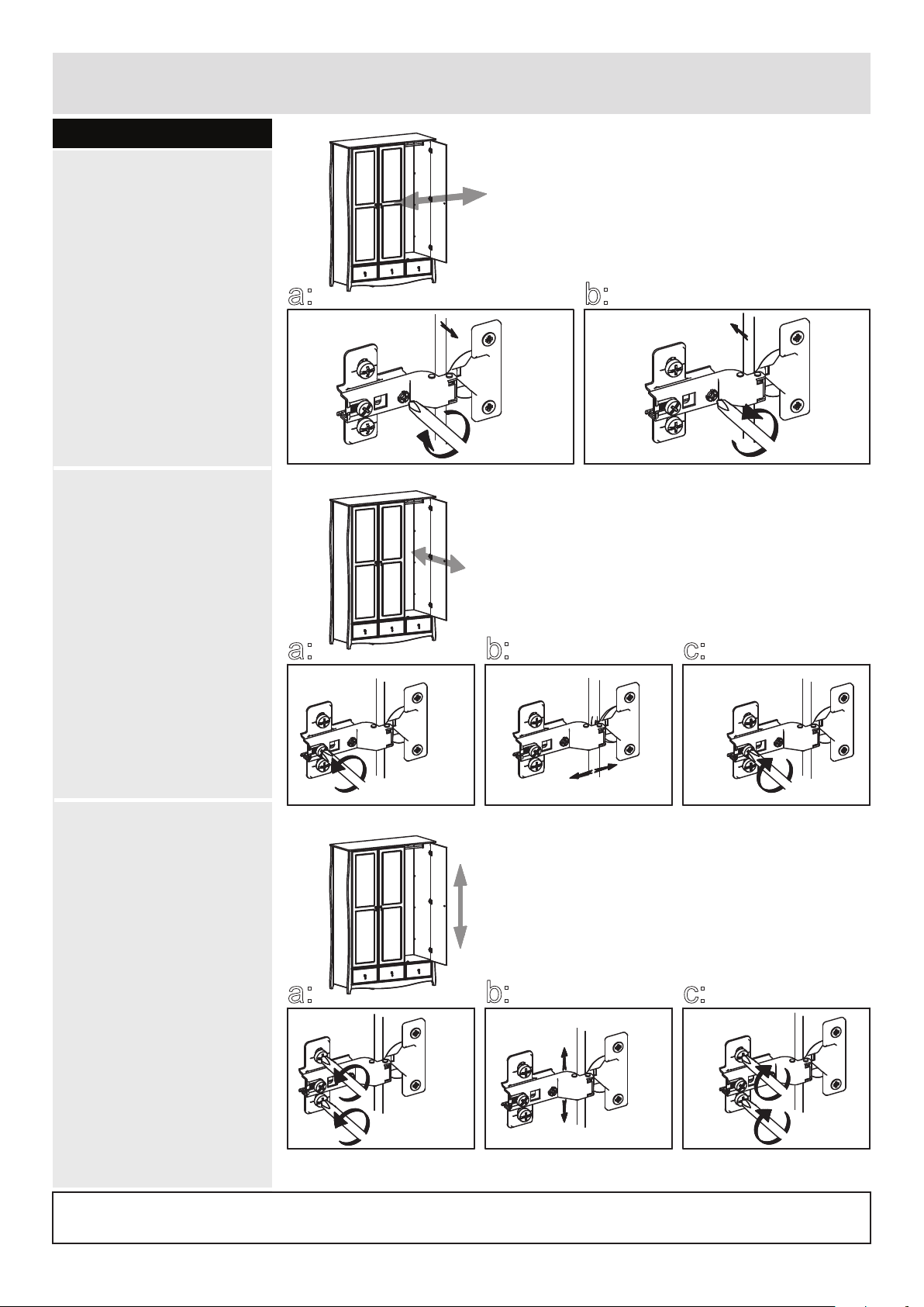
assembly instructions
step 3.3
adjusting the doors
left/right.
a:
to adjust the door
towards the left hand
side - turn the adjusting
screw to the right.
b:
to adjust the door
towards the right hand
side - turn the adjusting
screw to the left.
adjusting the doors
forwards/backwards.
a:
b:
a:
loosen the xing screw.
b:
push the cup hinges /
the door forwards or
backwards to adjust.
c:
tighten the xing screws
of all the crossplates.
adjusting the doors
up/down.
a:
loosen the two premounted screws of each
crossplate, but only as
much as it will allow the
cross plate to move up and
down.
a:
a:
b:
b:
c:
c:
b:
push the the door up or
down to adjust.
c:
tighten the pre-mounted
screws of all the
crossplates.
if you need help or have damaged or missing parts, call the argos customer helpline: 03456 400 800
home retail group - 489-499 avebury boulevard - saxon gate west - central milton keynes mk9 2nw
21
350807-22
Page 23
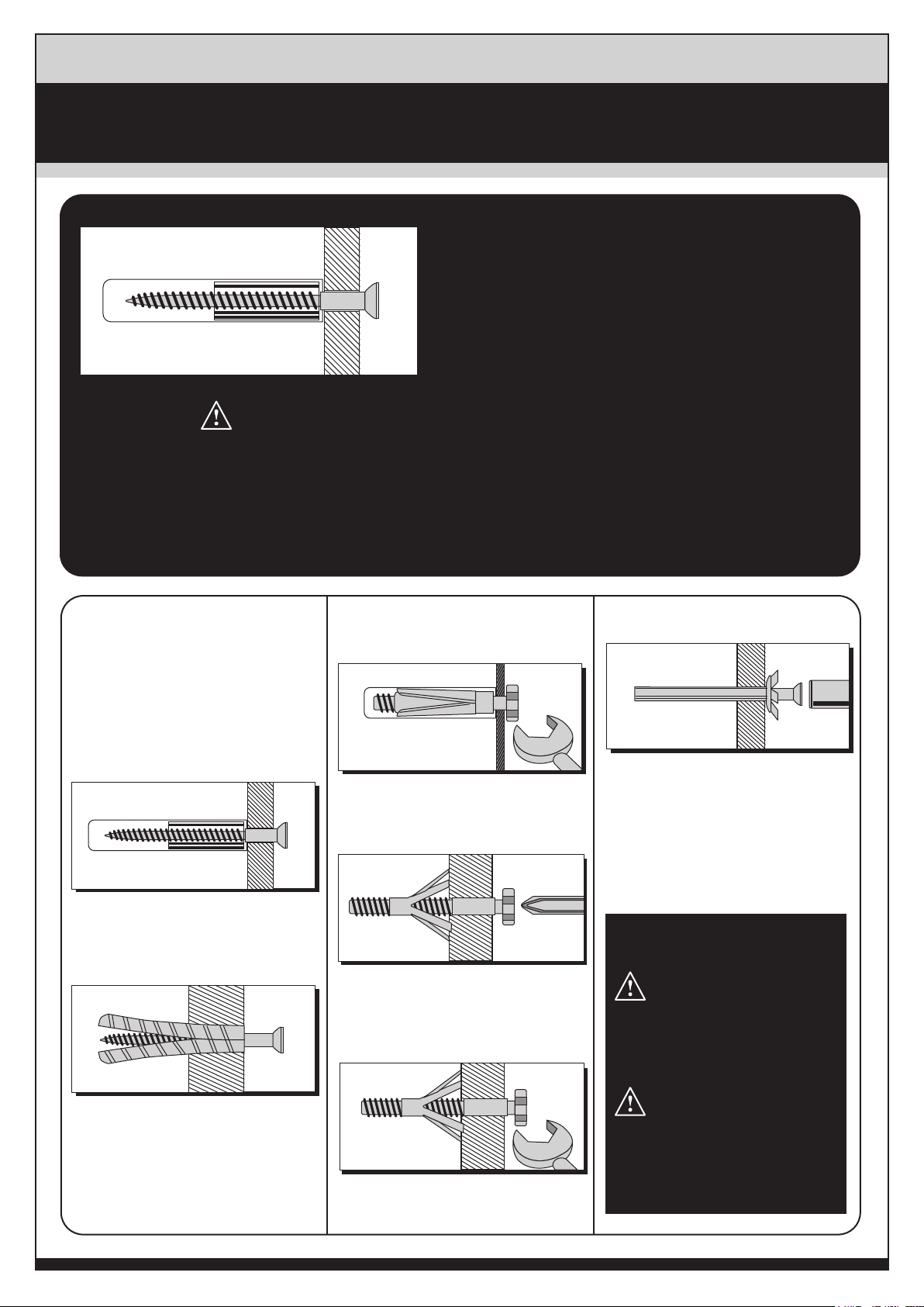
A Guide to
Wall Mounting & Fixings
IMPORTANT:
When drilling into walls always check that there are no
hidden wires or pipes etc. Make sure that the screws and
wall plugs being used are suitable for supporting your unit.
Consult a qualified tradesperson if you are unsure.
HINTS:
1) General Rule Always use a larger screw and wall plug if you are not sure.
2) Ensure you use the recommended drill bit to match the wall plug and hole size.
3) Ensure you drill the hole horizontally, do not force the drill or enlarge the hole.
4) Take extra care when drilling high walls, ceilings and ceramic tiles. Ensure the plug is fitting below the ceramic
tile to avoid splitting or cracking.
5) Ensure wall plugs are well fitted and are a tight fit in the drilled hole.
Types Of Walls
You can use one of the following types
of wall plug if your walls are made of
brick, breeze block, concrete, stone,
wood or plaster board.
No.1 "Standard" Wall Plug
General Wall Materials
These come in various sizes and are made
from plastic or sometimes wood fiber.
No.2 "General Purpose" Wall Plug
Aerated / Breeze Block
No.3 "Shield Anchor" Wall Plug
Heavy Loads
For use with heavier loads such as TV
& HiFi Speakers and Satellite Dishes etc.
No.4 "Cavity Fixing" Wall Plug
For use with plaster board partitions or
hollow wooden doors.
No.5 "Cavity Fixing - Heavy Duty"
Wall Plug
No.6 "Hammer Fixing" Wall Plug
For use with walls stuck with plaster
board. The hammer fixing allows it to
be fixed to the wall rather than the plaster
board. Always check the fixing is secure
to the retaining wall.
CARE & MAINTENANCE
SAFETY
Always check the fitting and
location to ensure your safety in
and around the home.
Generally aerated blocks should not be
used to support heavy loads, use a
specialist fitting in this case.
For light loads, a General Purpose Plug
can be used.
For use when fitting or supporting heavy
loads such as shelving, wall cabinets,
coat racks.
FITTING
From time to time check the fitting
to ensure the wall plugs or screws
do not become loose.
 Loading...