

Page 1
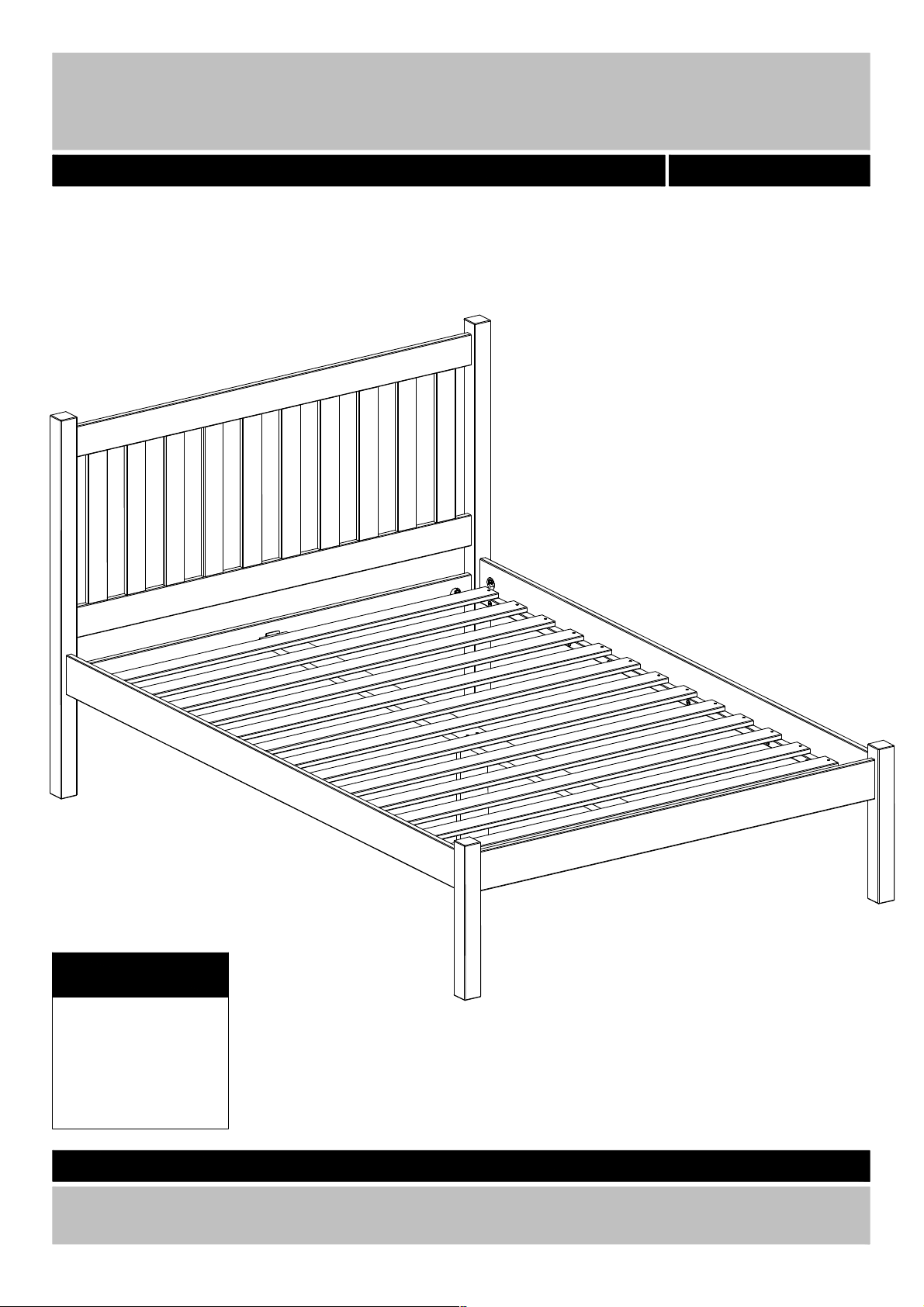
Silbury - bed 4,6"
Assembly Instructions - Please keep for future reference
39 22013
Dimensions
Width : 200,8
Depth : 142,3
Height : 110,0
Important - Please read these instructions fully before starting assem bly
If you need help or have damaged or missing parts, call the Customer Helpline:
36 8604 098
03456 400 800
Page 2

Safety and Care Advice
Important - Please read these instructions fully before starting assembly
• Check you have all the
components and tools listed on
pages 3 and 4.
• Remove all fittings from the
plastic bags and separate them
into their groups.
• Keep children and animals
away from the work area, small
parts could choke if swallowed.
• Make sure you have enough
space to layout the parts before
starting.
• Do not stand or put weight on
the product, this could cause
damage.
• Assemble the item as close to
its final position (in the same
room) as possible.
• Assemble on a soft level
surface to avoid damaging the
unit or your floor.
• Parts of the assembly will be
easier with 2 people.
• We do not recommend the use
of power drill/drivers for
inserting screws, as this could
damage the unit. Only use hand
screwdrivers.
• Dispose of all packaging
carefully and responsibly
Glue safety - Take care when using glue, please follow the advice below
Skin contact: Remove
contamination by washing with
soap and water. This procedure
should also be followed prior to
eating and drinking.
Eye contact: Rinse immediately
with clean water for 15 minutes
and seek medical advice.
If swallowed: Seek medical
advice immediately.
.
Care and maintenance
• Only clean using a damp cloth
and mild detergent, do not use
bleach or abrasive cleaners.
• From time to time check that
there are no loose screws on
this unit.
• This product should not be
discarded with household
waste. Take to your local
authority waste disposal centre.
Note: if required the next
page can be cut out and used
as reference throughout the
assembly. Keep this page with
these instructions for future
reference.
2
Page 3
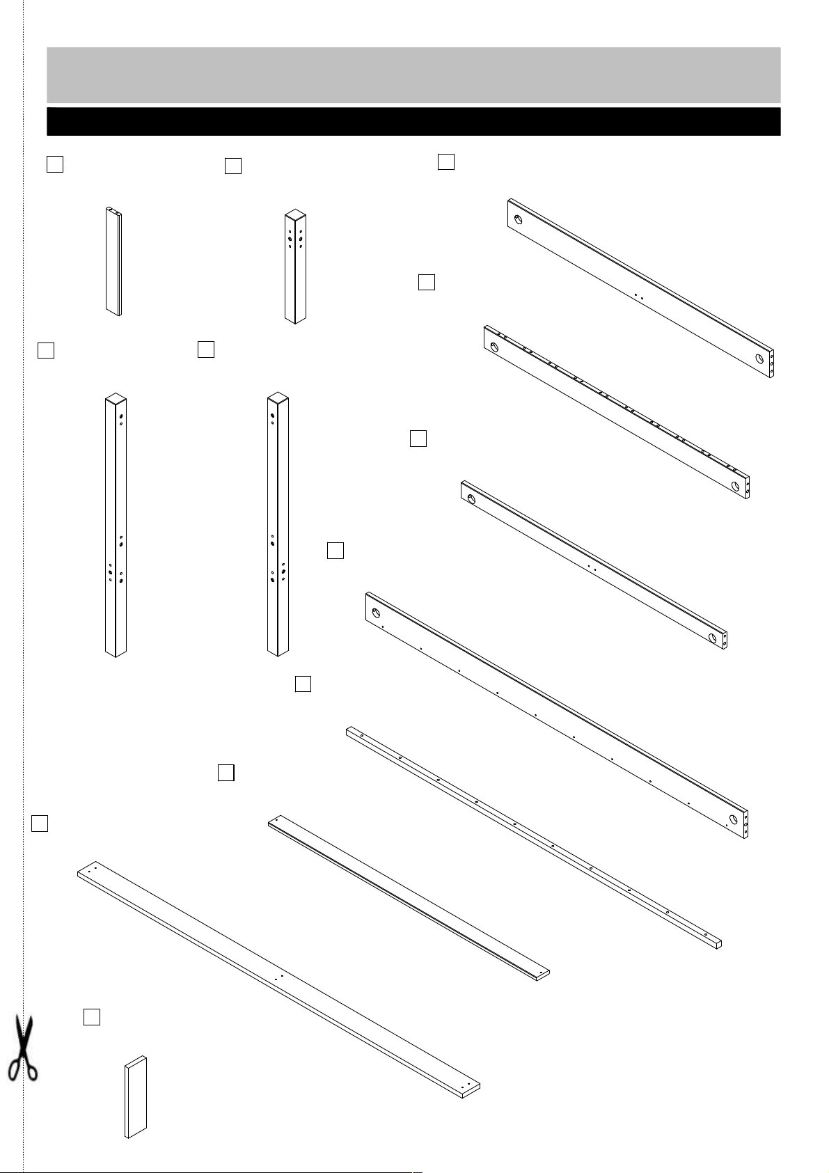
Components - Panels
Please check you have all the panels listed below
1
headboard upright x10
V160115
435x64x15 mm
headboard legs left
3
V540006
1100x54x54 mm
2
footboard legs x2
V540005
450x54x54 mm
headboard legs right
4
V540004
1100x54x54 mm
If you have damaged or missing components, call
the Argos Customer Helpline: 03456 400 800
footboard
5
V198111
1315x115x19 m m
headboard x2
6
V198105
1315x90x19 mm
7
headboard
P198115
1315x68x19 mm
center rail
11
P198101
1931x90x19 mm
10
slat x14
P160112
1348x65x15 mm
8
bed sid e x2
V198104
1900x115x19 mm
9
rail x2
P250014
1860x25x25 mm
12
center legs
P198102
304x90x19 mm
3
Page 4

If you have damaged or missing components, call
Components - Fittings
the Argos Customer Helpline: 03456 400 800
Please check you have all the panels listed below
Note: The quantities below are the correct amount to complete the assembly. In some cases more
fittings may be supplied than are required.
A B C
BA10369
ø8x40 mm wooden dowel x58
BA10696
M6xø10,5x20 m m screw bush x12
D E F
BA10659
M6x50 mm sector screw x12
BA10156
ø4,5x60 mm screw x2
BA10287
7x40 Ø15 screw x20
BA10070
ø3,5x30 mm x28
BA10821
45x40x29 m m bracket x2
J
BA103475
Ø35/40 cap x4
I10882
30 g glue x1
M N
BA10680
4 mm allen ke y x1
BA10678
6 m m allen key x1
BA10672
ø35 mm sector x12
BA10240
ø6,0x11,5 mm screw x8
IHG
LK
BA10663
120 mm sector key x1
Tools required
Ruler - Use this ruler to help correctly identify the screws
4
Page 5

Assembly Instructions
Step 1
Pour a drop of glue K
into the holes indicated
on the headboard
upright 1 before
knocking the dowels A
into the holes using a
small hammer.
Step 2
Knock the dowels A into
the holes indicated on
the headboard 6 and 7
using a small hammer.
K
A
A
1
K
x1
0
A
A
A
A
A
6
Step 3
Knock the dowels A into
the holes indicated on
the footboard 5 using a
small hammer.
7
A
A
A
A
A
5
5
A
A
Page 6

Assembly Instructions
Step 4
Insert the screw bush B
into the holes indicated
on the footboard legs 2
and the headboard legs
3 and 4 using the allen
key N.
x2
B
B
B
2
B
3
N
B
B
B
B
4
B
B
Step 5
Screw the sector screw D
into the holes indicated
on the footboard legs 2
and the headboard legs
3 and 4 using a flatblade
screwdriver.
Leaving at least 40 mm
remaining
. S ee details.
2
x2
D
D
D
3
D
D
D
6
D
D
D
D
4
D
Page 7

Assembly Instructions
Step 6
Push the footboard legs
2 onto the footboard 5.
2
5
2
Step 7
Insert the sector C into
the holes indicated on
the footboard 5 as
shown.
Fix the footboard legs 2
to the footboard 5 by
twisting the sector screw
D using the sector key L.
Tighten properly.
Fix the bracket I to the
footboard 5 usin g the
screw F.
C
L
2
F
5
F
C
2
i
7
Page 8

Assembly Instructions
Step 8
Pour a drop of glue K
into all the holes
indicated on the
headboard 6 before
placing the headboard
upright 1.
Push tightly together.
Step 9
Fix the 2nd headboard 6
by following the
instructions in step 8.
All 10 pieces in one step.
K
6
1
6
K
Step 10
Push the headboard legs
3 and 4 onto the
headboard 6 and 7 as
shown.
Ensure that the
headboards are faced
correctly.
3
7
6
4
8
Page 9

Assembly Instructions
Step 11
Insert the sector C into
the holes indicated on
the headboard 6 and 7
as shown.
(4 of them are located
on the opposite side)
Fix the headboard legs 3
and 4 to the headboard
6 and 7 by twisting the
sector screw D using til
sector key L.
Tighten properly.
Fix the bracket I to the
headboard 7 using the
screw F.
C
L
3
C
Step 12
Knock the dowel A into
the holes indicated on
the bed side 8 using a
small hammer.
Fix the rail 9 to the bed
side 8 using the screw E
and the allen key M
C
7
F
C
F
6
C
4
C
i
M
A
A
8
9
x1
0
E
9
x2
A
A
Page 10

Assembly Instructions
Step 13
Push the bed side 8 onto
the headboard and the
footboard as shown.
Ensure that both the
headboard and the
footboard a re fa ce d
correctly.
8
8
Step 14
Insert the sector C into
the holes indicated on
the bed side 8 as shown.
Fix the bed side 8 to the
footboard and the
headboard by twisting
the sector screw D using
the sector key L.
Tighten properly.
C
L
8
C
C
8
10
C
Page 11

Assembly Instructions
Step 15
Place the center rail 11
on the brackets I, fix it
to the brackets using
screw F
Place the center le gs 12
under the center rail 11,
fix it using screw G.
.
F F
12
G
G
11
F F
Step 16
Place the slats 10 onto
the rail 9.
Ensure there is
approximately the same
distance between the
slats.
Fix the slats using the
screw H.
9
H
x28
11
10
x14
Page 12

Assembly Instructions
Step 17
Place the cap J onto the
holes on the headboard
6.
J
J
J
J
Assembly is c omp lete.
If you need help or have damaged or missing parts, call the Customer Helpline:
Home Retail Group - 489-499 Avebury Boulevard - Saxon Gate West - Central Milton Keynes MK9 2NW
12
03456 400 800
 Loading...