

Page 1
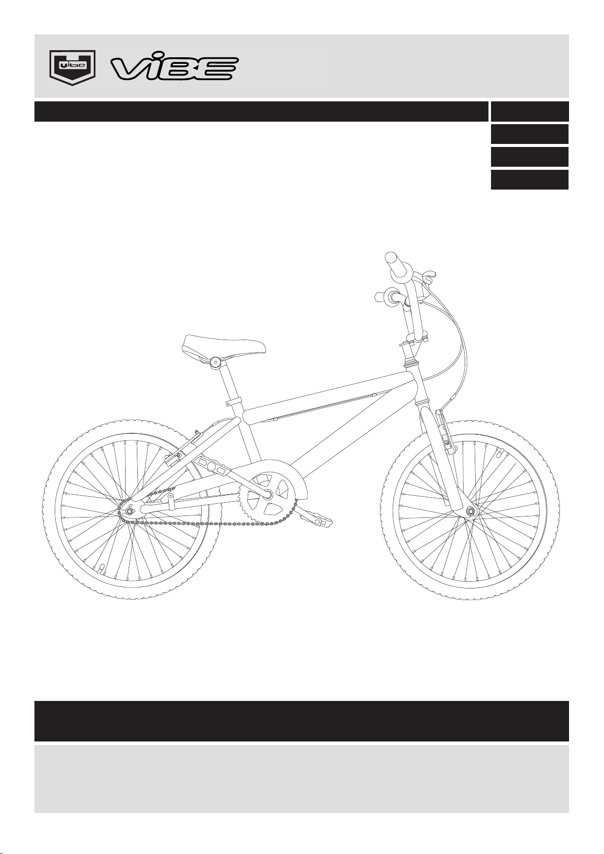
BMX BIKE
FREESTYLE / BMX BIKE
Maintenance Manual
402/9764
391/5116
411/4057
391/2061
Important – Please read these instructions fully before
rperforming any maintenance activities on the bike
These instructions contain important information that will help you get the best from
your bike,ensuring safe and correct maintenance.If you need help or have damaged
or missing parts, call the Customer Helpline : 0845 640 0800.
3
Aug 2011
Mar 2015
Page 2
Safety Information
Important – Please read these instructions fully
Customer Helpline 0845 640 0800
0345 640 0800
WARNING! This Bike has been designed, assembled and tested in accordance with the BS EN
14766:2005 standard to ensure your safety. To make sure the bike remains safe, it should only
be used for recreational use. Under no circumstances should it be used for competitive cycling,
stunting, jumping or acrobatic manoeuvres. These types of cycling may result in serious
personal injury and damage to the
WARNING!
size for your head and must conform to the European Standard EN1078:1997.
WARNING!
and use
WARNING! Always take extra care when riding in wet, foggy, windy or icy conditions. T
brakes may not be as effective and the braking distances may be increased.
WARNING! Always wear suitable cycling clothing when riding the bike. Loose clothing which
may get caught in moving parts should be avoided.
Always wear a cycle helmet when riding the bike. The helmet should be the correct
When riding in the dark, always make sure that the bike is fitted with suitable reflectors
a white front light and a red rear light.
bike.
he
WARNING! This bike is only suitable for use by riders (including any panniers and/or luggage)
with a weight of less than 115 kg (254 lb).
WARNING! The front and rear tyres must be
Under no circumstances should the tyres be inflated above the maximum pressure stated on
the side of the tyres.
WARNING! Only inflate the front and rear tyres of the bike using a bicycle pump. Do not attempt
to use another type of pump to inflate the tyres.
WARNING! As with all mechanical components, the bike is subjected to wear and high stres
Different materials and components may react to wear, stress or fatigue in different ways. If the
design life of a component has been exceeded, it may suddenly fail, possibly causing injuries to
the rider. Any form of crack, scratches or change of colouring in highly stressed areas indicate
that the life of the component has been reached and it should be replaced.
WARNING! Ensure only genuin
e replacement parts are used, especially for safety critical parts.
fully inflated before attempting to ride the bike.
ses.
CAUTION! Only use suitable tools to assemble the bike. The use of unsuitable tools may lead to
personal injury and damage to the bike.
2
Page 3
Safety Information
Important – Please read these instructions fully
CAUTION! The safety and smooth running of the bike can only be preserved with regular
maintenance. Always ensure the bike is maintained in accordance with the supplied maintenance
manual.
CAUTION! If the gears make a grinding sound while riding the bike. STOP immediately.
The bike may be unsafe and prolonged use may lead to personally injury or damage to the bike.
Inspect and, if required, repair the bike before using.
CAUTION! Do not clean your bike with pressure washers. These high pressure cleaning devices
may remove lubricant and/or grease from bearings and internal bike parts. This may lead to
poor performance.
CAUTION! When lubricating the moving parts of the bike, take care not to get any lubricant on
the rims of the wheels or the brake pads.
Customer Helpline 0845 640 0800
0345 640 0800
3
Page 4
Maintenance Instructions
Customer Helpline 0845 640 0800
0345 640 0800
Important – Please read these instructions fully
NOTE: It is recommended that your bicycle has a regular maintenance check every six months
carried out by a competent cycle mechanic to ensure that it is operating in perfect running order.
Frequent inspections should be carried out to ensure that all nuts, bolts and hardware are
secure and that no parts are worn or damaged.
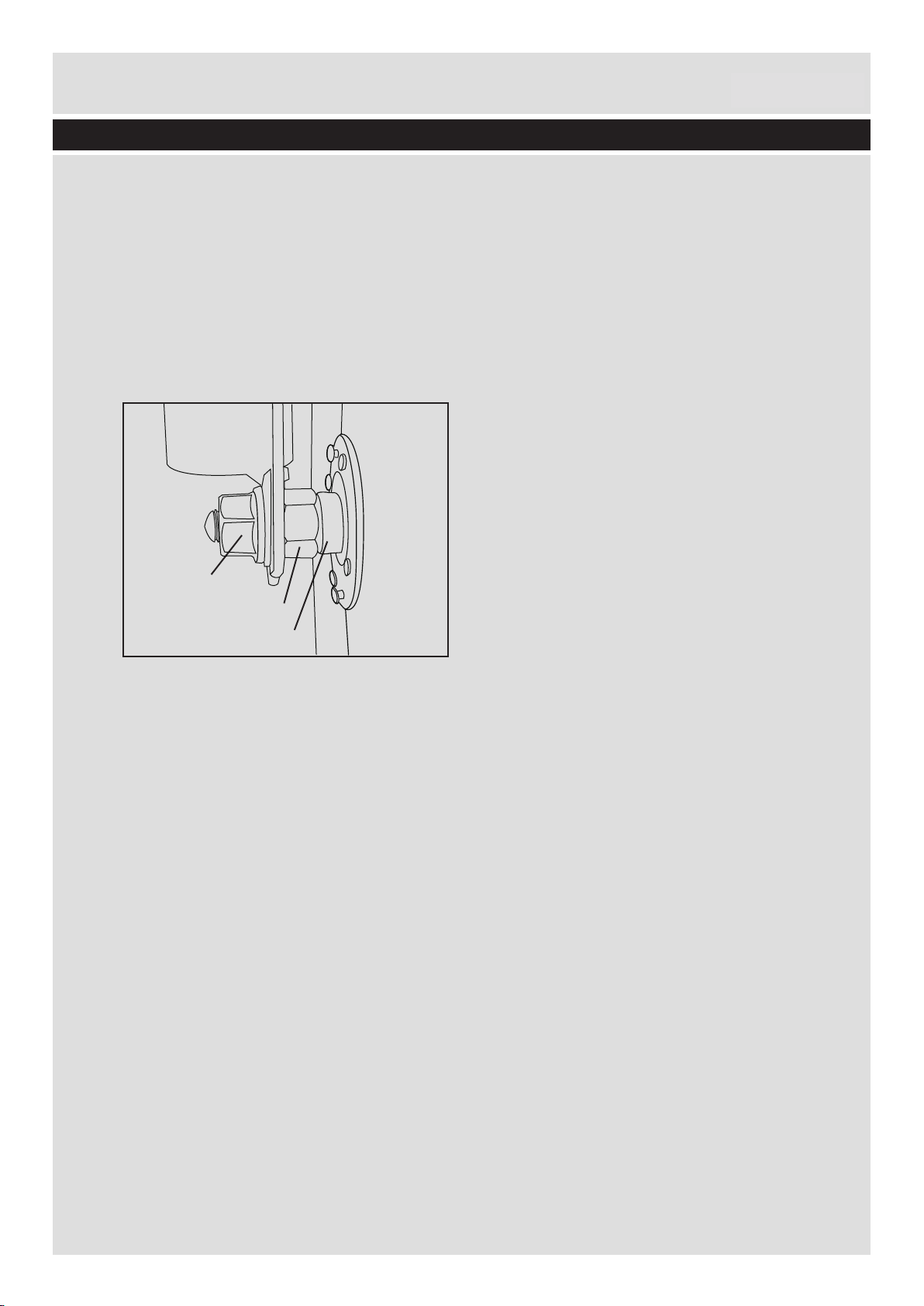
Bearing Adjustment: Th
are smooth and free from excessive play. If excessive side play occurs at the wheel rim, loosen
the axle nuts, loosen the cone lock nut “A” and adjust cone “B” with the multi-sized spanner.
Tighten lock nut “A” and tighten the axle nut.
e cones of all bearings should be periodically checked to ensure they
Axle Nut
A
B
Brake: Ensure that the brakes operate smoothly without locking or grabbing when applied. Make
periodic checks for wear and tear. Worn brake blocks and damaged brake cables MUST be
replaced immediately. For the best results use genuine replacement parts.
If on inspecting the brake blocks there is less than 3mm (1/8”) of rubber protruding from the
metal brake block holder then the brake block must be replaced.
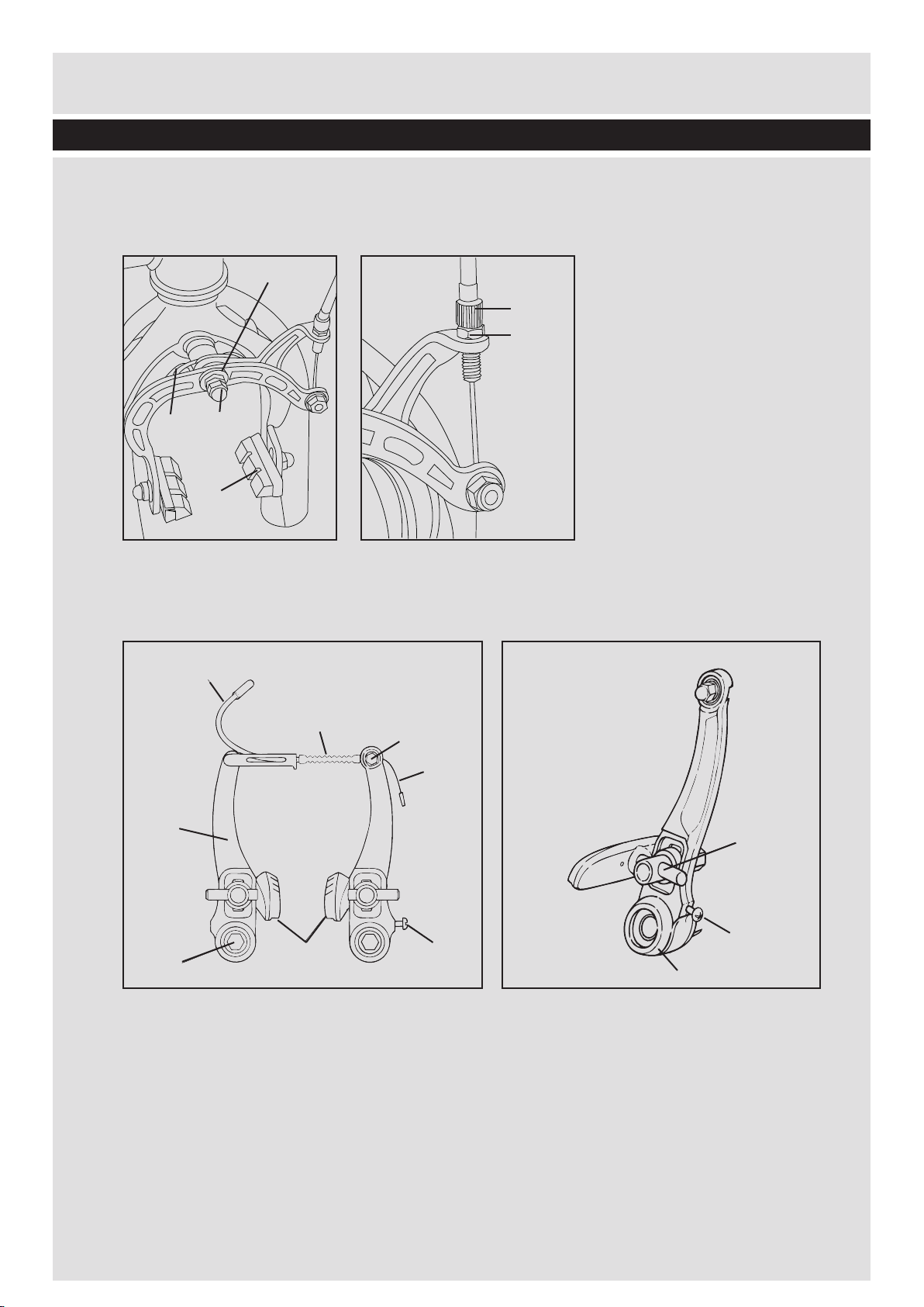
Calliper Brake: Brake callipers should function freely and release fully. If cal
recommend the following sequence of checks:
1. Make sure the brake lever and lever pivot operate smoothly. They should be clean and
lightly lubricated.
2. The inner brake cable must move freely within the outer brake cable. Inner brake cables
must be oiled or greased periodically.
3. Brake callipers should function freely. If the callipers are tight, adjustment of the brake
centre
pivot bolt may be required. Using 2 suitable 10mm spanners, hold the inner pivot nut
lipers bind we
(C) steady with one, and loosen the outer pivot nut (D) with the other. Carefully turn the
inner pivot nut anticlockwise (loosen) until the callipers do not bind BUT ARE NOT LOOSE.
Hold the inner nut (C) in this position and tighten the outer nut (D) so that both nuts are
locked together.
If the brake lever trave
bring the brake blocks closer to the wheel rim. When adjusted, lock nut (A) against the brake
arm.
4
l becomes excessive, loosen nut (A) and unscrew adjuster (B). This will
Page 5
Maintenance Instructions
Customer Helpline 0845 640 0800
0345 640 0800
Important – Please read these instructions fully
NOTE: Should one brake block (F) make contact with the wheel rim before the other, the brake
can be centralised. Using a hammer and a suitable punch, tap the return spring (E) on the
opposite side to the calliper/brake block that touches the rim first.
E
D
F
C
B
A
V Type Brakes
WARNING: V type brakes are powerful and sensitive. Until you are completely familiar with their
performance, use them with caution.
Fig A
1
6
8
7
Improper use may result in loss of control.
Fig B
2
3
4
5
1
2
3
Fig A
1. Guide Pipe (Noodle).
2. Rubber Boot
3. Pinch Bolt
4. Inner Cable
5. Adjusting Screw
6. Brake Arm
7. Brake Boss Bolt
8. Brake Blocks
Fig B
1. Brake Block Holder/Adjuster
2. Adjusting Screw
3. Spring
5
Page 6

Maintenance Instructions
Customer Helpline 0845 640 0800
0345 640 0800
Important – Please read these instructions fully
This type of brake offers powerful all round braking performance. They are not difficult to set up
and it is relatively easy to release the brake cable tension in order to remove or install a wheel
without deflating the tyre. To carry out this task, squeeze both brake arms together until the
brake blocks are firmly in contact with the wheel rim. Thi
and fore finger/index finger of one hand. Hold the guide pipe in the other hand and carefully pull it
until the conical end disengages from the pivoted cage. Raise the guide pipe and cable until the
brake inner cable clears the cage. Release both brake arms. To connect the brake, reverse this
procedure.
The height and angle of each brake block can be adjusted
nut with a 10mm spanner. To obtain good braking performance, the length of the inner brake
cable between the pivoted cage and brake arm i.e. the part of the cable covered by the rubber
boot, should be approximately 40mm. Carefully loosen one brake block and hold it against the
wheel rim. Using a 5mm hexagonal / Allen key inserted in the front of the brake block
s can be accomplished with the thumb
by loosening the brake block holder
holder to
maintain this position, securely tighten the 10mm retaining nut at the rear of the brake.
Repeat this procedure with the opposite brake block making sure that each brake block is the
same distance from the holder, each block is the same height and each block is parallel to the
wheel rim.
On squeezing the brake lever, both brake arms should operate simultaneously and the brake
blocks sh
and rim should be between �mm-�mm. When viewed from the front, the left hand brake arm and
brake block assembly should be a mirror image of the right hand side.
Either one or both arms may be fitted with a small adjusting screw near their pivoted end. This
screw adjusts the return spring tension and by turning it
anticlockwise (less tension) it should be possible to balance each brake arm so they operate
together.
IMPORTANT: For your own safety, make sure both brakes work efficiently before each ride.
Check the security of all nuts, bolts and fixings and replace worn or damaged brake blocks and
cables.
Chain: The chain should have approximately 10mm (3/8”) of vertical movement
ould make good contact with the wheel rim. The clearance between each brake block
clockwise (more tension) or
when checked
in the centre between the front and rear sprockets. To adjust the chain tension, slightly loosen
the rear axle nuts and either pull the rear wheel backwards if the chain is too loose, or push it
forwards if the chain is too tight. Before securely re-tightening the rear axle nuts make sure that
the chain is correctly tensioned and the rear wheel runs centrally. Oil your chain sparingl
month by revolving the pedal cranks and apply to each link. Wipe away excess oil with a dry
cloth.
6
y once a
Page 7
Maintenance Instructions
Customer Helpline 0845 640 0800
0345 640 0800
Important – Please read these instructions fully
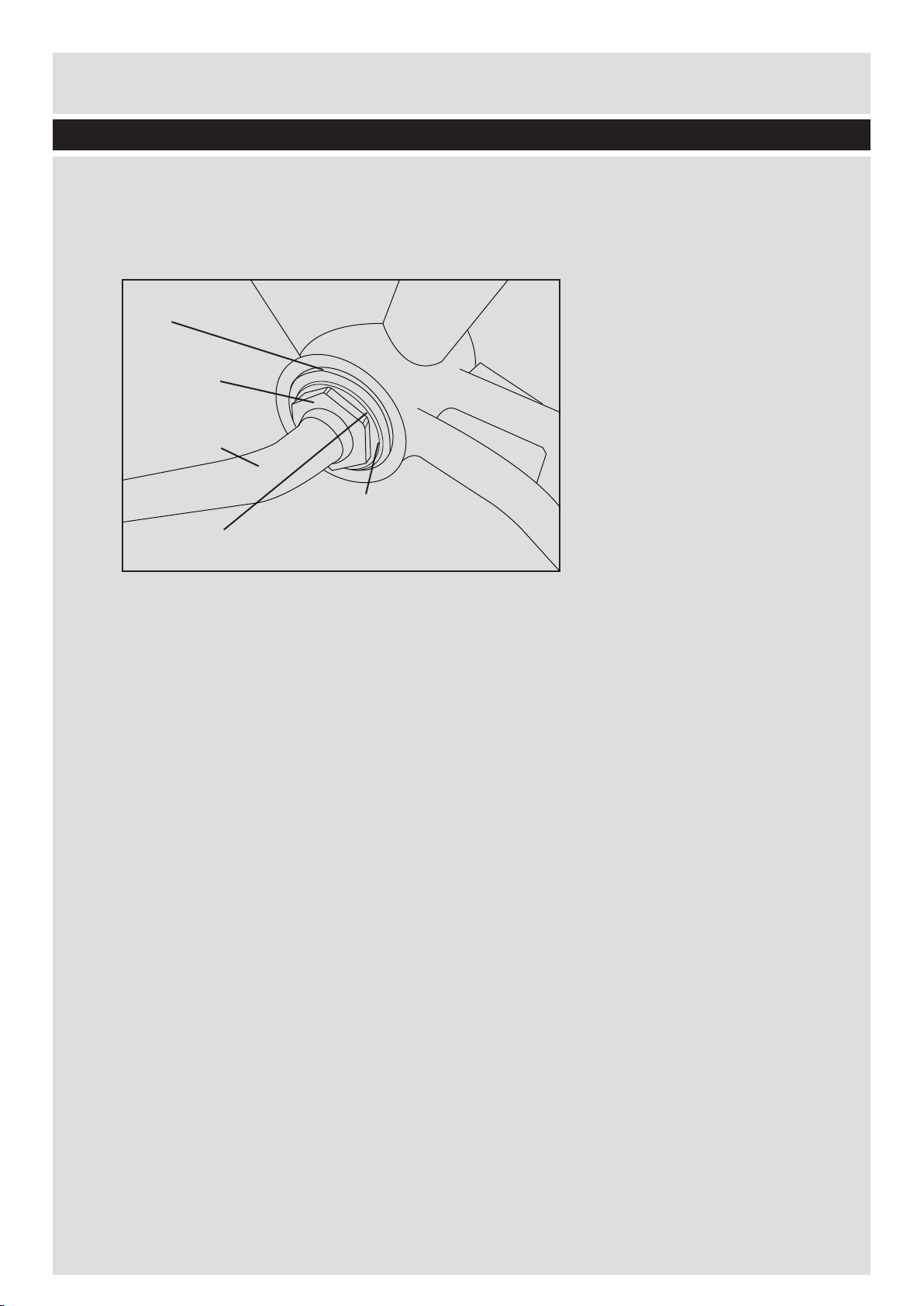
Bottom Bracket Adjustment (1 piece)
A correctly adjusted one piece crank should rotate freely and have no side play. To check for
play, hold both the left and right crank arms and try to move them in a rocking motion (pull/push).
If excessive play is felt then the crank must be adjusted.
Slot
Lock Nut
Crank Arm
Lock Washer
Adjustable Cone
Tools: The tools required to adjust a one piece crank are: an adjustable spanner with a jaw width
of up to 32mm, a small hammer/mallet and an old flat headed screwdriver.
Adjustment:
Note – the lock nut and adjustable cone BOTH have a left hand thread i.e. They undo in a
clockwise direction.
Using the adjustable spanner, loosen the lock nut and rotate this by 1 or 2 turns. Prise the slotted
lock
washer away from the adjustable cone to ensure good access to the adjustment slots.
Locate the head of the screwdriver into the slot and carefully tap the end with a mallet/hammer to
rotate the cone.
Excessive play? Cone must be tightened. Turn anti-clockwise.
Cranks too tight? Cone must be loosened. Turn clockwise.
Whilst carrying out this adjustment, frequently check the bearings for play/f
correct, move the lock washer against the cone and tighten the lock nut. Turn anti-clockwise.
Ensure the lock nut is firmly secured. If you have any doubt about the adjustment of the bottom
ree rotation and when
bracket bearings, ask a competent cycle mechanic to make the adjustment.
Cleaning: Your bicycle should be cleaned with warm soapy water (except the chain). Rinse with
clean water and d
On paintwork use a good wax polish.
Handlebars: Adjust for comfort and a proper fit. Make sure that the handlebar stem is inserted to
at least its Minimum Insertion mark. Securely fasten the handlebar bolt and nut/expander bolt.
Replace any worn grips.
Lubrication: To ensure that the bicycle remains in good working
lubricated regularly.
ry with a soft clean cloth, afterwards oil the bicycle in the appropriate areas.
order, moving parts should be
7
Page 8

Maintenance Instructions
Customer Helpline 0845 640 0800
0345 640 0800
Important – Please read these instructions fully
The front hub, rear hub and headset are greased prior to leaving the factory. Correct further
lubrication requires disassembly, cleaning and re-packing and should be done by a qualified
bicycle mechanic.
Using a light machine type oil periodically lubricate the chain, rear wheel sprocket, brake lever
pivots, brake inner cables and the calliper brak
on the type of brakes fitted).
To avoid over lubricating, do not oil where lubricant is still evident from the previous maintenance.
Should you accidentally over lubricate, wipe clean any excess.
WARNING: Should any oil come into contact with the wheel rim or brake blocks, this should be
wiped off and the components cleaned with a de-greasing agen
NOTE: When storing your bicycle for prolonged periods, smear any chrome plating with light
grease.
Punctures: Inner tube punctures can be caused by riding over sharp stones, holes in the road or
e centre bolt or V brake pivot points (depending
t.
by hitting curb stones.
In the event of a puncture the tyre should be completely removed. With the inner tube deflated,
push the tyre to the centre of the rim. Carefully hook a tyre lever (not suppl
under the edge of the tyre and gently lever the tyre bead over the edge of the rim. Repeat this
procedure with a second tyre lever positioned a few inches away from the first one. It should now
be possible to pull the complete side of the tyre off. Push the valve back through the rim and
remove the inner tube. Finally, remove the tyre.
Carefully check the inside of the tyre
nails/ pins/ thorns etc. These must be removed.
Repair the inner tube using a puncture repair kit – follow the instructions supplied.
To replace the tyre, fit one side of the tyre back onto the rim. Push the valve through the rim
valve hole and feed the inner tube into the tyre. Make sure the inner tube is slightly inflated and
then ‘work’
Slowly inflate the tyre making sure it is sitting squarely and is sealed correctly on the rim. When
fully inflated replace the valve cap.
Saddle: Adjust for comfort and proper fit. Never allow the ‘minimum insertion’ mark to show
above the top of the seat tube.
Steering: The steering of your bicycle should be smooth and easy.
Tyres: To obtain the
the tyre back on to the rim using both thumbs.
maximum life and full benefit from pneumatic tyres, ensure they are inflated
for sharp objects that may have caused the puncture i.e.
ied with the bicycle)
according to the pressure indicated on the tyre sidewall. Your tyres should be inflated
slowly, using a manual foot or hand pump fitted with a “Schrader” valve connector and pressure
gauge.
8
Page 9
Torque
Torque
Description
Nm
Ibf.in
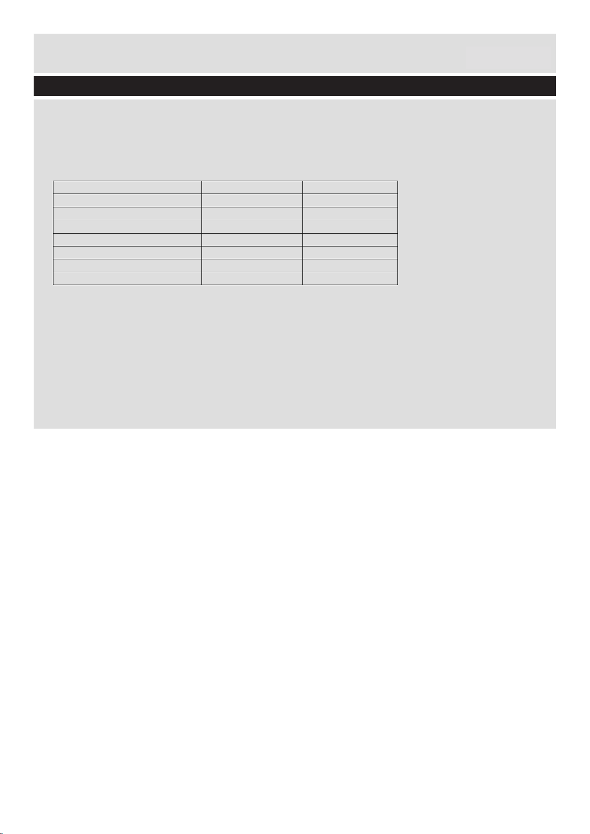
Front Wheel Nut
22-25
195-220
Rear Wheel Nut
25-29
220-225
Handlebar Expander Bolt
15-17
130-150
Handlebar Clamp Bolt
16-18
140-160
Saddle Clamp
16-18
140-160
Seat Post Bolt
16-18
140-160
Maintenance Instructions
Customer Helpline 0845 640 0800
0345 640 0800
Important – Please read these instructions fully
Pressurised pumps should not be used.
Ensure the tyre is properly positioned onto the wheel rim as incorrect alignment can cause
chafing of the tyre against the frame or fork tubes. Make sure that when purchasing replacement
tyres you obtain the correct size. The tyre size is found on the tyre sidewall.
Torque Settings: Recommended Torque settings
Replacement Parts / Spares
Moving parts on your bicycle are subject to wear and tear. Brake blocks, tyres, stabilisers and
bearings may need replacing due to prolonged use and other components such as inner tubes
and handlebar grips sometimes get damaged in service.
If any part of the bicycle has to be replaced make sure the replacement is of the correct type and
size – if you are in any doubt,
ask a competent cycle mechanic.
for cycle components:
9
 Loading...