

Page 1
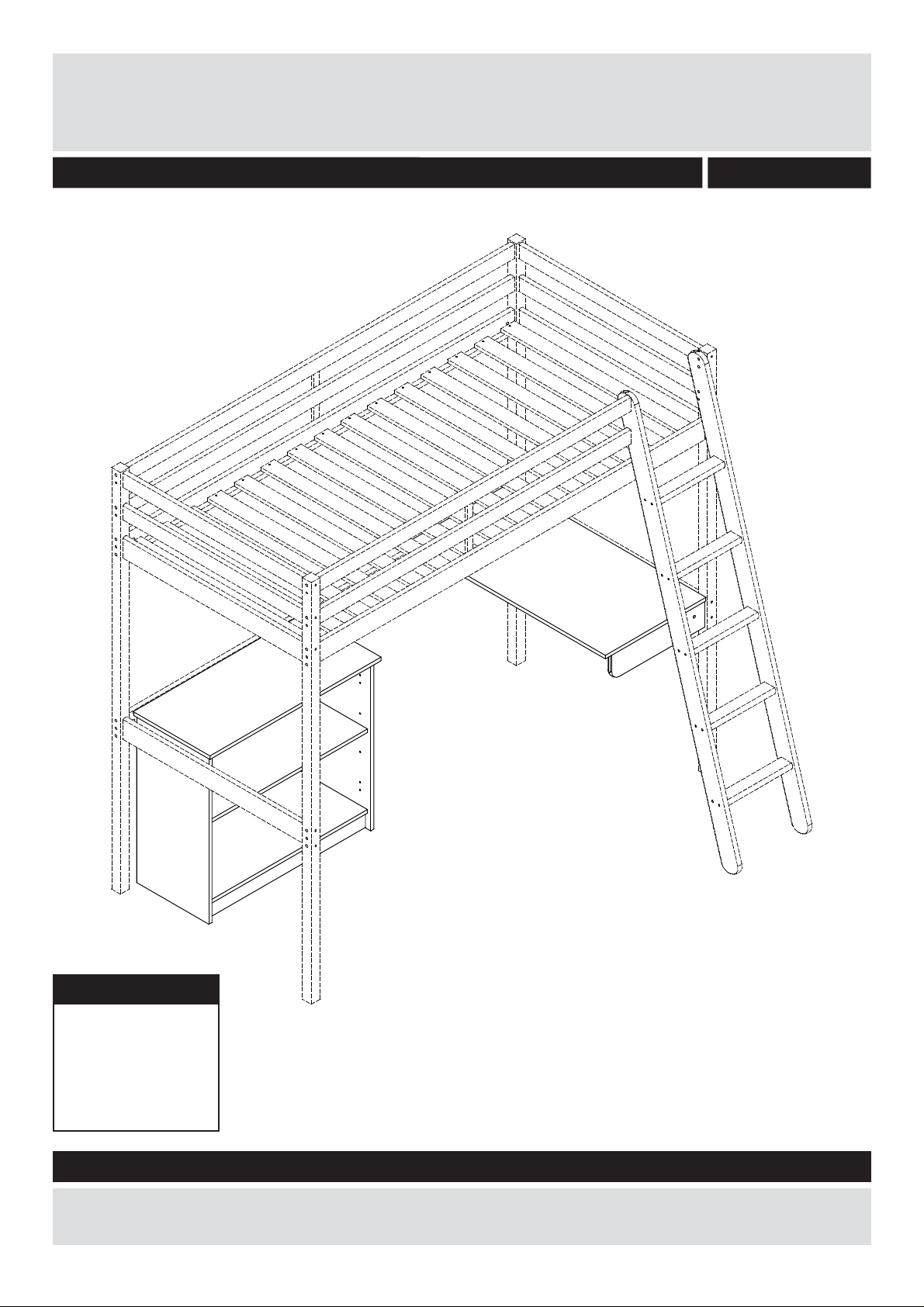
Shelf unit + Desk
Assembly Instructions - Please keep for future reference
1589317
Dimensions
Length - 83/95cm
Depth - 37/49cm
Height - 73/13cm
Weight - 20kg
Important – Please read these instructions fully before starting assembly
If you need help or have damaged or missing parts, call the Customer Helpline:
0045 7668 8055 or e-mail: order@fl exa.dk
Issue 1 - 15/05/14
Page 2
Safety and Care Advice
Important – Please read these instructions fully before starting assembly
• Check you have all the
components and tools listed on
pages 2 and 3.
• Remove all fi ttings from the
plastic bags and separate them
into their groups.
• Keep children and animals
away from the work area, small
parts could choke if swallowed.
• Make sure you have enough
space to layout the parts before
starting.
Care and maintenance
• Only clean using a damp cloth
and mild detergent, do no use
bleach or abrasive cleaners.
• Do not stand or put weight on
the product, this could cause
damage.
• Assemble the item as close
to its fi nal position (in the same
room) as possible.
• Assemble on a soft level
surface to avoid damaging the
unit or your fl oor.
• Parts of the assembly will be
easier with 2 people.
• From time to time check that
there are no loose screws on
this unit.
• We do not
recommend the
use of power
drill/drivers for
inserting screws,
as this could
damage the unit. Only use hand
screwdrivers.
• Dispose of all packaging
carefully and responsibly.
• This product should not be
discarded with household waste.
Take to your local authority
waste disposal centre.
Note: if required the next
page can be cut out and used
as reference throughout the
assembly. Keep this page with
these instructions for future
reference.
1
Page 3
If you have damaged or missing components,
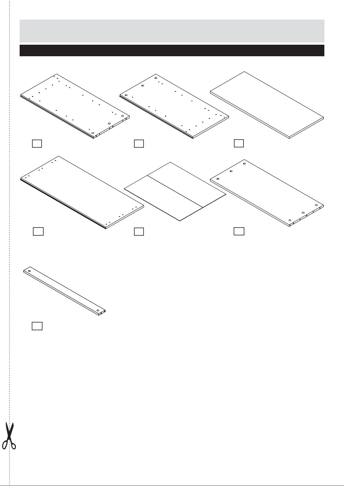
Components - Parts
call the Customer Helpline: 0045 7668 8055
Please check you have all the parts listed below
Side panel Left x1
1
(70.6x35x1.5cm)
No. 15-01507062-20
Top x1 (82.5x37x1.5cm)
4
No. 15-01508252-20
Side panel Right x1
2
(70.6x35x1.5cm)
No. 15-01507061-20
Back panel x1
5
(78.2x64.8/32.4x0.3cm)
No. 4309-0307821
Shelf x1
3
(76.5x33.1x1.5cm)
No. 15-01507651-20
Base x1 (76.5x33.1x1.5cm)
6
No. 15-01507652-20
Plinth x1 (76.5x6.5x1.5cm)
7
No. 12-01507651-20
2
Page 4
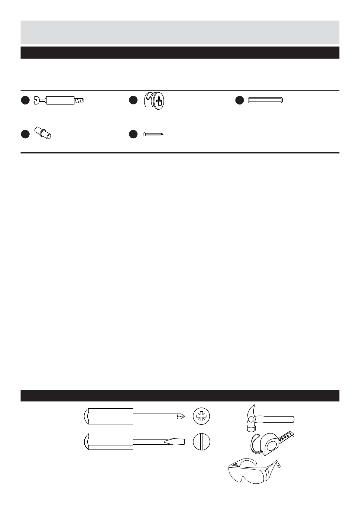
Components - Fittings
Please check you have all the fi ttings listed below
Note: The quantities below are the correct amount to complete the assembly. In some cases more fi ttings
may be supplied than are required.
No. 4020-005
A
7x34mm for ø5 Minifi x bolt x14
No. 4013-003
D
ø5x16mm Shelf support x4
No. 3933-15010
B
ø15x9.5mm Minifi x cam x14
No. 4022-006
E
1.2x20mm Nail square x25
No. 3930-05030
C
5x30 mm Dowel x14
Tools required
Phillips
screwdriver
(medium)
Flatblade
screwdriver
(medium)
3
Small
hammer
Ruler/tape
measure
Eye protection
(when using a
hammer or glue)
Page 5

Assembly Instructions
Step 1
Attach the dowels C to
7
plinth
panels
It may be necessary
to tap the dowels in
very gently with a small
hammer.
Attach minifi x bolts
side panels
, base 6, side
1
and 2.
A
1
and 2.
to
C
C
7
6
C
C
Step 2
Attach side panels
2
and
and plinth
minifi x cams
to the base 6
7
with the
B
.
1
C
A
A
B
1
1
B
6
2
A
2
B
B
7
B
4
Page 6

Assembly Instructions
Step 3
Attach minifi x bolts A to
4
top
.
A
A
A
4
Step 4
4
Attach top
panels
the minifi x cams
to side
1
and 2 with
B
4
B
.
B
2
B
1
6
5
Page 7

Assembly Instructions
Step 5
Attach the back panel
5
with nails E to the
back side of the shelf and
E
carefully tap the nails
in the circumferance.
E
E
5
Step 6
Position the shelf
D
supports
holes in the side panels
1
and 2. Shelf
supports should be at the
same level.
Place shelf
shelf supports
Assembly of this
furniture is fi nished.
into the
3
onto the
D
.
D
2
3
1
D
6
Page 8

If you have damaged or missing components,
Components - Parts
call the Customer Helpline: 0045 7668 8055
Please check you have all the parts listed below
Table top x1
8
(95.0x48.5x1.5cm)
No. 15-01509501-20
Support arm x1
9
(45.0x11.5x1.8cm)
No. 12-01804501-20
7
Page 9

Components - Fittings
Please check you have all the fi ttings listed below
Note: The quantities below are the correct amount to complete the assembly. In some cases more fi ttings
may be supplied than are required.
No. 3913-061001
G
M6x100mm Connecting bolt x1
No. 3930-10045
i
10x45 mm Dowel x2
No. 3922-06018
H
ø10x18mm Barrel nut x1
No. 3901-35016
J
3.5x16mm Chipboard screw x24
No. 4008-019
F
50x50x15x2mm Angle x6
Tools required
Phillips
screwdriver
(medium)
Flatblade
screwdriver
(medium)
Allen key
4mm incl.
No. 4033-004
Small
hammer
Ruler/tape
measure
Eye protection
(when using a
hammer or glue)
8
Page 10

Assembly Instructions
Step 7
Attach the dowels i to
9
the support arm
.
It may be necessary
to tap the dowels in
very gently with a small
hammer.
i
9
Step 8
H
Put the barrel nut
the support arm
Attach the support arm
9
to the bed leg with the
connecting bolt
to
9
.
G
.
G
H
9
H
G
9
H
G
9
Page 11

Assembly Instructions
Step 9
Place the table top 8 on
the bed side (1.) and the
9
support arm
Attach table top
.
8
to
the bed side (1.), to the
endrail (2.) and to the
9
support arm
angles
screws
F
J
with
and chipboard
.
(1.)
J
F
9
8
(2.)
Assembly is complete.
F
J
If you need help or have damaged or missing parts,
E-mail: order@fl exa.dk
8
J
F
J
(1.)
J
(2.)
call the Customer Helpline: 0045 7668 8055
Ref.no. 44-01360-20 A Stand: 120614 Page 11 (81-08707-20)
10
 Loading...