

Page 1
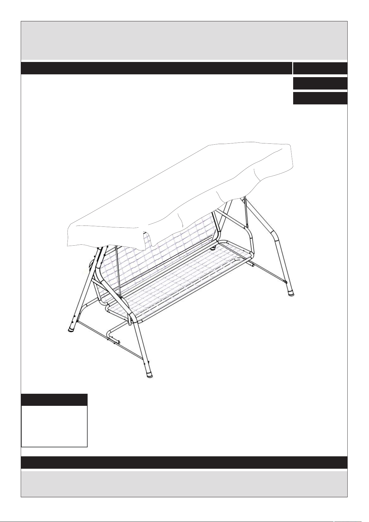
2 SEATER SWING HAMMOCK
Assembly Instructions - Please keep for future referenc e
450/4272
Dimensions
Width - 151 cm
Depth - 113 cm
Height - 154 cm
Important – Please read these instructions fully before starting assembly
If you need help or have damaged or missing parts, call the Customer Helpline:
Argos = 0345 6400800
ISTR.675 - 09/12/15
Page 2

Safety and Care Advice
Important – Please read these instructions fully before starting assembly
• Check you have all the
components and tools listed on
the following pages.
• Remove all fittings from the
plastic bags and separate them
into their groups.
• Keep children and animals
away from the work area, small
parts could choke if swallowed.
• Make sure you have enough
space to layout the parts before
starting.
• During assembly do not stand
or put weight on the product,
this could cause damage.
• Assemble the item as close
to its fi nal position (in the same
room) as possible.
• Assemble on a soft level
surface to avoid damaging the
unit or your floor.
• Parts of the assembly will be
easier with 2 people.
• To reduce
the likelihood of
damaging your
product please
ensure that your
power drill is set on a low torque
setting.
Care and maintenance
• Only clean using a damp cloth
and mild detergent, do no use
bleach or abrasive cleaners.
Handy Hints
• Assemble all parts and bolts
loosely during assembly, only
once the product is complete
should you fully tighten the bolts
• From time to time check that
there are no loose screws on
this unit.
• Regularly check and ensure
that all bolts and fittings are
tightend properly.
• This product should not be
discarded with household waste.
Ta ke to your local authority
waste disposal centre.
Note: if required the next
page can be cut out and used
as reference throughout the
assembly. Keep this page with
these instructions for future
reference.
1
Page 3

Components - Panels
Customer Helpline:
Please check you have all the components listed below
Argos = 0345 6400800
Back leg x 2 (137.5x4.5 cm)
1
Roof bar x 2 (118 x 17 cm)
4
Amrest x 2 (66 x 21 cm)
7
Front leg x 2 (150x34 cm)
2
Roof pole x 2 (169 x 1.5 cm)
5
Seat support bar x 6
8
(79 x 1.6cm)
Top x 1 (178 x 35 cm)
3
Seat support x 2 (150 x 48 cm)
6
Side bar x 2 (104 x 2.5 cm)
9
Cross bar x 2 (178 x 21 cm)
10
Canopy x 1 (178 x 60.5 cm)
11
2
Page 4
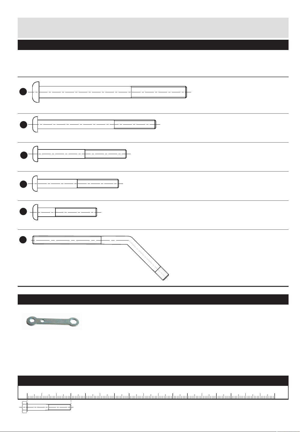
Components - Fittings
Please check you have all the fittings listed belo w
Note: The quantities below are the correct amount to complete the assembly. In some cases more fittings
may be supplied than are required.
A
M8 x 10cm Screw x 6
B
M6 x 8cm Screw x 4
D
M6 x 6cm Screw x 8
E
M6 x 5,5cm Screw x 4
F
M6 x 4cm Screw x 4
G
M6 Screw x 2
Tools required
(Supplied)
Ruler - Use this ruler to help correctly identify the screws
0 5 10 15 20 25 30 35 40 45 50 55 60 65 70 75 80 85 90 95 100
The screws length is measured from the head to the point (30mm screw shown) .
3
105
110 115 120 125 130 135 140 145 150 155 160 165 170
Page 5
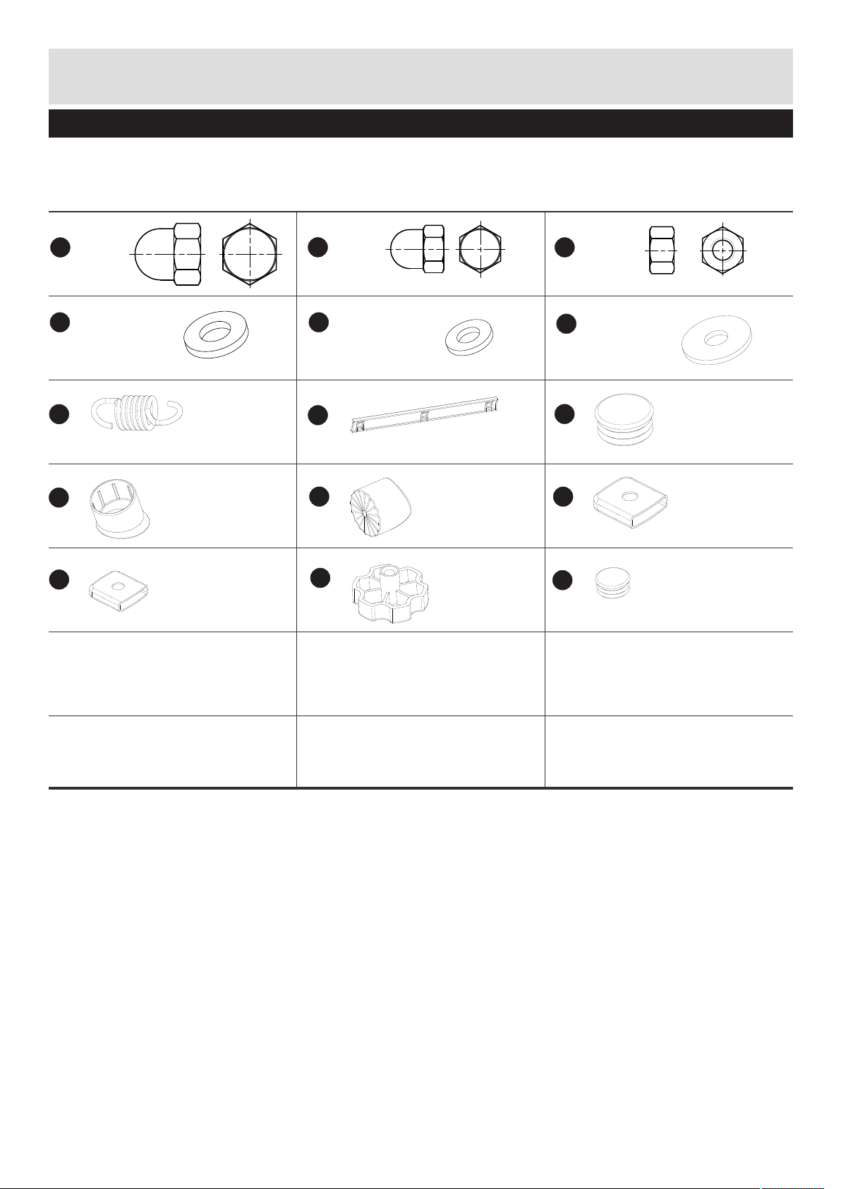
Components - Fittings
Please check you have all the fittings listed belo w
Note: The quantities below are the correct amount to complete the assembly. In some cases more fittings
may be supplied than are required.
H
M8 Nut x 6
K
Ø8 x 12
N
Spring x 2
Q
T
Ø45 x 4
x 8
I
M6 Nut x 22
L
Ø6 x 36
O
28 x 2.5 cm
R
U
x 2
x 2
x 2
J
M6 Nut x 2
M
Ø6 x 2
P
Ø45 x 2
S
x 4
V
Ø28 x 8
4
Page 6

Assembly Instructions
Step 1
Insert the plastic foot Q
onto the end of the back
1
legs 1
Q
2x
1
Q
1
Q
Step 2
a: Insert the plastic cap
P
P into the end of front
2
legs 2
Note:
Pay attention to the
position of the holes
b: Insert the plastic foot
Q
Q onto the other end of
the front legs 2
2
2x
a:
P
2
2
P
b:
2
Q
Q
5
Page 7

Assembly Instructions
Step 3
Assemble back leg 1
and front leg 2 together
with plastic spacer O
using screws A ,
washers K and nuts H .
Note:
Do not fully tighten
bolts.
Repeat with the
remaining legs.
2
A
K
1
O
H
2x
H
K
1
1
1
H
K
O
K
2
K
A
H
K
A
H
K
O
K
K
A
A
Step 4
Assemble the top 3 with
the legs using screws A ,
washers K and nuts H .
K
3
A
H
2
3
H
1
2
1
2
K
1
3
K
A
2
6
Page 8

Assembly Instructions
Step 5
fix the plastic caps S
onto the side bar 9
S
9
Step 6
Assemble the side bar 9
with the legs using
screws D , washers L
and nuts I.
Note:
Pay attention to the
position of the holes
D
L
I
L
2x
9
S
S
9
9
L
9
S
L
D
Step 7
Insert the plastic caps
V
V into the end of one
cross bar 10
10
10
I
9
D
L
L
I
2
L
D
V
9
10
I
L
V
V
7
Page 9

Assembly Instructions
Step 8
Assemble the cross bar
10
10 with the back legs
using screws B, washers
L
L and nuts I
Note:
Do not fully tighten
bolts.
B
I
9
Step 9
Insert the plastic caps V
into the end of the other
cross bar 10
10
V
1
L
B
L
B
10
I
L
I
L
10
9
V
Step 10
Assemble the cross bar
10 9
10 with the side bars
using screws D, washers
L
L and nuts I
Note:
Do not fully tighten
bolts.
D
I
10
10
V
V
10
10
L
L
9
D
D
L
I
I
L
9
9
8
Page 10

Assembly Instructions
Step 11
Insert the plastic caps V
into the end of the
armrests 7
7
V
Step 12
Assemble the two seat
support 6 together
using screws D ,
washers L and nuts I
6
D
L
I
2x
I
L
V
V
7
V
6
6
L
D
I
V
6
I
7
D
Step 13
Assemble the left armrest
7
7 with the seat support
6 using screws E ,
6
washers L and nuts I
L
E
I
6
D
6
L
7
E
7
L
E
I
L
I
L
6
E
7
E
9
Page 11

Assembly Instructions
Step 14
Assemble the right
armrest 7 with the seat
support 6 using screws
E
E , washers L and nuts
I
I
7
6
L
6
E
7
E
L
I
L
I
6
L
7
E
7
E
L
Step 15
Fix the plastic caps T
onto the seat support bar
8
8
T
Step 16
Assemble the left back
seat support bar 8 to
the seat support 6 using
screw F , washers L
and nuts I
F
I
8
6
L
4x
F
T
8
T
8
T
8
I
8
L
10
L
6
F
Page 12

Assembly Instructions
Step 17
Assemble the right back
seat support bar 8 to
the seat support 6 using
screw F , washers L and
nuts I
F
I
8
6
L
Step 18
Assemble the left front
seat support bar 8 to
the armrest 7 using
screw F , washers L
and nuts I
F
I
8
7
LL
8
6
8
F
L
F
L
I
Step 19
Assemble the right front
seat support bar 8 to the
armrest 7 using screw
F
F , washers L and nuts
I
I
7
8
LL
8
I
L
8
L
F
7
F
8
8
F
F
L
L
I
7
11
Page 13

Assembly Instructions
Step 20
Insert the springs N into
the seat support bars 8
N
8
N
N
8
8
N
Step 21
Fix the spring N to the
3
top 3
N
Step 22
Fix the nuts J to the pin
G
G , deep in the longest
thread.
LJ
3
3
N
J
2x
G
12
J
G
Page 14

Assembly Instructions
Step 23
Insert the pin G through
the plastic joint R by the
shortest thread.
Push it as far as the nut
J
J touches the plastic
R
joint R
G
R
Step 24
Fix the plastic joint R to
the top 3 using the
washer L and the nut
L
I
I
Note:
the longest thread of
the pins G have to be
horizontal after fixing
3
LL
G
R
2x
R
G
R
3
R
3
L
I
R
Step 25
Fix one roof bar 4 to the
G
pin G using the washer
L
M
M and the wheel U
4
U
U
U
M
4
G
R
4
M
13
Page 15

Assembly Instructions
Step 26
Insert the roof poles 5
into the canopy's slots
11
6
11
Note:
Let the roof poles pass
through the complete
slots
5
Step 27
Insert the roof poles 5
into the assembled roof
4
bar 4
5
11
5
5
5
4
11
4
Step 28
Insert the roof poles 5
into the other roof bar 4
5
11
11
5
4
4
5
5
5
14
4
Page 16

Assembly Instructions
Step 29
4
Fix the other roof bar 4
to the pin G using the
washer M and the wheel
U
U
G
M
6
4
Tighten completely all
bolts.
Assembly is complete.
M
U
M
U
15
 Loading...