

Page 1
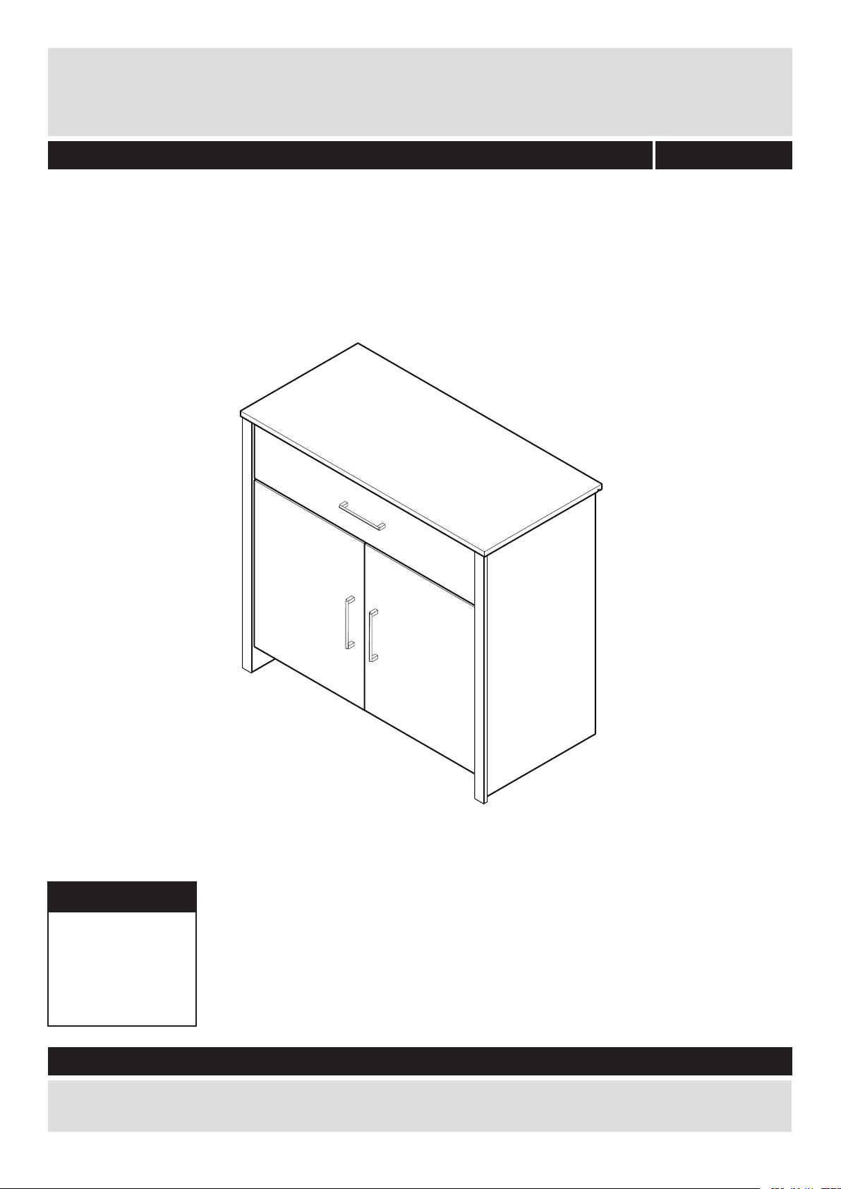
2 Door 1 Drawer Sideboard
Assembly Instructions - Please keep for future reference
041 xx 6005
459/1113
Dimensions
Width - 80.6cm
Depth - 38.8cm
Height - 73.6cm
Important - Please read these instructions fully before starting assembly
If you need help or have damaged or missing parts, call the Customer Helpline: 01709534123
Please turn to back page for important information when contacting Customer Helpline.
Rev A - 29/09/15
Page 2
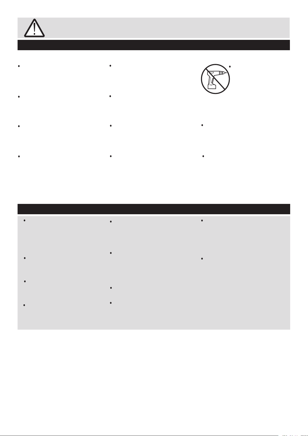
Safety and Care Advice
Important - Please read these instructions fully before starting assembly
Check you have all the
components and tools listed on
pages 2 and 3.
Remove all fittings from the
plastic bags and seperate them
into their groups.
Keep children and animals
away from the work area, small
parts could choke if swallowed.
Make sure you have enough
space to layout the parts before
starting.
Care and maintenance
Do not stand or put weight on
the product, this could cause
damage.
Assemble the item as close
to its final position (in the same
room) as possible.
Assemble on a soft level
surface to avoid damaging the
unit or your floor.
Parts of the assembly will be
easier with 2 people.
We do not
recommend the
use of power
drill/drivers for
inserting screws,
as this could damage the unit.
Only use hand screwdrivers.
Do Not dispose of packaging
until assembly complete.
Dispose of all packaging
carefully and responsibly
when assembly complete.
To protect the furniture,
position the furniture out of
direct sunlight and away from
direct heat sources such as
radiators and fires.
Do not place the furniture in
excessively dry and humid
conditions.
From time to time check that
there are no loose screws on
this unit.
Always lift furniture when
moving it (do not drag)
otherwise the joints may be
damaged.
Do not place hot or cold
objects on the surface, always
use protective mats to avoid
marking the furniture.
This product should not be
discarded with household
waste. Take to your local
authority waste disposal centre.
Clean spills up immediately
Dust surfaces with a soft, dry,
lint free cloth.
More stubborn marks can be
removed using a damp
(not wet) cloth. Wipe the
surface dry immediately
using a soft lint free cloth.
Do not use detergents, abrasive
cleaning products or cleaning
products that contain ammonia,
solvents or silicone as these
may damage the surface finish.
1
Page 3
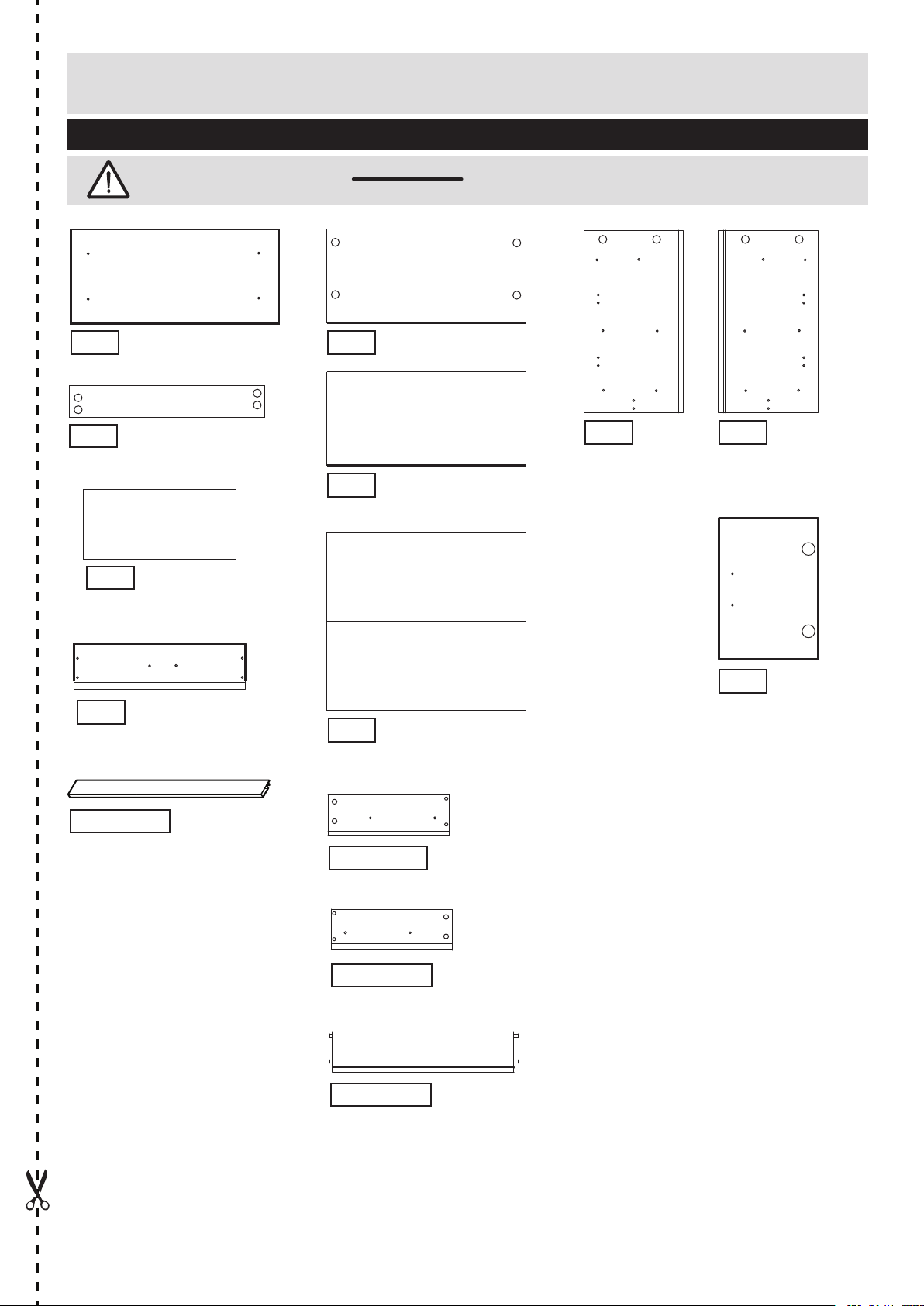
Components - Panels
Please check you have all the panels listed below
Important - Thick lines indicate finished edges
0008
8817
0012
Draw Front
(73.2x15.7cm)
Top (80.6x38.8cm)
Plinth (73.6x76cm)
9321
Drawer Bottom
(71.4x29.8cm)
0009
0014
8822
Backpanel
(74.6x64.4cm)
Bottom (73.6x35.2cm)
Shelf (73.6x33.0cm)
0010
Left End Panel
(72x38.2m)
0011
Right End Panel
(72x38.2cm)
0013
Door x 2
(47.6x36.5cm)
684xx2561
Trim x 2
(720x50x12cm)
622xx7006
Left drawer side (30x12cm)
623xx7006
Right drawer side (30x12cm)
624xx7028
Drawer back (70.3x12cm)
2
Page 4
If you have damaged or missing components, call the
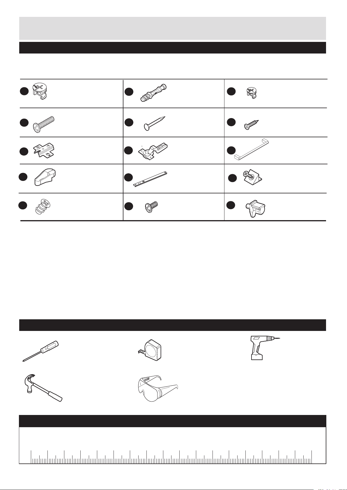
Components-Fittings
Customer Helpline: 01709 534123 Please turn to back page
for important information when contacting Customer Helpline.
Please check you have all the fittings listed below
Note: The quantities below are the correct amount to complete the assembly, In some case more fittings
may be supplied than are required.
M
A
D
G
J
Large cam x 12
Code 760001103
18mm bolt x 6
Code 700002021
Hingeplate x 4
Code 653006000
Panel Pin Locator
Code 684004501
8mm screw x 4
Code 700003510
H
E
K
N
B
Metal dowel x 16
Code 760003004
Panel pin x 8
Code 760001012
Hinge x 4
Code 652001120
Runner x 2
Code 760001040
9mm bolt x 2
Code 690001078
C
F
I
L
P
Small cam x 4
Code 760003005
12mm screw x 8
Code 690001008
Handle x 3
Code 644003511
Panel Holder x 3
Code 680003505
Shelf stud x 4
Code 681003001
Tools required
Cross headed screwdriver
(small)
Small Hammer
Tape Measure
Eye protection
(when using a
hammer)
Ruler - Use this ruler to help correctly identify the screws
mm
10
0
20
30
3
40
50
60
70
80
90
100
110
120
130
140
150
Drill
160
170
Page 5
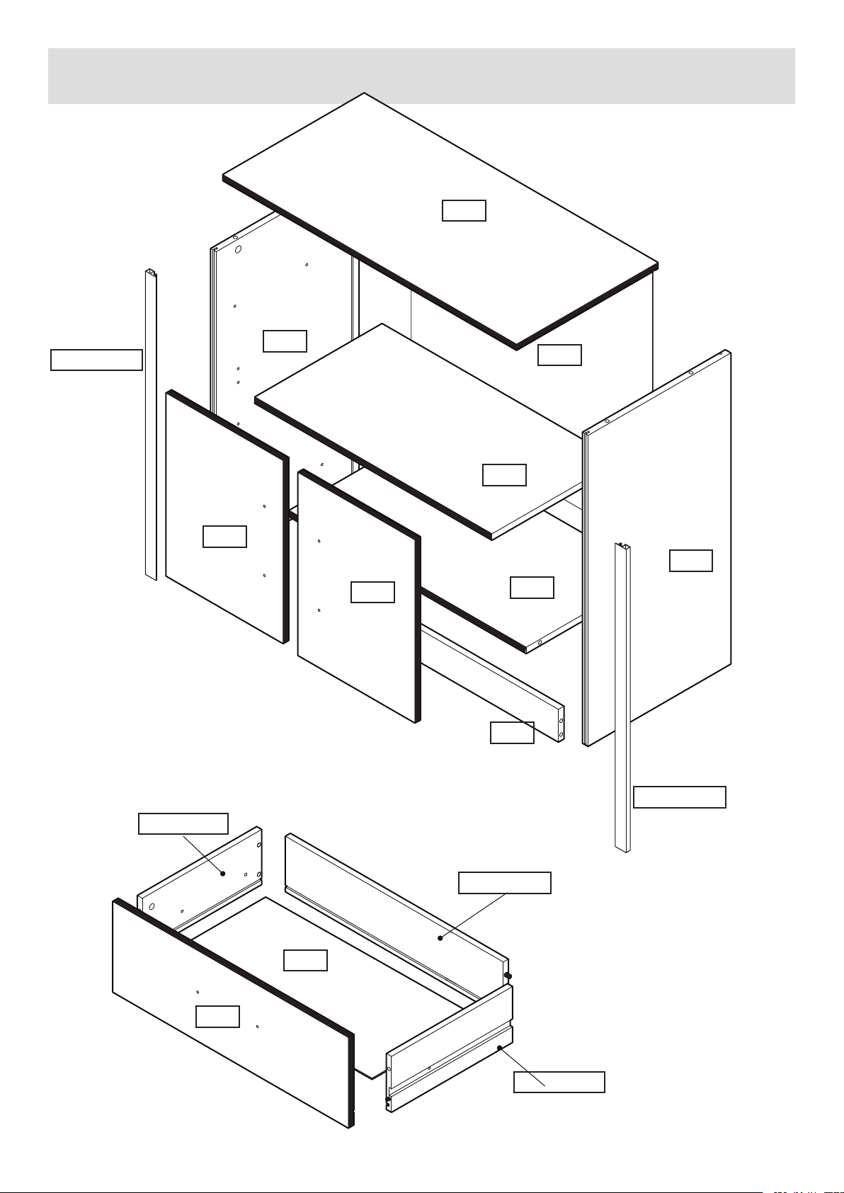
Exploded View
Please check you have all the fittings listed below
0008
684xx6530
0013
0010
0013
8822
0014
0011
0009
8817
622xx7006
0012
684xx6530
624xx7028
9321
623xx7006
4
Page 6
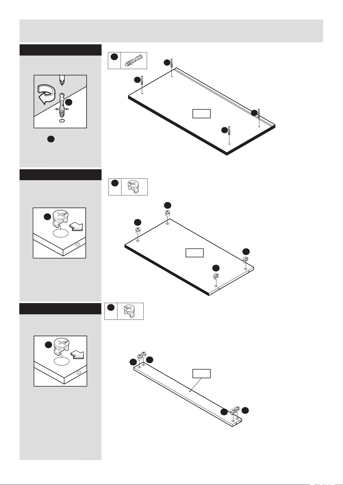
Assembly Instructions
Step 1
Fitting dowels to top
panel.
B
Note: Insert metal
dowels as far as
B
shown by arrows.
Do not over tighten.
Step 2
Fitting cams to the
bottom panel
Fittings you will need for this step:
B
x4
B
B
0008
Fittings you will need for this step:
A
x4
A
B
B
A
Note: Ensure cam
arrow points towards
the edge with hole.
Step 5
Step 3
Fitting cams to the
plinth panel.
A
A
x4
A
0009
A
A
A
A
8817
Note: Ensure cam
arrow points towards
the edge with hole.
5
A
A
Page 7

Assembly Instructions
Step 4
Fitting hingeplates,
cams & dowels to
the left end panel.
G
Ensure that the hinge
points towards the
grooved edge of the
panel.
x4
B
A
x2
A
G
x2
Fitting cams & dowels
to the right end.
A
Note: Ensure cam
A
0010
G
B
G
B
B
B
arrow points towards
the edge with hole.
B
Note: Insert metal
dowels as far as
B
shown by arrows.
Do not over tighten.
Step 5
Attaching runner to
left end
Position the runner so
that the second hole
from the front of the
runner lines up with the
pre-drilled hole nearest
to the edge of the panel.
Use screws to secure
the runner.
Front of runner
Slide the runner forward
revealing the back of the
runner. The second hole
to the back of the runner
should now line up with
the second pre-drilled
hole.
M
K
x1
M
x2
0010
M
M
K
K
6
Page 8

Assembly Instructions
Step 6
Fitting hingeplates,
cams & dowels to
the left end panel.
G
Ensure that the hinge
points towards the
grooved edge of the
panel.
x4
B
A
x2
B
B
B
G
x2
Fitting cams & dowels
to the right end.
A
Note: Ensure cam
B
0011
G
A
G
A
arrow points towards
the edge with hole.
B
Note: Insert metal
dowels as far as
B
shown by arrows.
Do not over tighten.
Step 7
Attaching runner to
right end
Position the runner so
that the second hole
from the front of the
runner lines up with the
pre-drilled hole nearest
to the edge of the panel.
Use screws to secure
the runner.
Front of runner
Slide the runner forward
revealing the back of the
runner. The second hole
to the back of the runner
should now line up with
the second pre-drilled
hole.
M
K
x1
M
x2
K
M
0011
M
K
7
Page 9

Assembly Instructions
Step 8
Attach hinges and
handles to doors
Important:
a: Insert hinges
into holes, ensure
the hinge is straight
(90 degree angle).
90
H
98
H
H
x4
H
D
x4
F
x8
I
x2
H
A
H
0013
B
b: Before securing the
hinges , we recommend
you pre - mark the doors
using a bradawl.
c: Secure hinges to
doors using screws .
H
Bradawl
H
H
F
F
F
C
D
0013
F
F
F
F
0013
H
d: Secure handle to
doors using bolts
Repeat on
remaining door
I
D
0013
D
D
I
8
Page 10

Assembly Instructions
Step 9
Fitting dowels to the
drawer front.
A: Insert 4 metal dowels
B
into the the drawer
front . .
B: Insert small cams
into left
and right
drawer sides.
Note: Ensure cam arrow
points towards the edge
with hole.
0012
622xx7006
623xx7006
B
x4
A
B
C
x4
D
x2
B
B
B
0012
I
x1
B
Right hand side
623xx7006
C
NOTE:
The drawers have been
reduced in size for the
purposes of illustration.
C
C: Insert wooden dowels
in drawer back
624xx7028
into holes in
left
622xx7006
right hand
623xx7006
drawer sides.
D: Slide drawer bottom
into grooves in the left
and right drawer sides
and the drawer back.
C
D
Left hand side
622xx7006
Left hand side
622xx7006
622xx7006
Drawer Back
624xx7028
Right hand side
623xx7006
624xx7028
9321
SLIDE!
Plain chipboard surface
to underside.
9
623xx7006
Page 11

Assembly Instructions
Step 9 - Continued
E: Locate the metal
dowels (already inserted)
in the drawer front into the
small cams in the left and
right hand drawer sides.
Turn the cam 180 degrees
to lock.
Fit 2 bolts through
F:
the pre-drilled holes in
the drawer front
and connect to the handle
I
.
D
0012
E
623xx7006
622xx7006
0012
F
D
D
Step 10
Connect left end panel
to bottom.
Connect the dowels in
the left end panel
into the cams in the
bottom
Turn cams 180° to lock.
0009
0010
0012
I
0010
0009
Finished Edge to The Floor
10
Page 12

Assembly Instructions
Step 11
Connect left end panel
to plinth.
Connect the dowels in
the left end panel
into the cams in the
plinth
Turn cams 180° to lock.
8817
Ensure plinth sits
flush.
Ensure plinth is
not overhanging.
0010
Step 12
Connect right end
panel to bottom and
plinth.
Connect right hand end
panel to bottom
and plinth
0009
Turn cams 180° to lock.
0011
8817
8817
0010
0009
11
0011
8817
Page 13

Assembly Instructions
Step 13
Connect the top panel
to the ends .
Connect the dowels in
the top panel to
end panels and
0011
.
Turn cams 180° to lock.
0008
0010
0010
0008
0011
Step 14
Slide the back panel
8822
into the grooves.
You may need to tilt the
unit onto it’s top to ensure
that the back panel is
located into the groove.
Squaring up the unit.
Important:
Ensure a tape
measure is used
to square up unit!
Before securing the back
it is necessary to square
up the unit.
You can do this by
measuring between
XX - XX and YY - YY
ensuring these are the
same (DIAG 1).
YY
YY
XX
DIAG 1
XX
YY
XX
8822
YY
DIAG 2
XX
XX
YY
XX
YY
DIAG 3
XX
XX
YY
Plain chipboard surface.
YY
If they are not (DIAG 2)
Apply slight pressure as
indicated (DIAG 3) until
they are the same.
Measure to external corners
12
Page 14

Assembly Instructions
Step 15
Attach backpanel to
bottom
Use the panel pin guide
when locating the panel
pins. This will hold the
panel pins vertical and
ensure the correct
distance from the edge.
E
Ensure that the
backpanel is fully
inserted into groove.
E
x8
J
x1
E
8822
Step 16
Add stability blocks.
Slide the thin point of the
stability blocks
between the back panel
and the grooves.
8822
Once inserted fully,
tighten the screws in the
stability blocks.
L
L
x3
L
8822
L
L
L
13
Page 15

Assembly Instructions
Step 17
Attach silver trim
Turn unit over.
Remove protective film
from silver trim.
Warning:
2 people to lift.
Lift with care.
Locate the notch on
silver trim into
groove on left and
0011
right ends.
Ensure the silver
trims are positioned
correctly.
To insert silver trims
use a hammer, place a
cardboard packing piece
between the hammer
and silver trims to
protect the silver
trims.
0010
Fittings you will need for this step:
Silver Trims
(x2)
0010
0011
Step 18
Lift unit up and
Locate shelf studs
Warning:
2 people to lift.
Lift with care.
Push shelf studs
into panels and
0011
.
P
0010
P
P
x4
P
P
0010
0011
14
Page 16

Assembly Instructions
Step 19
Locate shelf onto
shelf studs
Locate shelf
onto shelf studs
0014
Step 20
Locate drawer
P
0014
N
x2
For this step we
recommend you follow
the helpful hints page.
15
Detailed View
N
2nd Hole
Page 17

Assembly Instructions
Step 21
Locate drawers helpful
hints
a: Pull sliding part of
drawer runners out
so they are fully
extended.
K
b: Locate drawer onto
runners.
c: Locate screwdriver
into second threaded
hole in drawer runner .
K
d: Keeping screwdriver
in place push the drawer
in until the screwdriver
pushes against the
panel.
Remove the screwdriver.
A
C
B
K
K
D
K
2nd Hole
e/f: Pull drawer out slowly
and line the front hole in the
drawer side with the 2nd
threaded hole in runner .
Holding runner and
drawer side together
insert bolts through the
drawer side and
into threaded hole in
runner .
Now repeat these
steps for the other
side of the drawer.
N
J
LK
K
E
F
N
2nd Hole
16
Page 18

Assembly Instructions
Step 22
Hanging doors
a: With help, slot door
hinges onto hinge plates.
Ensure screw on hinge
slides into the slot on
hingeplate.
See Diagrams 1, 2 and 3.
b: Tighten screw shown
to lock hinges in
position.
See ‘Hinge adjustment’
page if the doors
need adjusting.
A
B
Diagram 1
Underside view
B
Ensure the underside of screw
B slides into slot on hingeplate.
Diagram 2
B
Hinge correctly attached to
hingeplate.
Diagram 3
17
B
Hinge incorrectly attached to
hingeplate.
Page 19

Assembly Instructions
Step 23
Hinge adjustment
a: To move doors up
or down: loosen screws
shown and move doors
to suit.
Re-tighten screws.
A
b: To move doors in or
out: loosen screw
shown and move doors
to suit.
Re-tighten screws.
c: To move doors left
or right: loosen or
tighten screw as shown.
Be careful not to fully
unscrew.
B
C
18
Page 20

Assembly Instructions
Congratulations! Your unit is complete.
Important Information
If you need help or have damaged or missing parts, call the Customer Helpline:
8am - 4.30pm (Monday to Thursday)
01709 534123
(by contacting the customer service line your statutory rights are not affected)
Please have the following information to hand:
>> Unit Description
>> Product Code
>> Product Colour
>> Place of Purchase
>> Catalogue Ref. No.
>> Item Code
>> Assembly Instructions
We do have an answer machine should you contact us out of office hours, so in addition to
the above information could you leave your name, address, daytime telephone number and
the nature of your call on the answerphone. All calls will be actioned asap.
8am - 2.30pm (Fridays)
You can also e-mail your requests to us at:
customer.helpdesk@addspacefl.co.uk
Alternatively, you can write to us at: Customer Service Department, Addspace Furniture Limited,
Braithwell Way, Hellaby Industrial Estate, Hellaby, Rotherham, South Yorkshire, S66 8QY.
 Loading...