

Argos 2756802 ASSEMBLY INSTRUCTIONS
MADE IN
BRITAIN
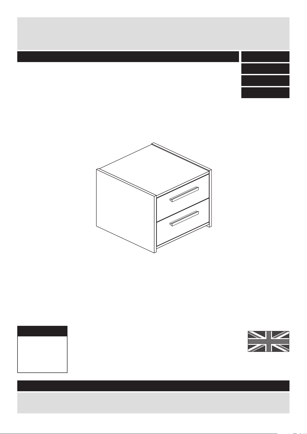
Dimensions
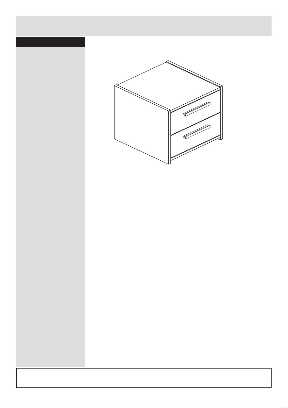
Width - 39.5cm
Depth - 40cm
Height - 39cm
New Sywell - 2 Drawer Bedside
Assembly Instructions - Please keep for future reference
If you need help or have damaged or missing parts, call the Customer Helpline: 08456 400800
Issue 4 - 11/03/15
Important - Please read these instructions fully before starting assembly
282/8417
281/2612
279/9618
268/4792

Safety and Care Advice
Important - Please read these instructions fully before starting assembly
• Warning: This unit weighs
approximately 10kgs.
Please lift with care.
• Check you have all the
components and tools listed on
pages 2 and 3.
• Remove all fittings from the
plastic bags and separate them
into their groups.
• Keep children and animals
away from the work area, small
parts could choke if swallowed.
• Parts of the assembly will be
easier with 2 people.
• Make sure you have enough
space to layout the parts before
starting.
• Do not stand or put weight on
the product, this could cause
damage.
• Assemble the item as close to
its final position (in the same
room) as possible.
• Assemble on a soft level
surface to avoid damaging the
unit or your floor (use opened
out unit carton).
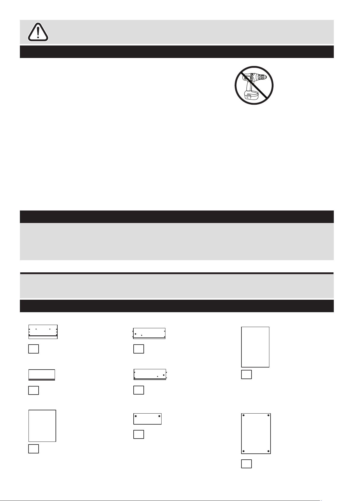
• We do not
recommend the
use of power
drill/drivers for
inserting screws,
as this could damage the unit.
Only use hand screwdrivers.
• Safety note: If there is any
chance of this unit being pulled
over by children etc. it is
recommended that the unit is
secured to a wall using suitable
fixings (not supplied).
• Dispose of all packaging
carefully and responsibly.
1
Care and maintenance
• Only clean using a damp cloth
and mild detergent, do no use
bleach or abrasive cleaners.
• From time to time check that
there are no loose screws on
this unit.
• This product should not be
discarded with household
waste. Take to your local
authority waste disposal centre.
Note: If required the next page
can be cut out and used as
reference throughout the
assembly. Keep this page with
these instructions for future
reference.
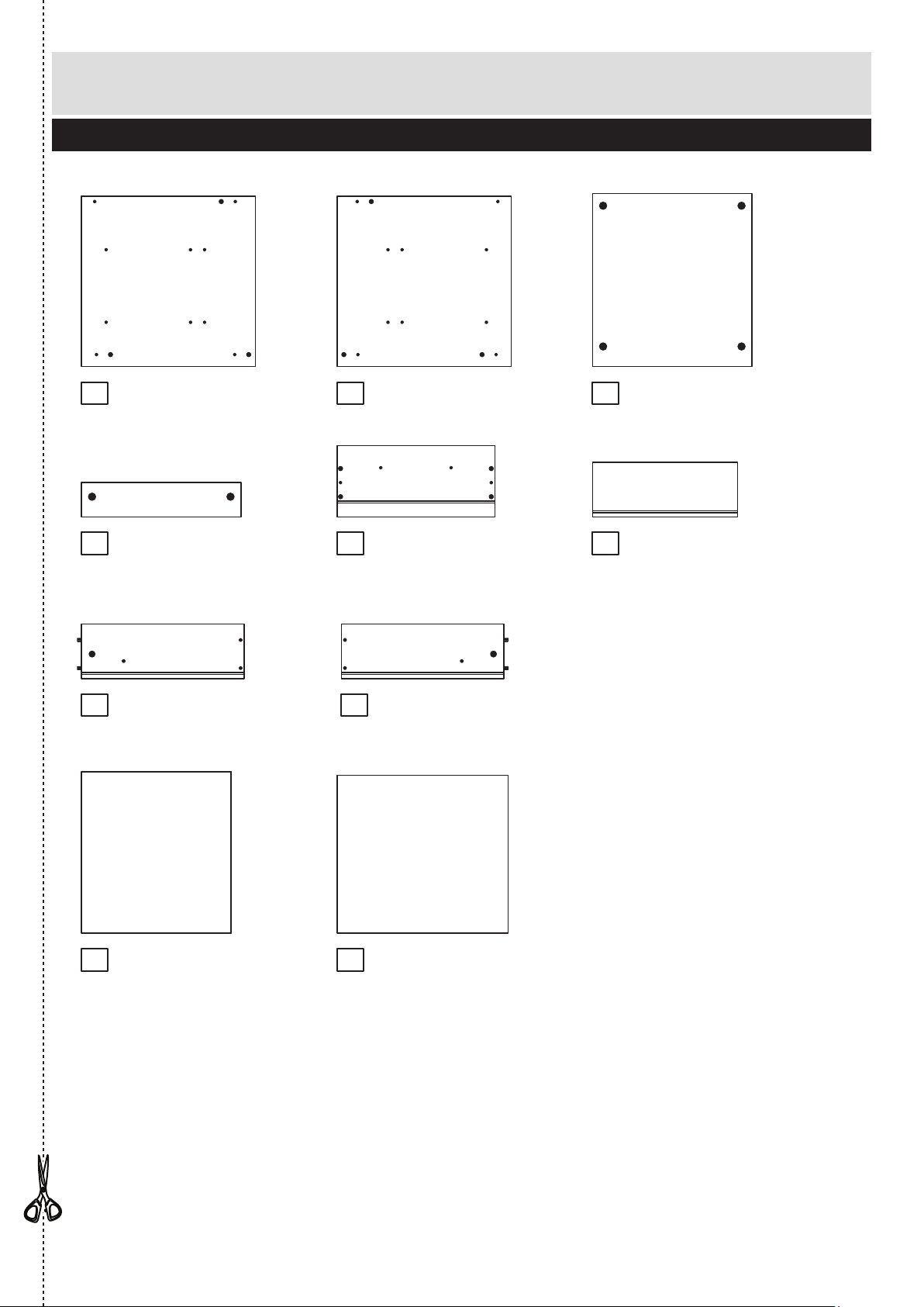
Components - Panels
Please check you have all the panels listed below
2
1
2 3
If you have damaged or missing components, call the
Customer Helpline: 08456 400800 quoting the reference
numbers below
4
Top (D2541A)
(363 x 394mm)
Back (X389-359)
(389 x 359mm)
Left Side (D2542A)
(388 x 396mm)
Right Side (D2543A)
(388 x 396mm)
Rail (D2544A)
(363 x 78mm) x 2
5
Drawer Front (D2545A)
(359 x 162mm) x 2
Drawer Base (T342-367)
(342 x 367mm) x 2
9 10
7
Drawer Back (W330-124)
(330 x 124mm) x 2
8
6
Left Drawer Side (W370-124LH)
(370 x 124mm) x 2
Right Drawer Side (W370-124RH)
(370 x 124mm) x 2

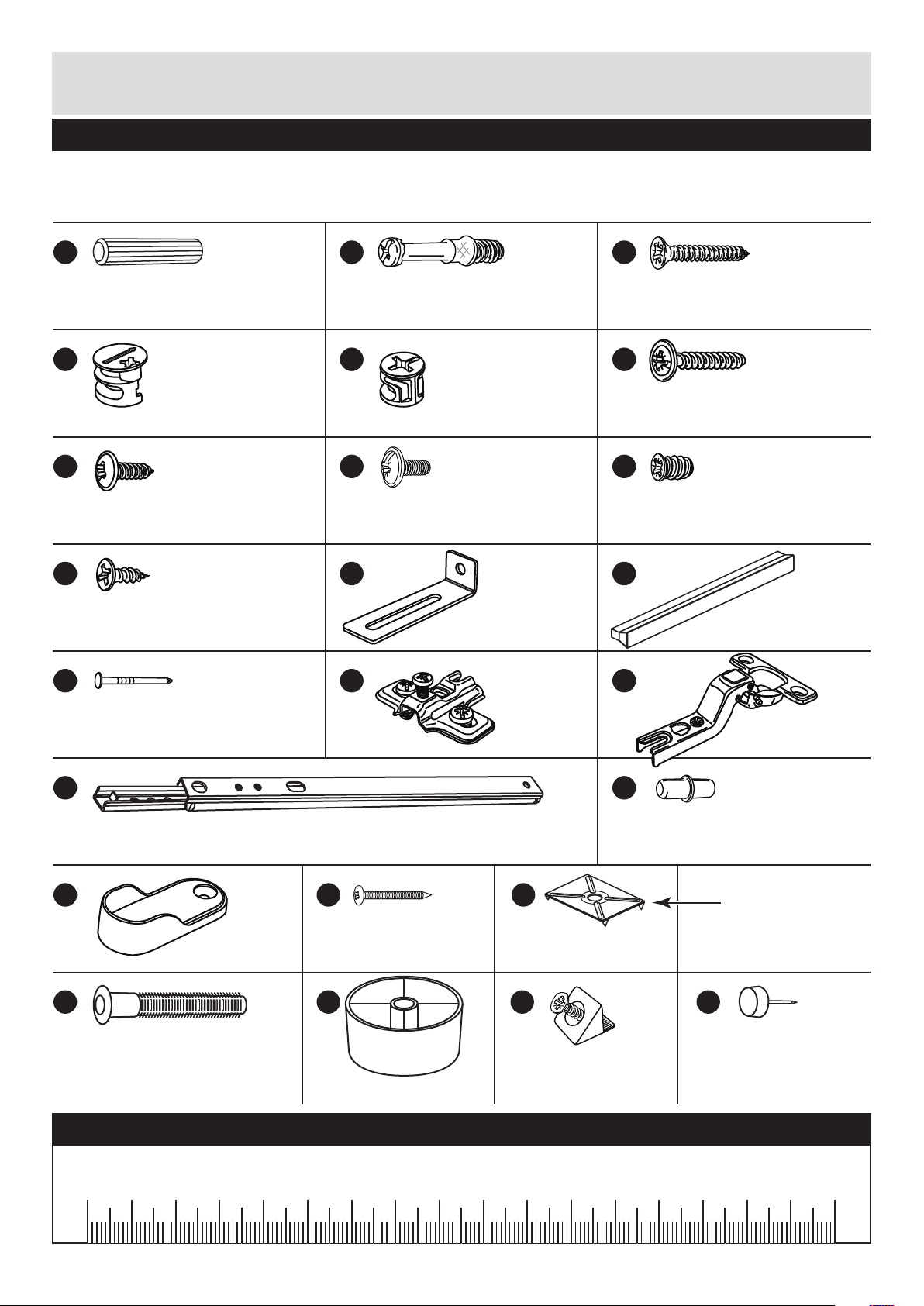
Please check you have all the fittings listed below
Tools required
3
Components - Fittings
If you have damaged or missing components, call the
Customer Helpline: 08456 400800 quoting the reference
numbers below
Note: The quantities below are the correct amount to complete the assembly. In some cases
more fittings may be supplied than are required.
A
Wooden dowel (F22) x 6
B
Metal dowel (F901) x 12
C
D E F
G H I
Rule Scissors Hammer
Eye protection
(when using a
hammer or drill)
Cross-head
screwdriver
Ruler - Use this ruler to help correctly identify the screws
mm 10 20 30 40 50 60 70 80 90 100 110 120 130 140 150 160 170
J K
9mm Screw (F74) x 4 9mm Screw (F73) x 8
Drawer runner (F1004) x 4
Electric drill
(do not use for
fitting screws)
Knock-in Peg (F171) x 8
Small locking
nut (F3) x 4
Large locking
nut (F900) x 8
Nail (F51) x 10
Handle (F315) x 2
25mm Screw (F95) x 4
M
Plastic Nail (F91) x 4
L
Wedgefix (F639) x 4

Assembly Instructions
4
If you have damaged or missing components, call the
Customer Helpline: 08456 400800 quoting the reference
numbers below
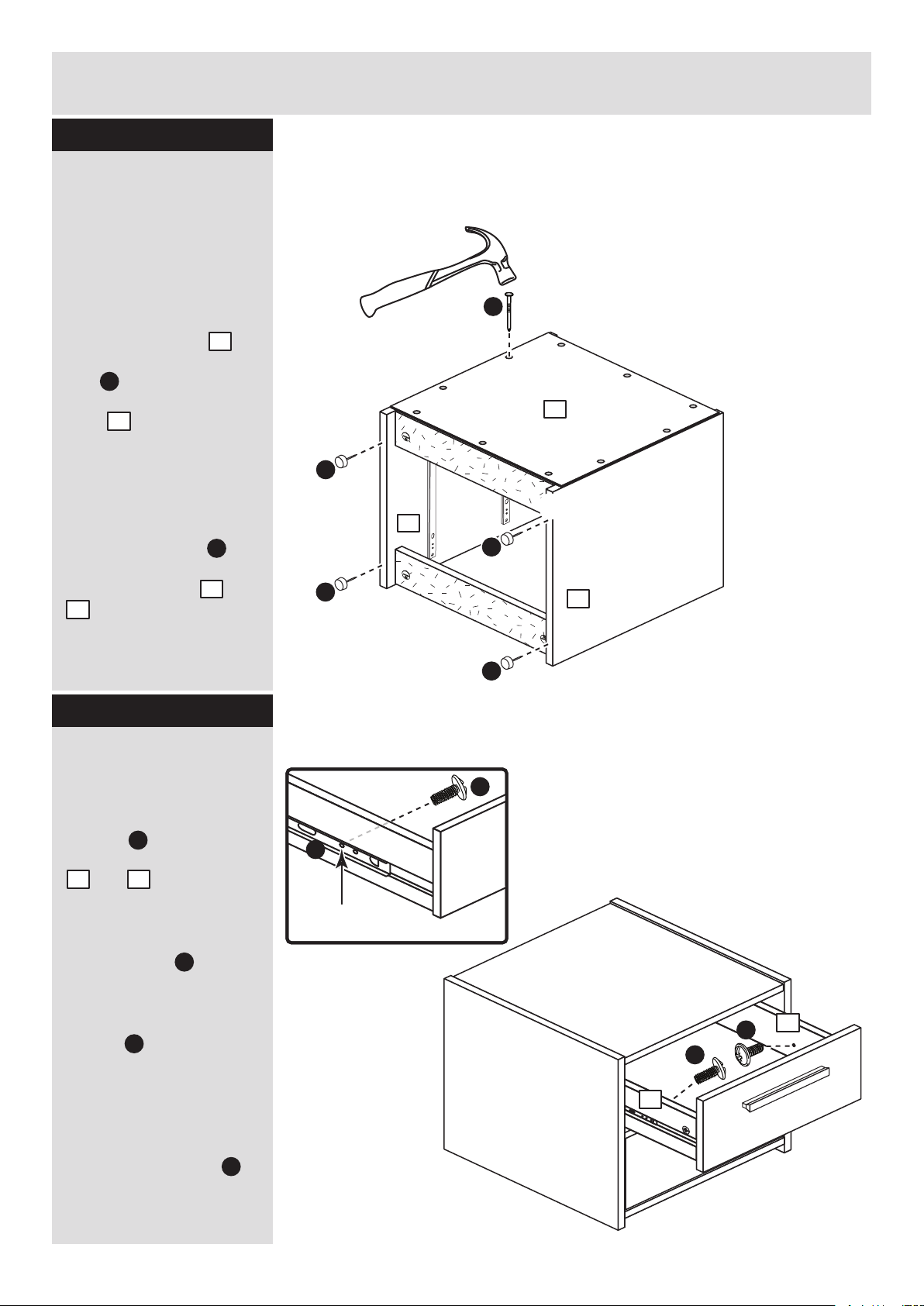
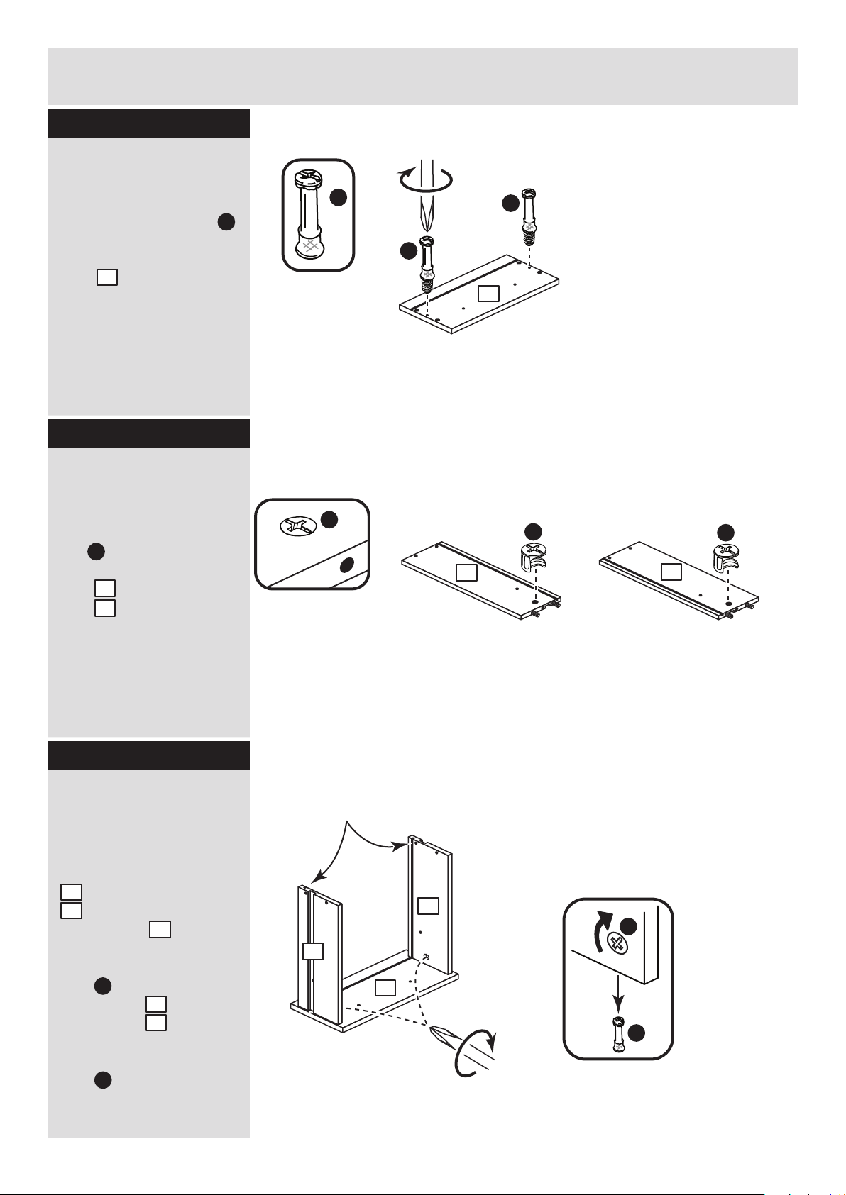
Step 1
x 2
x 2 x 2
x 2
B
Prepare the drawer
fronts
Screw 2 metal dowels
into the holes shown on
the back of each drawer
front .
Note: Tighten the metal
dowels up fully against
the panels.
B
5
Prepare the drawer
sides
Insert a small locking
nut into the hole
shown on the left drawer
side and right drawer
side .
Note: Arrow on locking
nut must point towards
hole in edge of panel.
E
7
8
Step 2
Step 3
B
B
5
Attach the drawer
sides to the drawer
front
Push the left drawer side
. and right drawer side
. onto the back of the
drawer front .
Turn the small locking
nuts on the left
drawer side and right
drawer side .
Note: Turn the locking
nuts clockwise to
secure panels - more
than 1/2 a turn.
7
8
5
E
7
8
Note: The locking nuts can be on
either surface of the drawer sides.
Make sure that the small groove
is on the inside, as shown.
E
5
E
B
B
E
Small groove
9
Note: Due to the manufacturing process, the holes for the
locking nut can be on either surface of the drawer sides.
E
E
7
8
8
7

9
8
5
7
6
Assembly Instructions
5
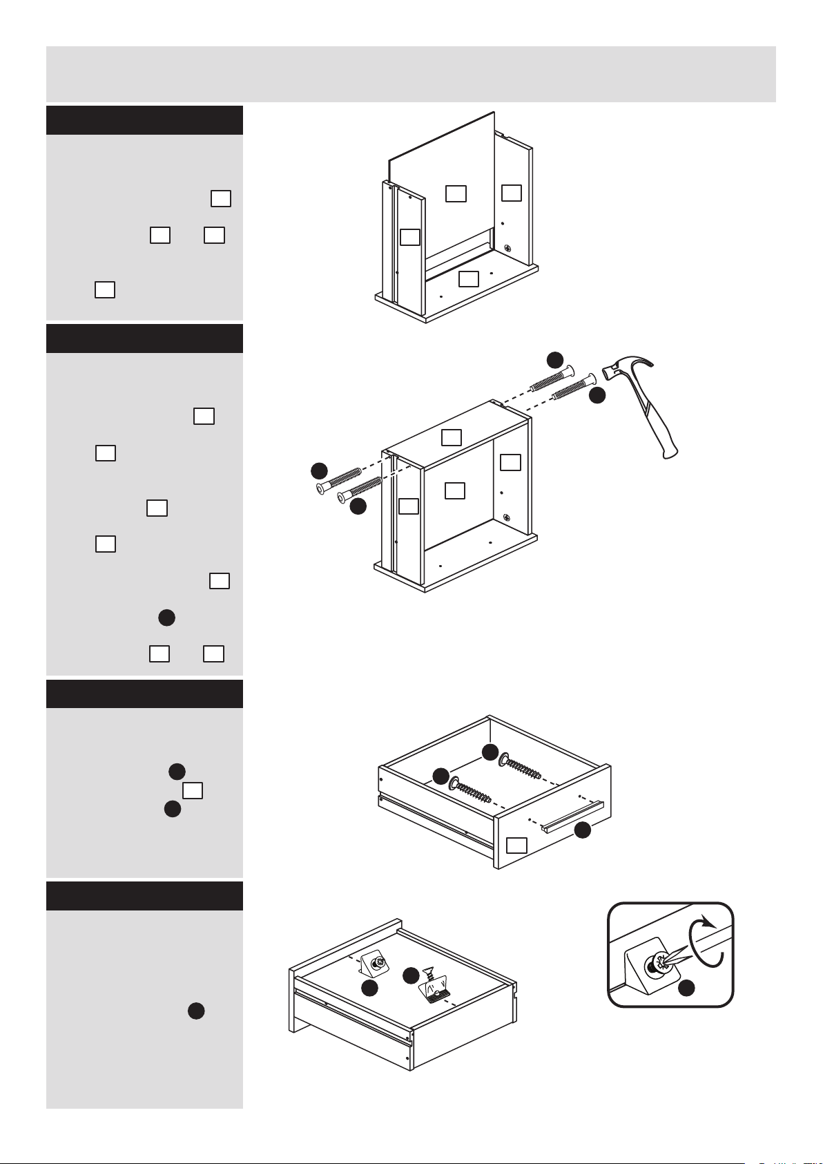
Step 4
Step 5
Fit the drawer base
Slide the drawer base
down the grooves in the
drawer sides and
and down into the
groove in the drawer
front .
9
7 8
5
C
C
x 2
Fit the drawer back
Fit the drawer back
down onto the drawer
base .
Make sure that the
drawer base fits into
the groove in the drawer
back .
Hold the drawer back
in position and tap the
knock-in pegs
through the holes in the
drawer sides and .
6
9
9
6
6
C
7 8
C
C
Attach the handle
Attach a handle to
each drawer front
using 2 screws .
J
F
Step 6
5
x 2
5
F
F
J
x 2
Step 7
Fit the wedgefixes
Turn the drawer
assemblies over and
slide 2 wedgefixes
into the front and back
grooves, as shown, and
tighten up the screws.
L
L
L
L
I
x 2
9
8
7
5
Finished front edge
Assembly Instructions
6
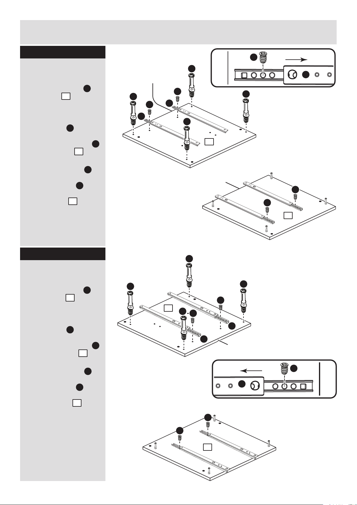
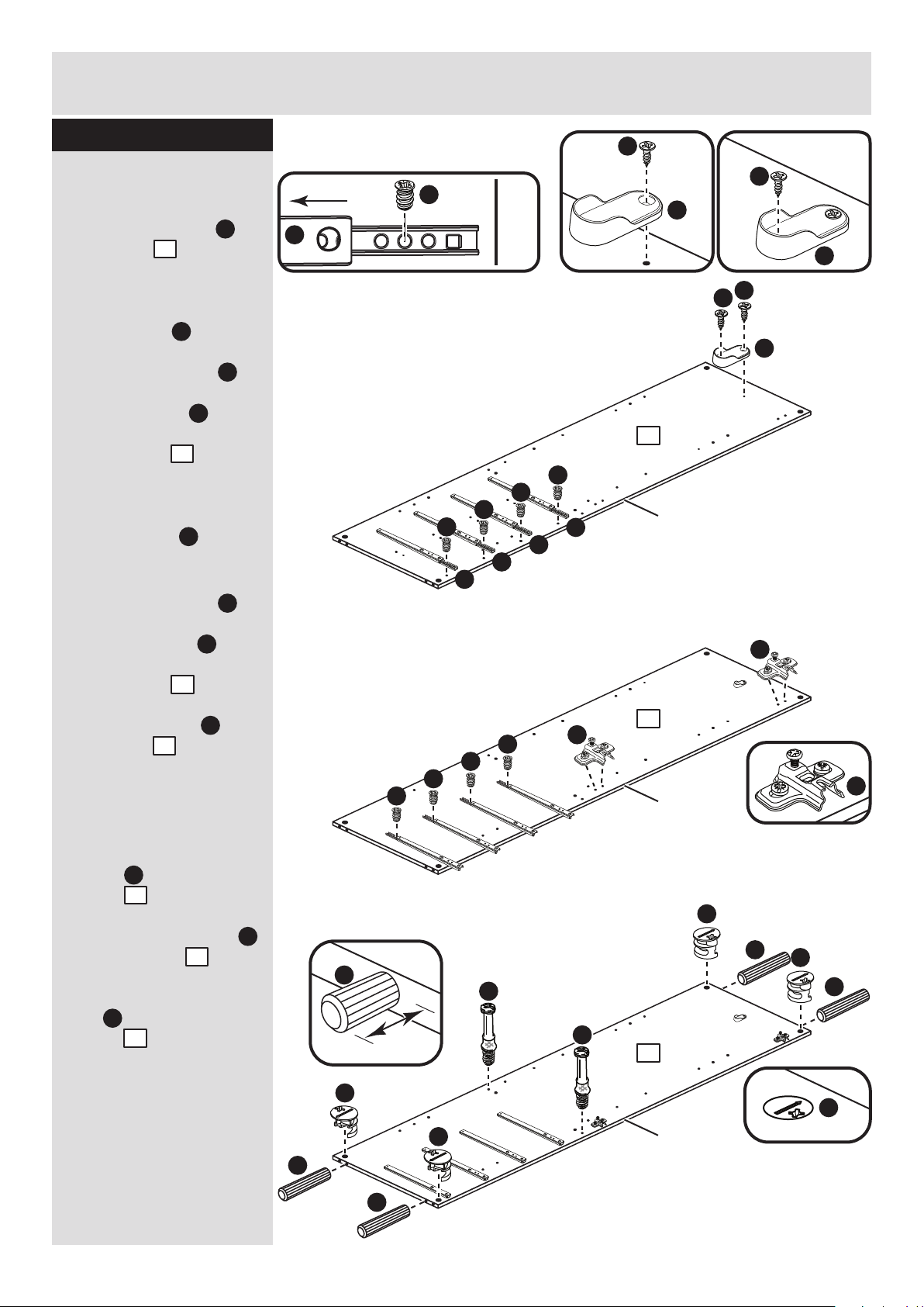
Step 7
Prepare the left side
a: Place 2 runners on
the left side . Slide
back the top of the
runner and use the 2nd
hole from the front to fit
the 1st screw .
Screw 4 metal dowels
into the left side .
b: Slide the runner
back the other way and
fit the 2nd screw into
the corresponding hole
in the left side .
K
1
Finished
front edge
H
K
H
K
B
B
B
H
K
B
H
H
H
Finished front edge
1
1
a:
a:
b:
b:
B
1
K
H
1
Finished
front edge
Finished
front edge
H
K
H
K
H
K
B
B
B
B
H
H
Step 8
Prepare the right side
a: Place 2 runners on
the right side . Slide
back the top of the
runner and use the 2nd
hole from the front to fit
the 1st screw .
Screw 4 metal dowels
into the right side .
b: Slide the runner
back the other way and
fit the 2nd screw into
the corresponding hole
in the right side .
K
2
H
B
2
K
H
2
2
2
Finished
front edge
Finished
front edge
A
Assembly Instructions
7
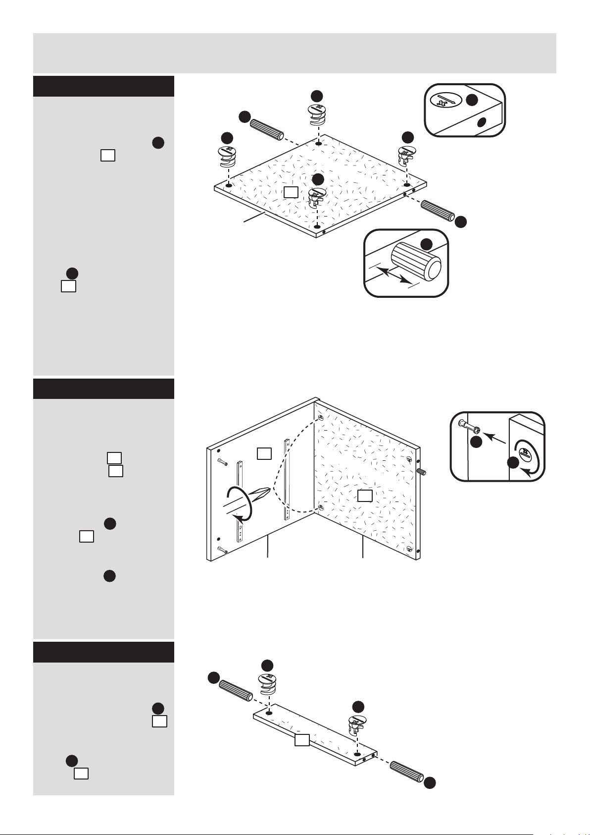
Step 9
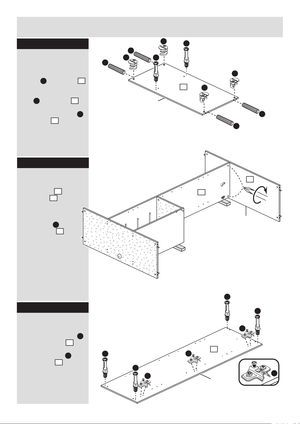
Prepare the top
Tap 2 wooden dowels
into the top .
Note: Wooden dowels
must not stick out from
the edge by more than
10mm or they may
damage other panels.
Insert 4 large locking
nuts into the
top .
Note: The arrow on the
locking nut must point
towards the hole in the
edge of the panel.
Fit the top to the right
side
Push the top onto
the right side .
Use a screwdriver to
tighten the 2 large
locking nuts fitted to
the top .
Note: Turn the large
locking nuts as far as
they will go - more than
1/2 a turn.
Step 10
Step 11
D
D
D
D
D
A
10mm
A
A
3
D
3
3
plain chipboard surface
Finished
front edge
3
2
D
3
D
B
D
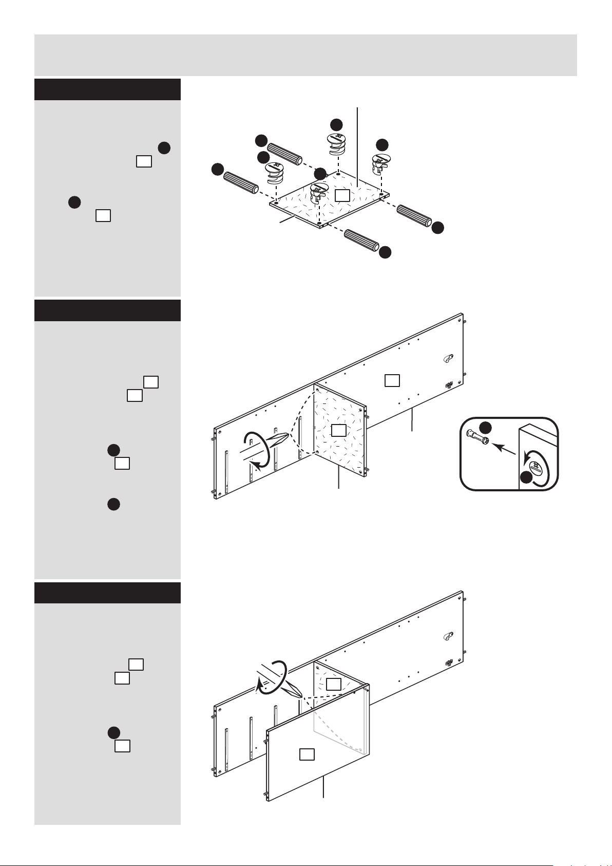
Prepare the 2 rails
Tap 2 wooden dowels
into each of the 2 rails .
Insert 2 large locking
nuts into each of the
2 rails .
A
4
D
4
x 2
2
plain chipboard surface
3
A
A
plain chipboard surface
4
D
D

Assembly Instructions
8
Step 12
Step 13
Fit the left side
Push the left side
onto the assembly.
Use a screwdriver to
tighten the 4 large
locking nuts fitted to
the top and the 2
rails .
D
1
3
4
Fit the 2 rails
Push the 2 rails onto
the right side .
Use a screwdriver to
tighten the large locking
nut fitted to each of
the 2 rails .
D
4
2
4
2
4
4
Note: Support this
rail until the left
side has been fitted
in the next step.
4
4
3
1
Assembly Instructions
9
Step 14
b:
Fit the back and
plastic nails
a: Square up the unit by
making sure that
measurement x to x
equals y to y.
b: Place the back
onto the unit.
Nail around the
outside edges of the
back .
Note: Nails should be
spaced about 150mm
apart.
10
I
The measurement from top corner X to bottom corner X must be
equal to the measurement from top corner Y to bottom corner Y
a:
10
Fit the drawers
Starting with the bottom
drawer, slide both the
runners forward and
locate the drawer sides
. and between
them, lining up the holes
in the drawer wrap with
the 2nd 'threaded' holes
in the runners .
Working from the inside
of the drawer, insert 2
screws through the
sides and out into the
2nd threaded hole in the
runner.
Note: Do not overtighten the screws .
If they catch on the
runner you may need
to loosen them slightly.
G
7 8
K
K
G
Step 15
G
G
2nd threaded
hole
K
G
7
8
y
y
x
x
I
10
Tap 2 plastic nails
into the bottom edge of
each of the sides and
. .
M
1
2
Stand the unit up
for the next step.
M
2
1
M
M
M
Assembly Instructions
10
If you need help or have damaged or missing parts, call the Customer Helpline: 08456 400800
and quote the reference numbers on the component pages.
Argos Ltd, 489-499 Avebury Boulevard, Central Milton Keynes, MK9 2NW
Step 16
Assembly is complete

ALR3011

MADE IN
BRITAIN
Dimensions
Width - 104cm
Depth - 49.5cm
Height - 171cm
New Sywell - 4 Drawer 3 Door Robe
Assembly Instructions - Please keep for future reference
If you need help or have damaged or missing parts, call the Customer Helpline: 08456 400800
Issue 4 - 07/10/14
Important - Please read these instructions fully before starting assembly
282/7023
258/1376
281/6096
278/9130
Safety and Care Advice
Important - Please read these instructions fully before starting assembly
• Warning: This unit weighs
approximately 73kgs.
Please lift with care.
• Check you have all the
components and tools listed on
pages 1, 2 and 3.
• Remove all fittings from the
plastic bags and separate them
into their groups.
• Keep children and animals
away from the work area, small
parts could choke if swallowed.
• Parts of the assembly will be
easier with 2 people.
• Make sure you have enough
space to layout the parts before
starting.
• Do not stand or put weight on
the product, this could cause
damage.
• Assemble the item as close to
its final position (in the same
room) as possible.
• Assemble on a soft level
surface to avoid damaging the
unit or your floor (use opened
out unit carton).
Care and maintenance
• Only clean using a damp cloth
and mild detergent, do no use
bleach or abrasive cleaners.
• From time to time check that
there are no loose screws on
this unit.
• This product should not be
discarded with household
waste. Take to your local
authority waste disposal centre.
• We do not
recommend the
use of power
drill/drivers for
inserting screws,
as this could damage the unit.
Only use hand screwdrivers.
• Safety note: It is
recommended that this unit is
secured to a wall using the
bracket supplied.
• Dispose of all packaging
carefully and responsibly.
Components - Panels
Please check you have all the panels listed below
If you have damaged or missing components, call the
Customer Helpline: 08456 400800 quoting the reference
numbers below
1 4
5
3
7
2
6
8
1
Drawer Front (D2575A)
(333 x 162mm) x 4
Drawer Base (T315-367)
(315 x 367mm) x 4
Drawer Back (W304-124)
(304 x 124mm) x 4
Left Drawer Side (W370-124LH)
(370 x 124mm) x 4
Right Drawer Side (W370-124RH)
(370 x 124mm) x 4
Rail (D2598A)
(322 x 125mm)
Horizontal (D2573A)
(337 x 467mm)
Shelf (D2574A)
(322 x 468mm) x 3

Components - Panels
Please check you have all the panels listed below
2
9
10
If you have damaged or missing components, call the
Customer Helpline: 08456 400800 quoting the reference
numbers below
Left Side (D2560A)
(1711 x 496mm)
Right Side (D2569A)
(1711 x 496mm)
Hanging Rail (FHR666)
(666mm long)
12
Top (D2568A)
(1011 x 494mm)
Base (D2570A)
(1011 x 494mm)
Upright (D2571A)
(1656 x 468mm)
Large Door (D2563A)
(1650 x 333mm) x 2
Centre Door (D2576A)
(990 x 333mm)
Small Back (X1682-340)
(1682 x 340mm)
Large Back (X1682-694)
(1682 x 694mm)
11
13
14
15
Divider (D2572A)
(675 x 468mm)
17
16
18 19
Please check you have all the fittings listed below
3
Components - Fittings
If you have damaged or missing components, call the
Customer Helpline: 08456 400800 quoting the reference
numbers below
Note: The quantities below are the correct amount to complete the assembly. In some cases
more fittings may be supplied than are required.
Ruler - Use this ruler to help correctly identify the screws
mm 10 20 30 40 50 60 70 80 90 100 110 120 130 140 150 160 170
A
Wooden dowel (F22) x 20
B
Metal dowel (F901) x 28
C
D E F
G H I
L
M
J K
9mm Screw (F74) x 8 9mm Screw (F73) x 16
P
Drawer runner (F1004) x 8
13mm Screw (F79) x 1
Small locking
nut (F3) x 8
Large locking
nut (F900) x 20
Nail (F51) x 37
Bracket (F327) x 1
Handle (F315) x 7
13mm Screw (F63) x 20
ON
Hinge plate
(F523) x 8
Hinge (F522) x 8
Q
25mm Screw (F95) x 14
R
Rail Holder
(F891) x 2
S
Nail screw (F277) x 5
Shelf stud (F110) x 12
V
Foot (F854) x 1
25mm Screw (F50) x 1
Knock-in Peg (F171) x 16
U X
Plastic Nail (F91) x 4
W
Wedgefix (F639) x 8
T
Back holder (F276) x 5
These can
also be round
Assembly Instructions
4
If you have damaged or missing components, call the
Customer Helpline: 08456 400800 quoting the reference
numbers below
Step 1
x 4 x 4
x 4
B
Prepare the 4 drawer
fronts
Screw 2 metal dowels
into the holes shown on
the back of each drawer
front .
Note: Tighten the metal
dowels up fully against
the panels.
B
1
Prepare the drawer
sides
Insert a small locking
nut into the hole
shown on the left drawer
side and right drawer
side .
Note: Arrow on locking
nut must point towards
hole in edge of panel.
E
4
5
Step 2
Step 3
B
B
1
Note: Due to the manufacturing process, the holes for the
locking nut can be on either surface of the drawer sides.
Attach the drawer
sides to the drawer
front
Push the left drawer side
. and right drawer side
. onto the back of the
drawer front .
Turn the small locking
nuts on the left
drawer side and right
drawer side .
Note: Turn the locking
nuts clockwise to
secure panels - more
than 1/2 a turn.
4
5
1
E
4
5
x 4
E
Note: The locking nuts can be on
either surface of the drawer sides.
Make sure that the small groove
is on the inside, as shown.
E
B
B
E
Small groove
9
E
E
4
5
5
1
4
Assembly Instructions
5
Step 4
Step 5
Fit the drawer base
Slide the drawer base
down the grooves in the
drawer sides and
and down into the
groove in the drawer
front .
3
4 5
1
Fit the drawer back
Fit the drawer back
down onto the drawer
base .
Make sure that the
drawer base fits into
the groove in the drawer
back .
Hold the drawer back
in position and tap the
knock-in pegs
through the holes in the
drawer sides and .
2
3
3
2
2
U
4 5
Attach the handles
Attach a handle to
each drawer front
using 2 screws .
L
F
Step 6
1
3
5
4
2
U
U
x 4
U
U
x 4
1
F
F
L
x 4
Step 7
Fit the wedgefixes
Turn the drawer
assemblies over and
slide 2 wedgefixes
into the front and back
grooves, as shown, and
tighten up the screws.
W
W
W
W
I
x 4
3
5
4
1
A
A
Assembly Instructions
6
Step 8
Prepare the upright
a: Place 4 runners on
the upright . Slide
back the top of the
runner and use the 2nd
hole from the front to fit
the 1st screw .
To fit the rail holder ,
screw through the top
hole with screw and
into the mark hole drilled
in the upright . Make
sure that it is fitted
straight, in line with the
panel edges and then fit
another screw using
the lower hole.
b: Slide the runner
back the other way and
fit the 2nd screw into
the corresponding hole
in the upright .
Fit 2 hinge plates onto
the upright , making
sure that the slot is
facing towards the
finished front edge.
c: Tap 4 wooden
dowels into the
upright .
Screw 2 metal dowels
into the upright .
Insert 4 large locking
nuts into the
upright .
Note: The arrow on the
locking nut must point
towards the hole in the
edge of the panel.
P
11
I
R
J
11
P
P
P
P
I
I
I
I
I
I
I
I
B
B
D
D
D
D
N
N
N
J
R
J
A
A
J
R
J
R
Finished
front edge
Finished
front edge
Finished
front edge
Finished
front edge
I
P
a:
b:
c:
J
P
11
11
I
11
11
11
N
A
11
11
11
10mm
A
D
B
D

Finished
front edge
Finished
front edge
Assembly Instructions
7
Step 9
Finished
front edge
I
P
I
P
I
P
I
P
I
P
I
I
I
I
B
D
B
D
B
A
A
Prepare the divider
a: Place 4 runners on
the divider . Slide
back the top of the
runner and use the 2nd
hole from the front to fit
the 1st screw .
b: Slide the runner
back the other way and
fit the 2nd screw into
the corresponding hole
in the divider .
c: Tap 2 wooden
dowels into the
divider .
Screw 2 metal dowels
into the divider .
Insert 2 large locking
nuts into the
divider .
Turn the divider over
d: Screw a metal dowel
. into the divider .
P
15
I
P
15
15
15
I
Turn the divider over
A
B
D
15
Finished
front edge
Finished
front edge
15
B
a:
b:
c:
d:
15
15
15
15
Finished
front edge
Assembly Instructions
8
Step 10
A
A
Finished
front edge
Plain chipboard
surface
D
D
D
D
A
A
Prepare the horizontal
Tap 4 wooden dowels
into the horizontal .
Insert 4 large locking
nuts into the
horizontal .
A
8
D
8
8
Finished
front edge
Finished
front edge
Step 11
Fit the horizontal to
the upright
Push the horizontal
onto the upright .
Use a screwdriver to
tighten the 2 large
locking nuts fitted to
the horizontal .
Note: Turn the large
locking nuts as far as
they will go - more than
1/2 a turn.
Step 12
Fit the divider to the
horizontal
Push the divider onto
the horizontal .
Use a screwdriver to
tighten the 2 large
locking nuts fitted to
the horizontal .
8
11
11
D
15
8
8
D
D
B
D
8
11
8
15

Finished
front edge
Assembly Instructions
9
Step 13
Step 14
A
A
Prepare the base
a: Tap 4 wooden
dowels into the base
. .
Insert 4 large locking
nuts into the base .
Screw the foot into
the middle of the base ,
75mm in from the front
edge using screw .
Turn the base over
b: Screw 4 metal
dowels into the base
. .
A
14
D
14
D
D
C
V
A
A
Finished
front edge
75mm
D
D
Plain chipboard
surface
14
Finished
front edge
B
B
B
B
14
Turn the
base over
a:
b:
14
B
Fit the base
Push the base onto
the upright and
divider .
Use a screwdriver to
tighten the 4 large
locking nuts fitted to
the upright and the
divider .
14
11
D
14
15
11
15
11
15
Note: To make it
easier to fit the top
and base panels, place
polystyrene blocks
from the packaging
underneath the upright
and divider panels to
raise the assembly.
V
14
C
Finished
front edge
Assembly Instructions
10
Step 15
Finished
front edge
A
A
D
D
A
A
D
D
B
B
Prepare the top
a: Tap 4 wooden
dowels into the top .
Insert 4 large locking
nuts into the top .
Screw 2 metal dowels
into the top .
A
13
D
13
13
B
13
Step 16
Fit the top
Push the top onto
the upright .
Use a screwdriver to
tighten the 2 large
locking nuts fitted
to the upright .
13
11
D
11
13
11
Step 17
B
B
B
B
N
N
N
Finished
front edge
Prepare the right side
Screw 4 metal dowels
into the right side .
Fit 3 hinge plates onto
the right side , making
sure that the slot is
facing towards the
finished front edge.
B
10
N
10
10
N
 Loading...