

Page 1
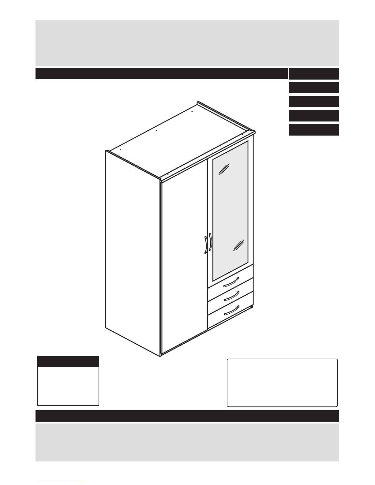
New Hallingford
2 Door 3 Drawer Wardrobe
Dimensions
Width - 99,7cm
Depth - 60,3cm
Height -205,7cm
Issue 7 20-12-2016
Assembly Instructions - Please keep for future reference
2498696
2684321
2599409
2328450
2274951
Tip: To prevent damage,
we recommend that you
build your unit on the
carton(s) it was packed in.
DR899054
Important – Please read these instructions fully before starting assembly
Alternatively, call the Spares Helpline on: 0370 112 1928
For any other queries please contact the Customer Helpline on: 0345 640 2020
If you need help or have damaged or missing parts, please visit: www.argos-support.co.uk
or email: [email protected] (quoting your original order number)
Page 2
1
Note: if required the next
page can be cut out and used
as reference throughout the
assembly. Keep this page with
these instructions for future
reference.
Safety and Care Advice
Important – Please read these instructions fully before starting assembly
• Check you have all the
components and tools listed on
pages 2 and 3.
• Keep children and animals
away from the work area, small
parts could choke if swallowed.
• Make sure you have enough
space to layout the parts before
starting.
• Do not stand or put weight on
the product, this could cause
damage.
• Assemble the item as close
room) as possible.
• Assemble on a soft level
surface to avoid damaging the
• Parts of the assembly will be
easier with 2 people.
• Only clean using a damp cloth
and mild detergent, do no use
bleach or abrasive cleaners.
• From time to time check that
there are no loose screws on
this unit.
• This product should not be
discarded with household
waste. Take to your local
authority waste disposal centre.
Care and maintenance
• Remove all fittings from the
plastic bags and separate them
into their groups.
unit or your floor.
to its final position (in the same
•To reduce the
likelihood of
damaging your
product please
ensure that your
• Dispose of all packaging
carefully and responsibly.
power drill is set on a low torque
setting.
Warning: Only use a manual
screwdriver to attach the hinges.
Instruction video
• This manual is provided with an additional instruction
video. If the icon on the right is displayed at a particular
step in the manual, Follow the link: http://nlink.nu/vid01
Or scan the QR code on the left with your phone.
See page 1 for link
to instruction video!
Page 3
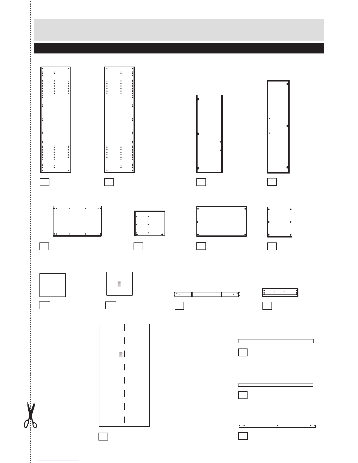
Components - Panels
Please check you have all the panels listed below
2
Right side
(205.6 x 58cm)
2
P2349C
Left side
(205.6 x 58cm)
1
P2349C
Door x 1
(199.2 x 48.8cm)
4
P3724
Top/Bottom x 2
(96.7 x 57.7cm)
5
P1341
Upright small
(47.5 x 57.7cm)
6
P2893
Large horizontal
(96.7 x 57.6cm)
7
P1342
Small horizontal
(47.6 x 57.6cm)
8
P1343
Drawer base x 2
(45.4 x 34.9cm)
BO3395509B
Drawer base x 1
(45.4 x 34.9cm)
BO3395509B60
Drawer wrap x 3
(35 x 46.7 x 10cm)
10
LA186909
Drawer front x 3
(48.8 x 15.7cm)
11
P4315
Plinth front
(96.6 x 14cm)
13
P7334C
Plinth back
(96.6 x 5.4cm)
14
P7335C
Pelmet
(99.9 x 4.5cm)
15
FA247
Foldy back
(199.3 x 98cm)
12
BO339330960/
BO33933160 (CAT2328450)
Mirror door small
(151.2 x 48.8cm)
3
PS3719
For damaged or missing parts, please visit:
www.argos-support.co.uk or email: [email protected]
9a 9b
Page 4

3
Please check you have all the fittings listed below
40mm Screw x 6
Ruler - Use this ruler to help correctly identify the screws
Tools required
A
10mm Fixing screw drawer x 12
E
B
24mm locking screw x 6
H
9mm Srew x 6
C
I
Door/Drawer handle x 5
Q
Note: The quantities below are the correct amount to complete the assembly. In some cases more fittings
may be supplied than are required.
0 5 10 15 20 25 30 35 40 45 50 55 60 65 70 75 80 85 90 95 100
110 115 120 125 130 135 140 145 150 155 160 165 170
105
12.5 mm Screw x 2
F
L-Bracket x 1
15mm Screw x 13
D
Nail x 60
K
15mm Screw x 12
O
Large locking
nut x 22
M
P
Small locking
nut x 6
N
Nail holder x 1
L
G
J
Hinge door x 6
R
Runner x 6
S
T
For damaged or missing parts, please visit:
www.argos-support.co.uk or email: [email protected]
Fittings Drawers
Fittings Carcase
Components - Fittings
Phillips screwdriver
(medium & large)
Flatblade screwdriver
Small
hammer
Ruler/tape
measure
Drill
Eye protection
(when using a
hammer or drill)
5mm Suitable drill bit
GR1975
Hanger rail large x 1
FK1268FK1269
Hinge back x 6
FK1324
FK1012
FK1010
FK1011
24mm locking screw x 22
H
FK1011
FK1301
FK1981
FK1980
FK1400
FK1311
FK1235
Hanger rail support x 2
FK1217
FK1309
Peg x 2
FK1234
FA1515 FK1419
PM1884
PM16951
5mm Suitable drill bit
0 10 20 30 40 50 60 70 80 90 100 110 120 130 140 150
0 1 2 3 4 5 6
Stairs
Piercer
Scissors
(medium)
(small)
Spirit level
Setsquare
U
Drawerbase support x 6
FK1250
V
Wall plug and parkerscrew x 1
ZF99936
20mm Screw x 10
Glue x 1
FA1510
X
Page 5
4
Assembly Instructions
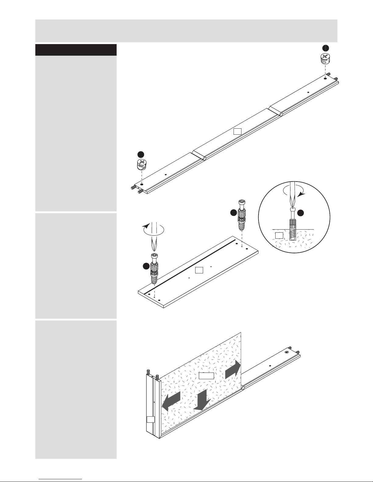
Step 1
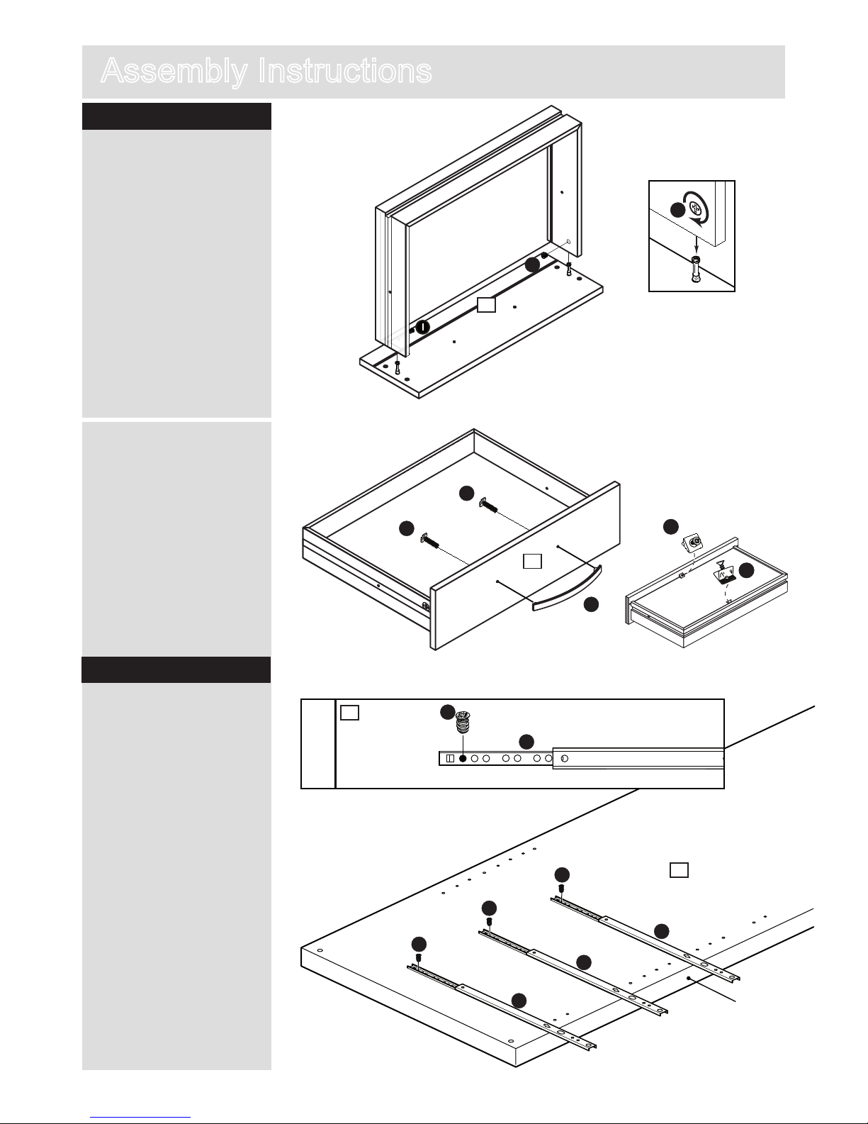
Drawer assembly x 3
a: Insert two small locking
nuts J into drawer wrap
0.
Make sure the ‘arrow’ on
Jis pointing towards the
hole in the edge of 0.
b: Screw 24mm locking
screws H into holes
shown on back of drawer
front !.
Make sure 24mm locking
screws H are tightened
right up against drawer
front !.
c: Slide drawer base 9
into grooves shown on
drawer wrap 0.
H
10
J
J
11
H
H
H
a:
b
10
c:
11
9 a/b
Page 6
5
Assembly Instructions
Step 1 - continued
Attaching runners
d: Turn the drawer wrap
assembly over and push
onto the drawer front !.
Use a phillips or flatblade
screwdriver, that is a good
fit to turn 24mm locking
srew I as far as it will go
- more than 1/2 turn.
H
d
I
e:
11
T
11
B
B
Step 2
a: Slide top of runners R
foreward and fix on right side
2 as shown using 10mm
fixing screw drawer E.
Finished
front edge
a:
R
R
R
R
E
E
E
E
2
2
I
e: Fix drawer handle T
onto drawer front ! using
30mm screw B.
Turn over drawer and slide
drawerbasesupports U
in corner as shown and fix
them, using the attached
screws.
U
U
Page 7
6
Assembly Instructions
b
a:
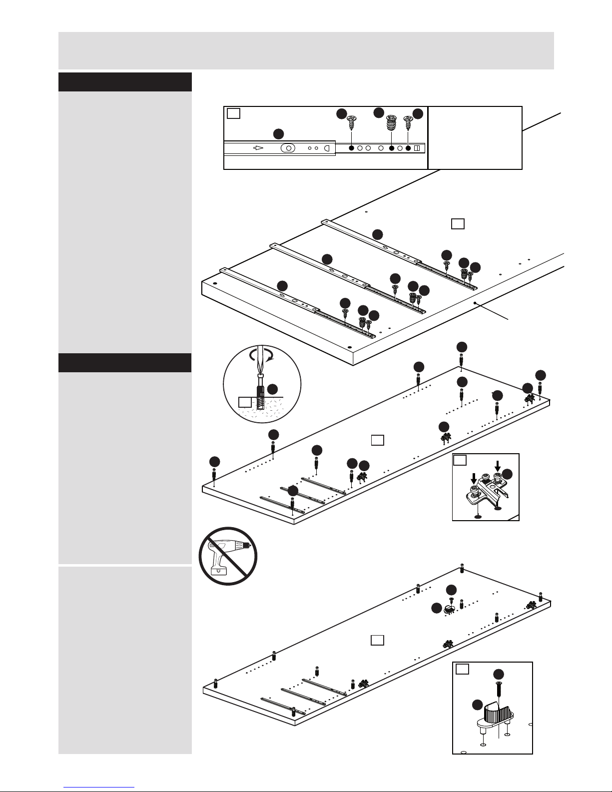
StepStep 2 - continued
b: Slide top of runners R
back.
Fix through 3rd hole of
runner R and pre-drilled
holes of right side 2 using
10mm fixing screw drawer
E.
Fix through 1st and 7th
hole of runners R using
15mm screw O.
Note: there are no predrilled holes for 15mm
screw O.
Repeat a and b on upright
small 6.
Step 3
Insert fittings
a: Screw 24mm locking
screw H into right side
2.
Note: Insert 24mm
locking screw H as far as
shown.
Do not over tighten.
Screw hinge back P onto
right side 2.
H
2
b: Attach hanger rail
support M using 12.5mm
screw F onto right side
2.
2
P
P
P
P
H
H
H
H
H
H
H
H
P
H
M
F
2
2
H
M
2
F
Finished
front edge
R
R
R
E
E
E
3
O
O
O
O
O
O
b
3
R
E
OO
Warning: Do not use an electric screwdriver to attach the
hinges as this can weaken the fixing.
Page 8
7
Assembly Instructions
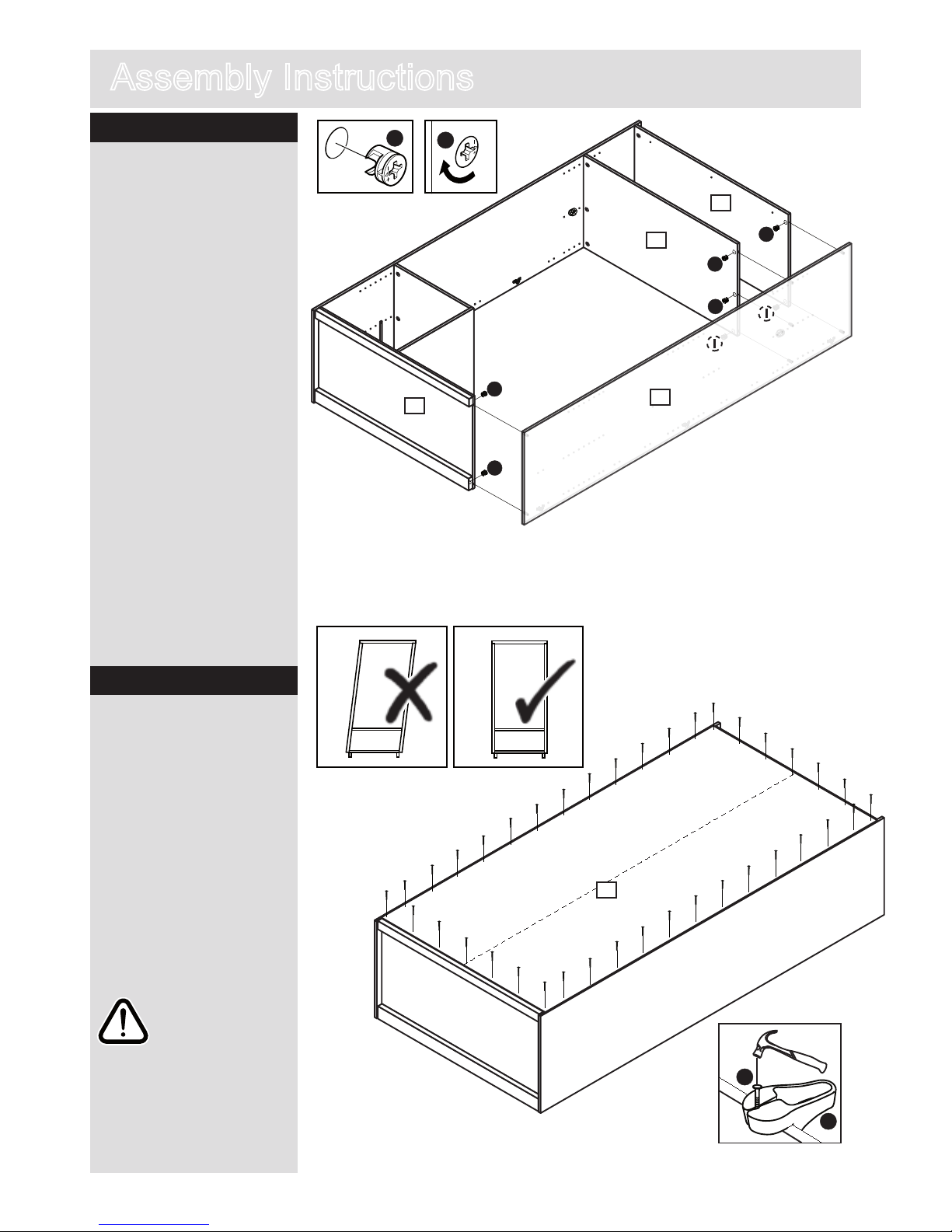
Step 4
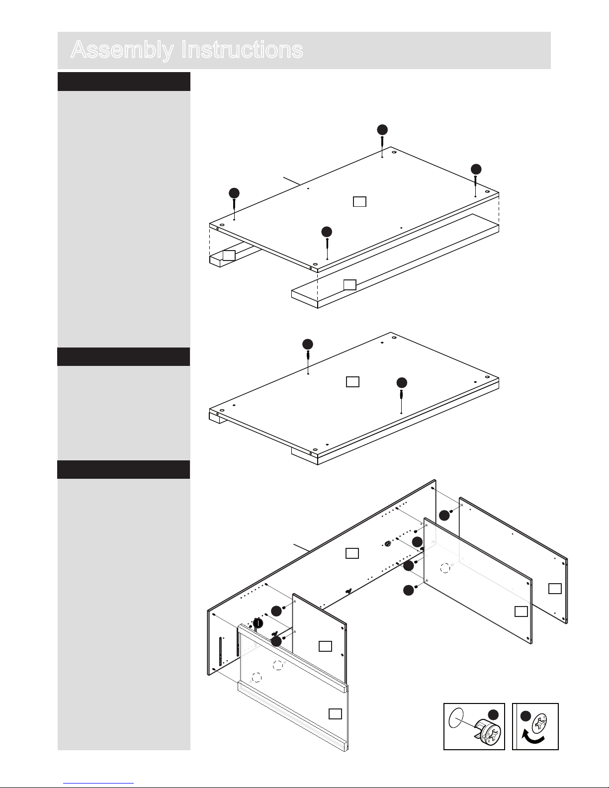
Attaching panels
Attaching plinths
a: Allign the sides of
plinth front # with bottom
5 as shown and attach
using 40mm screw A.
Note: there are no
predrilled holes for
40mm screw A.
Note: top and bottom
panels 5 are identical.
Only prepare one of the
panels at this satge.
This will be the bottom
panel
Repeat with plinth back
$.
A
Step 6
Position bottom 5, small
horizontal 8, large
horizontal 7 and top 5
onto right side 2.
Insert large locking nuts I
into bottom 5, small
horizontal 5, large
horizontal 7 and top 5
where shown.
Use a screwdriver to turn
locking nuts I clockwise
to lock.
Top side
A
A
A
5
Step 5
Insert locking screws
a: Screw 24mm locking
screw H into bottom 5.
Top side
5
M
M
Unfinished
back edge
H
H
I
I
I
I
I
I
I
I
I
I
I
I
2
5
7
5
14
13
Unfinished
back edge
8
Page 9
Step 8
Step 9
I
8
I
I
I
6
5
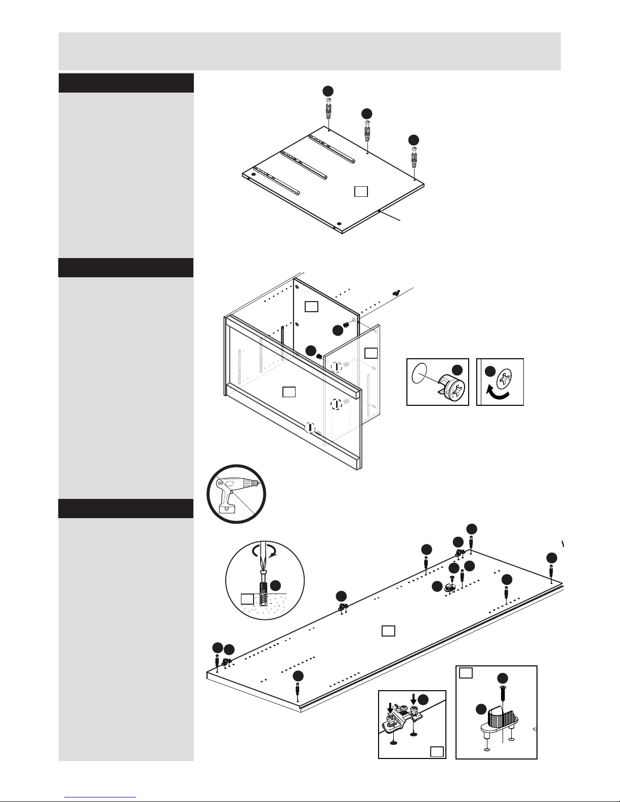
Attaching panels
Two people are needed
here.
Position upright small 6
onto bottom 5 and small
horizontal 8.
Insert two Large locking
nuts I into upright small
6 and small horizontal 8
where shown.
Use a screwdriver to turn
locking nuts I clockwise to
lock.
H
H
H
6
Unfinished
back edge
8
Assembly Instructions
Step 7Step
Insert locking screws
Screw 24mm locking
screw H into upright
small 6.
M
M
I
I
P
P
P
H
H
H
H
H
H
M
F
H
1
1
P
1
Insert fittings
Screw 24mm locking
screw H into left side 1.
Note: Insert 24mm
locking screw H as far
as shown.
Do not over tighten.
Screw hinge back P
onto upright 1.
Attach hanger rail
support M using 12.5mm
screw F onto left side
2.
H
M
1
F
I
Warning: Do not use an electric screwdriver to attach the
hinges as this can weaken the fixing.
Page 10
9
Assembly Instructions
I
Step 10
Step 11
I
I
I
I
I
I
I
M
M
I
I
Attaching panel
Two people are needed
here.
Position left side 1 onto
bottom/top 5 and large
horizontal 7.
Insert large locking nuts I
in top/bottom 5 and large
horiziontal 7.
Use a screwdriver to turn
locking nuts I clockwise
to lock.
Fitting back panel
Attach foldy back @ to back
of wardrobe with the
coloured surface facing the
inside of the unit using nails
K and.
Use nail holder L to hold
the nails K vertical and at
correct distance as you
secure the foldy back @.
Nails K should be spaced
about 150mm apart.
Important:
Cabinet MUST
be ‘square’
when back is
attached.
K
L
1
5
5
7
12
Stand up the unit!
2 people required.
Page 11

See page 1 for link
to instruction video!
10
AssemblyInstructions
SStep 12
A
A
5
D
G
15
Attaching pelment and
L-bracket
Position pelment % onto
top % as shown, fix by
using 40mm screws A.
Position L-Bracket G onto
top 5 as shown, fix by
using 15mm screw D.
Note: there are no
pre-drilled holes for 15mm
screw D.
Use V to fix on the wall,
please see last page for
more information.
Step 13
Inserting hanger rails
Place hanger rail large N
into hanger rail supports
M.
a:
b:
1st small
threaded hole
C
M
S
N
Step 14
Inserting drawers
a: Pull runners out.Slide
drawers onto runners
so they butt up against
back of drawer front. Put
drawer with warning in top
position.
b: Fix through drawer
sides into runners using
9mm screws C.
Q
4
T
B
B
D
D
D
Q
Q
Q
Step 15
Fitting hinges to doors
Fix three hinge door Q
to door 4 and mirror
door small 3 using
15mm screws D.
Attach door handles T
using 30mm screws B.
4
3
3
V
V
D
D
Warning: Do not use an electric screwdriver to attach the
hinges as this can weaken the fixing.
Page 12
See page 1 for link
to instruction video!
b:
Q
Q
P
11
Assembly Instructions
a:
SNAP!
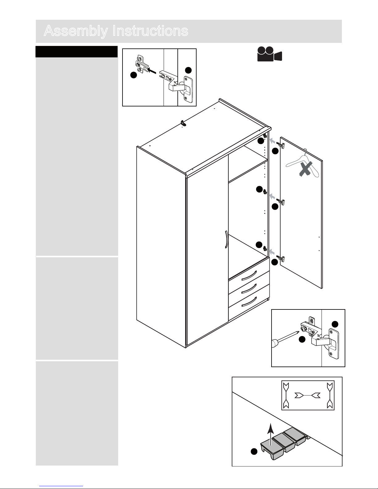
Step 16
Hanging doors
a: With help, slot hinge
door Q onto hinge back
P.
b: Tighten screw shown
to lock hinges in position.
Repeat a and b for other
door.
See ‘Hinge adjustment’
in step 17 if the doors
need adjusting.
c: Before adjusting the
doors, use a spirit level to
check if the base of this
unit is level front-to-back
and side-to-side in the
three positions shown.
Use pegs S to square
your unit. Knock peg S in,
as far as you require,
under the ends of the unit
and then snap off flush
with the panel.
c:
Q
P
S
Q
P
Q
P
Q
P
Page 13
12
AssemblyInstructions
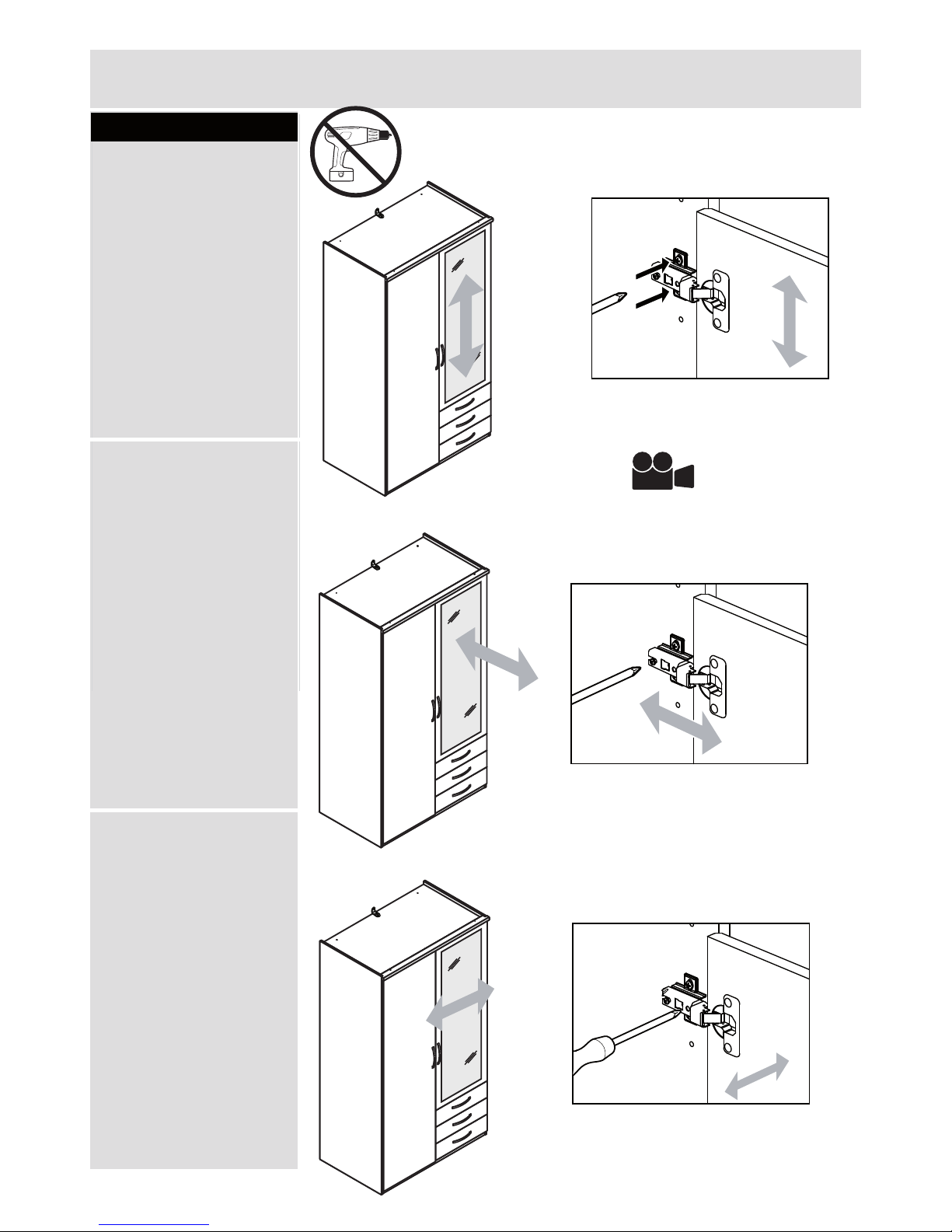
Step 17
Hinge adjustment
a: To move doors up
or down: loosen screws
shown and move doors
to suit.
Once doors are aligned,
re-tighten.
b: To move doors in
or out: loosen screw
shown and move doors
to suit.
Re-tighten screws.
a:
b:
c:
c: To move doors left
or right: loosen screw
shown and move doors
to suit.
Re-tighten screws.
Warning: Do not use an electric screwdriver to attach the
hinges as this can weaken the fixing.
See page 1 for link
to instruction video!
Page 14
13
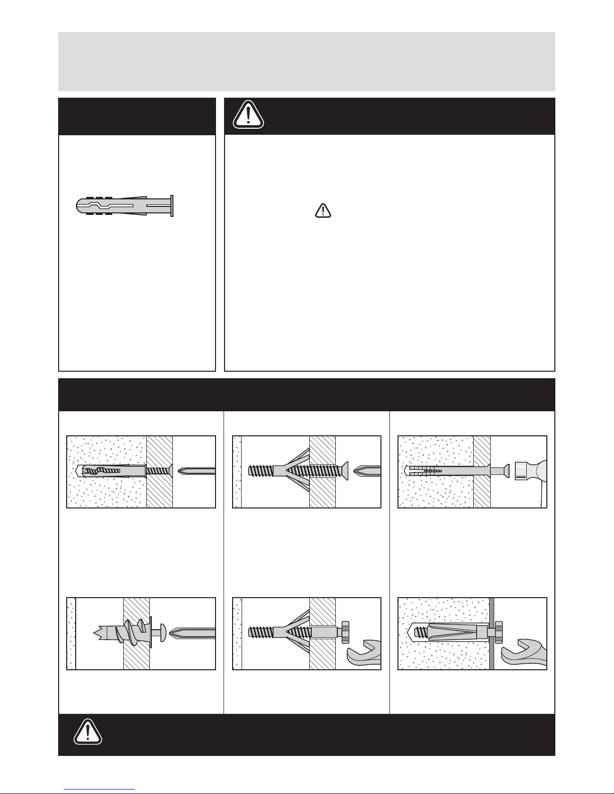
A Guide to - Wall Mounting & Fixings
Important note:
Types of walls
Care &
Maintenance
No.1 “General Purpose” wall plug
No.6 “Shield Anchor” wall plug
Heavy loads
No.3 “Cavity Fixing” wall plug
No.4 “Cavity Fixing-Heavy Duty”
wall plug
No.5 “Hammer Fixing” wall plug
No.2 “Plasterboard” wall plug
Generally aerated blocks should not
be used to support heavy loads, use
a specialist fitting in this case. For light
loads, general purpose wall plugs can
be used.
For use with heavier loads such as TV
& HiFi speakers and satelite dishes etc.
For use with plasterboard partitions or
hollow wooden doors.
For use when fitting or supporting
heavy loads such as shelving, wall
cabinets and coat racks.
For use with walls stuck with
plasterboard. The hamemr fixing allows
it to be fixed to the wall rather than the
plasterboard. Always check the fixing
is secure to the retaining wall.
For use when attaching light loads on
to plasterboard partitions.
Safety: Always check the fitting
and location to ensure your safety
in and around the home.
Fitting: From time to time check
the fitting to ensure the wall plugs
or screws do not become loose.
You can use one of the following types of wall plug if your walls are made
of brick, breeze block, concrete, stone or wood.
Important: When drilling into walls always
check that there are no hidden wires or pipes etc.
Hints:
1: General rule: Always use a larger screw and wall plug
if you are not sure.
2: Ensure you use the recommended drill bit to match the wall
plug and hole size.
3: Ensure you drill the hole horizontally, do not force the drill or
enlarge the hole.
4: Take extra care when drilling high walls, ceilings and ceramic
tiles. Ensure wall plugs are inserted beyond the thickness of
the ceramic tiles to avoid the tiles splitting or cracking.
5: Ensure wall plugs are well fitted and are a tight fit in the
drilled hole.
If plastic wall plugs
are supplied with your
product:
Make sure that the screws and wall plugs being used
are suitable for supporting your unit. Consult a qualified
tradesperson if you are unsure.
- these are only suitable for
use in masonry walls.
If you are in any doubt about
the correct wall plugs for
your wall, seek professional
advice.
Failure of the product due to
using incorrect fixings is the
responsibility of the installer.
 Loading...