

Page 1
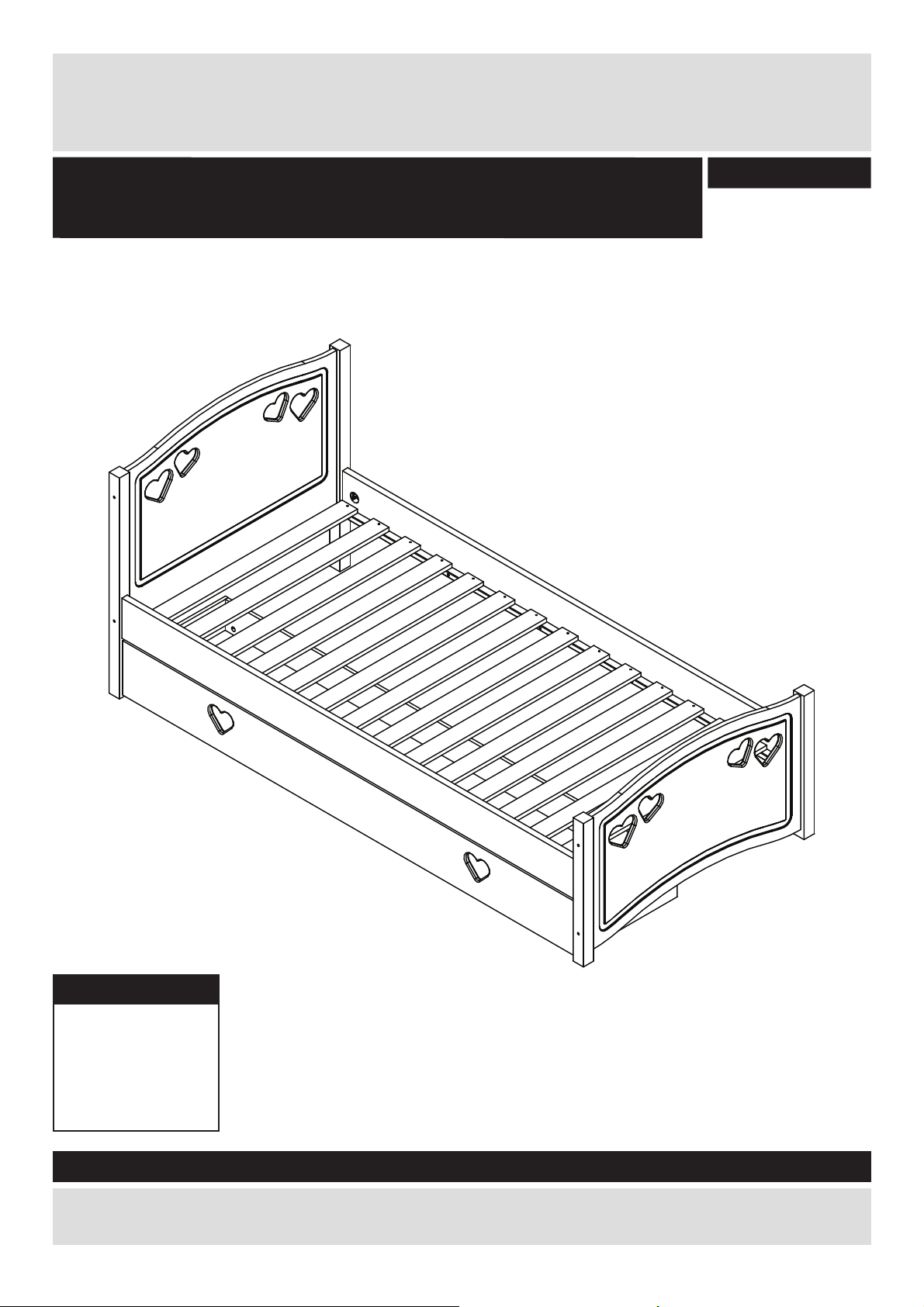
Mia Single bed Hearts & Drw. White
IMPORTANT! KEEP FOR FUTURE
REFERENCE
2572141
Dimensions
Length - 198,3cm
Depth - 96,5cm
Height - 85,5cm
Weight - 42,5kg
Important – Please read these instructions fully before starting assembly
If you need help or have damaged or missing parts, call the Customer Helpline:
0045 7668 8055 or e-mail: order@fl exa.dk
Issue 3 - 11/01/21
Page 2
Safety and Care AdviceSafety and Care Advice
Important – Please read these instructions
fully before starting assembly
80-27901-20 Singlebed
IMPORTANT! KEEP FOR FUTURE REFERENCE
PLEASE DISPOSE OF PACKAGING MATERIAL.
PLASTIC BAGS CAN BE DANGEROUS TO YOUNG CHILDREN
WARNING! Not suitable for children under 4 years.
WARNING! Do not place this child’s bed near heat sources, windows and other furniture.
WARNING! Do not use this child’s bed if any of the parts are broken, torn or missing.
WARNING! Once assembled, this bed must not be disassembled. Screws must not be removed once inserted.
This child’s bed is to be used with a 1900mm x 900mm ma ress.
Suitable for over 4 years old to adults.
All assembly Įxings should be checked periodically and re-
Children are likely to play, bounce, jump and climb on beds, therefore the child’s bed should not
be placed too close to other furniture or windows, bl
placed either
Any addi
ght to any wall or have a gap of 300mm between the wall and the side of the bed.
Always place the side of the bed with the safety rail against a wall.
onal or replacement parts should only be obtained from the manufacturer or distributor.
This product complies to standard BS8509: 2008+A1:2011
ind cords, curtain pulls or other strings or cords, and should be
ghtened where necessary.
CARE AND MAINTENANCE
To clean use a damp cloth, avoiding the use of strong detergents or abrasives.
1
Page 3

Safety and Care Advice
Important – Please read these instructions
fully before starting assembly
• Check you have all the
components and tools listed on
pages 2 and 3.
• Remove all fi ttings from the
plastic bags and separate them
into their groups.
• During assembly children
should be kept away from the
product due to possible risk of
injury.
• Make sure you have enough
space to lay out the parts before
starting.
Care and maintenance
• Only clean using a damp cloth
and mild detergent, do no use
bleach or abrasive cleaners.
• Do not stand or put weight on
the product, this could cause
damage.
• Assemble the item as close
to its fi nal position (in the same
room) as possible.
• Assemble on a soft level
surface to avoid damaging the
unit or your fl oor.
• Parts of the assembly will be
easier with 2 people.
• From time to time check that
there are no loose screws on
this unit.
• We do not
recommend the
use of power
drill/drivers for
inserting screws,
as this could
damage the unit. Only use hand
screwdrivers.
• Dispose of all packaging
carefully and responsibly.
• Assembly to be carried out by
a competent adult only.
• This product should not be
discarded with household waste.
Take to your local authority
waste disposal centre.
2
Page 4
If you have damaged or missing components,
Components - Parts
call the Customer Helpline:
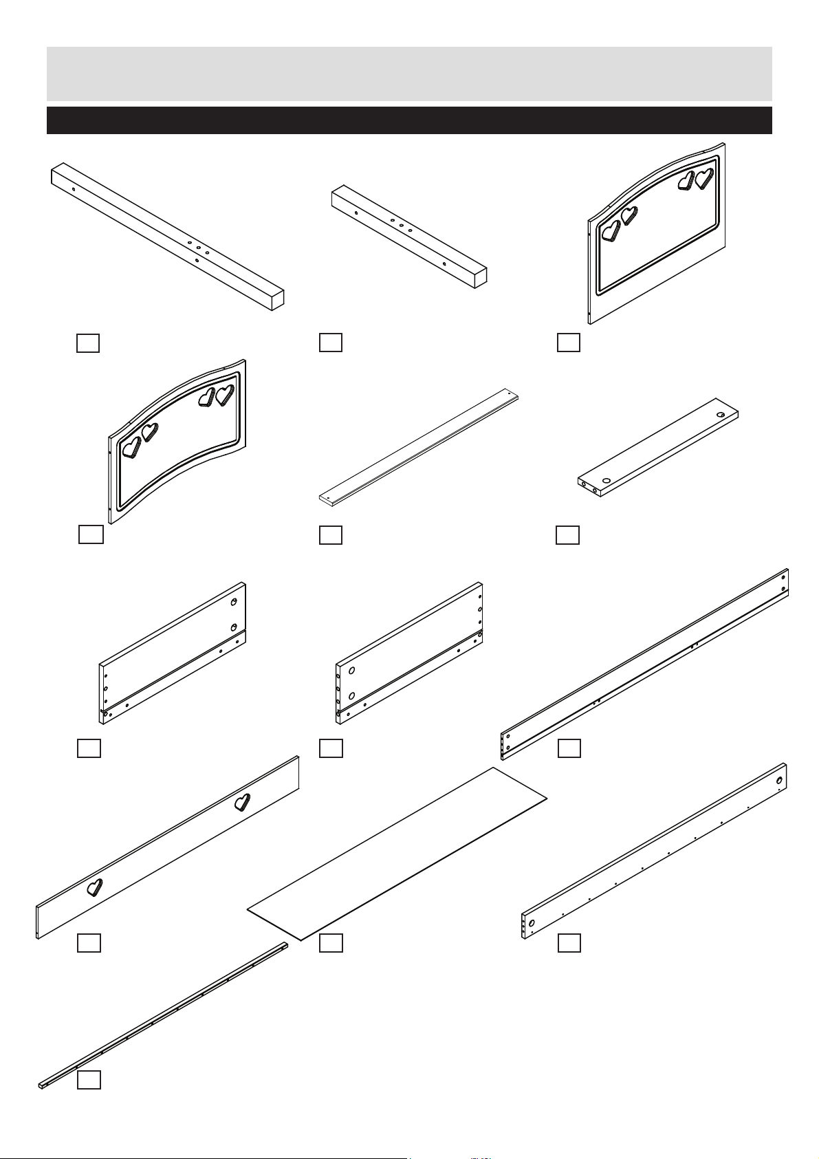
Please check you have all the parts listed below
0045 7668 8055
Leg x2 (80,0x4,3x4,3cm)
1
No. 12-04308001-20
End panel x1
4
(87,9x48,4x1,6cm)
No. 4301-1608791-40
2
Leg x2 (51,9x4,3x4,3cm)
No. 12-04305191-20
Slat x15 (89,7x6,5x1,5cm)
5
No. 12-01508971
End panel x1
3
(87,9x64,0x1,6cm)
No. 4301-1608792-40
Base list x2
6
(40,0x6,5x1,5cm)
No. 12-01504001
Drawer side Right x1
7 8
(41,3x14,5x1,2cm)
No. 4301-1204131-40 No. 4301-1204132-40 No. 4301-1218651-40
Drawer front x1
10
(189,1x19,7x1,6cm)
No. 4301-1618911-40
List x2 (187,0x2,6x2,0cm)
13
No. 12-02018703
Drawer side Left x1
(41,3x14,5x1,2cm)
Drawer base x1
11 12
(187,6x41,1x0,3cm)
No. 4309-0318761 No. 4301-2218971-40
Drawer back x1
9
(186,5x14,5x1,2cm)
Bedside x2
(189,7x14,5x2,2cm)
3
Page 5
Components - Fittings
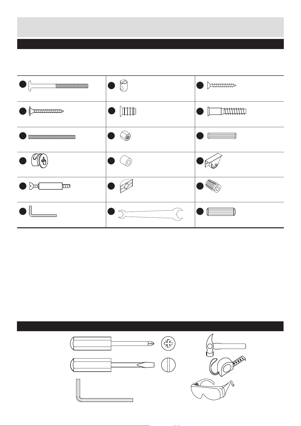
Please check you have all the fi ttings listed below
Note: The quantities below are the correct amount to complete the assembly. In some cases more fi ttings
may be supplied than are required.
No. 3913-06080
A
M6x80mm Connecting bolt x8
No. 3903-40035
D
No. 3922-060131
B
M6 ø10x13mm Barrel nut x8
No. 3907-61011
E
C
4,0x30mm Chipboard screw x30
F
No. 3901-40030
No. 3908-70040
4,0x35mm Chipboard screw x2 6,1x11mm Euro screw x8 7,0x40mm Confi rmat screw x20
No. 3921-06070
G
M6x70mm Threaded pin x4
No. 3933-15010
J
ø15x9,5mm Minfi x cam x12
No. 4020-007
M
ø7x34mm Minifi x bolt x12
No. 4033-010
P
6mm Hexagon key x1
H
M6x10mm Nut x4
K
ø12/ø6,5x11mm Spacer x2
N
ø35x8,6x15mm Bracket x4
Q
13/10 Cresent wrench x1
No. 3927-000066 No. 3930-08040
i
8x40mm Dowel x8
No. 3940-000111
No. 4003-003
L
ø35mm Castor x4
No. 4024-005
No. 4028-021
O
M6/ø12x20mm Threaded bush x4
No. 4033-016
No. 3930-08030
R
8x30mm Dowel x12
Tools required
Phillips
screwdriver
(medium)
Flatblade
screwdriver
(medium)
Allen key
4mm incl.
No. 4033-002
Small
hammer
Ruler/tape
measure
Eye protection
(when using a
hammer or glue)
4
Page 6
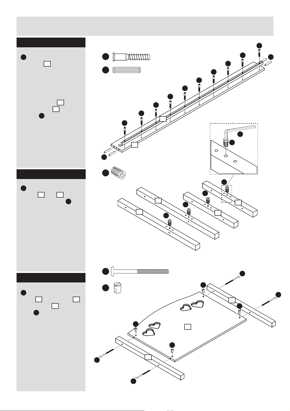
Assembly Instructions
Step 1
Insert the 40mm dowels
i
into the holes in
12
bedsides
.
It may be necessary
to tap the dowels in
very gently with a small
hammer.
13
12
to
using
Attach the lists
the bedsides
screws
F
Step 2
Insert threaded bushes
O
into the shown holes
1
in legs
the 6mm allen key
and 2 with
P
.
i
O
F
F
i
F
12
F
1
NB!
F
F
F
F
F
13
O
O
1
O
O
2
F
F
P
O
2
i
Step 3
Insert four barrel nuts
B
into the holes in end
3
panel
to end panel
bolts
Note the placement
of the legs - grooves
in the end panel are
facing the side with
the 3 holes for the
bedsides.
5
. Attach legs 1
3
using
A
.
A
B
B
B
A
A
1
3
B
A
A
1
B
Page 7
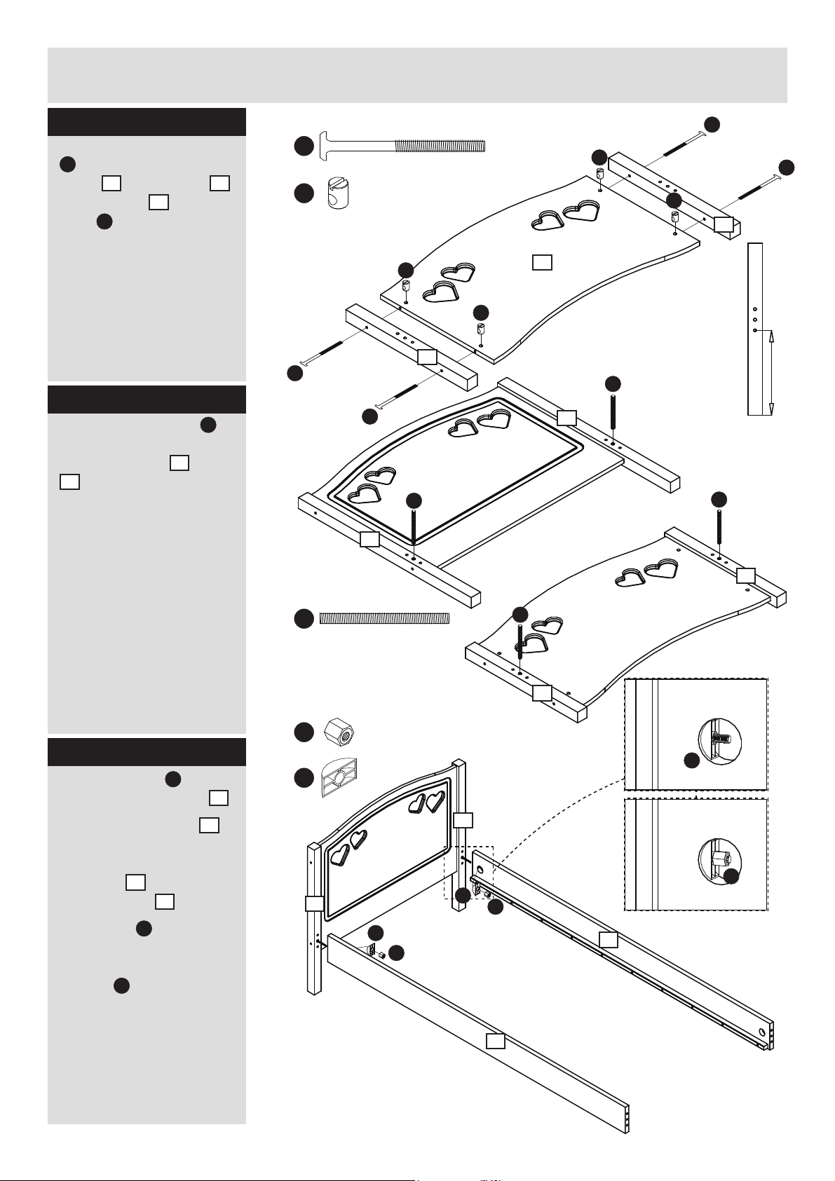
Assembly Instructions
Step 4
Insert four barrel nuts
B
into the holes in end
4
panel
to end panel
bolts
. Attach legs 2
4
using
A
.
Note the placement
of the legs - grooves
in the end panel are
facing the opposite
direction of the 3 holes
for the bedsides.
Step 5
G
1
and
Insert threaded pins
into the threaded bushes
installed in legs
2
.
A
A
B
B
B
2
A
4
B
B
2
G
A
256 mm
A
G
1
Down
G
Step 6
N
Insert brackets
the holes in bedsides
Attach the bedsides
to the headboard by
inserting the dowels in
bedsides
12
holes on legs
Insert nuts
H
holes in bedsides and
tighten the nuts with the
wrench
Q
into
into the
1
.
into the
12
12
1
2
G
G
2
H
N
N
.
1
N
H
1
H
N
H
12
Don’t overtighten.
12
6
Page 8
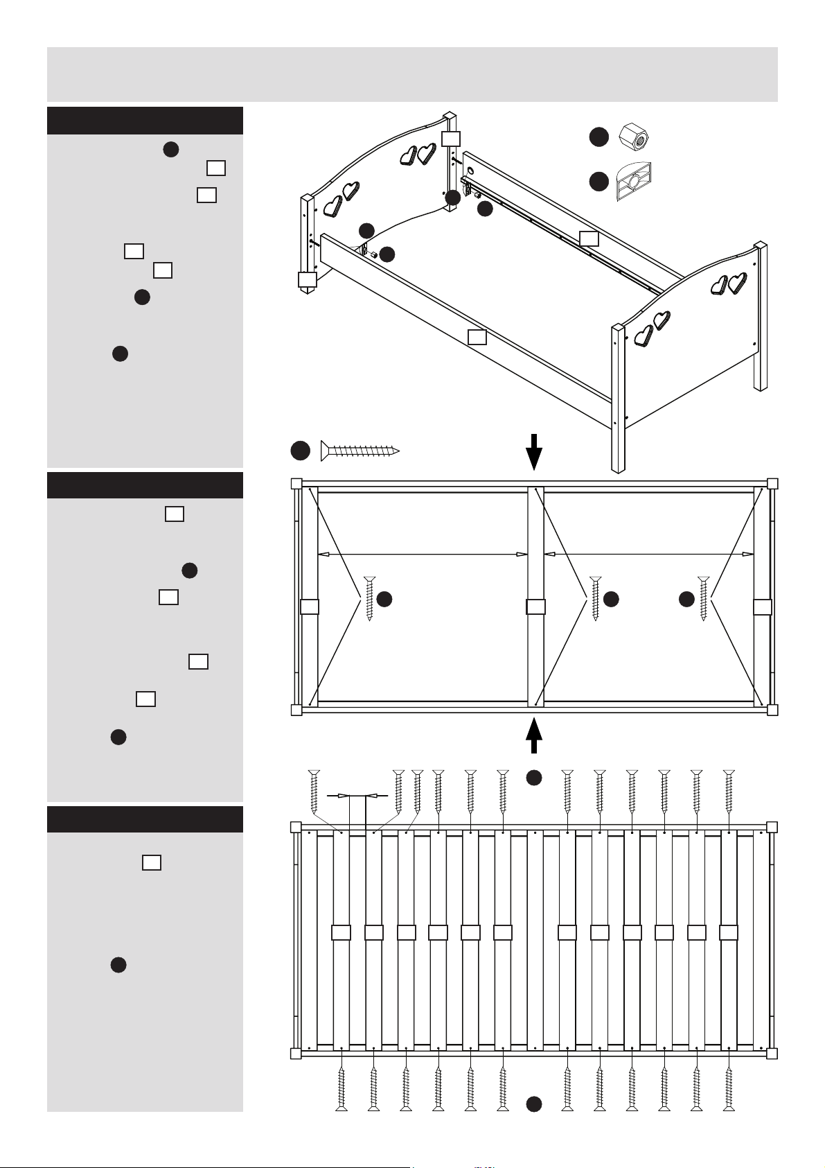
Assembly Instructions
Step 7
Insert brackets N into
12
12
.
N
H
2
C
the holes in bedsides
Attach the bedsides
to the headboard by
inserting the dowels in
12
bedsides
holes on legs
Insert nuts
into the
2
.
H
into the
holes in bedsides and
tighten the nuts with the
wrench
Q
Don’t overtighten.
2
H
N
N
H
12
12
Step 8
5
to the
5
in the
C
5
in the
12
.
Place two slats
ends of the bed, against
the legs. Fasten with four
chipboard screws
Place one slat
middle of the bed. Follow
the measurements.
Push the bedsides
together whilst attaching
middle slat
bed with two chipboard
C
screws
.
Step 9
Position the remaining
5
twelve slats
bed with an approximate
distance of 66-67 mm
between each.
Fasten each slat with two
screws
C
in the
851 mm
C C C
66-67 mm
5 55 55 55 55 55 5
55
5
C
851 mm
5
C
7
Page 9
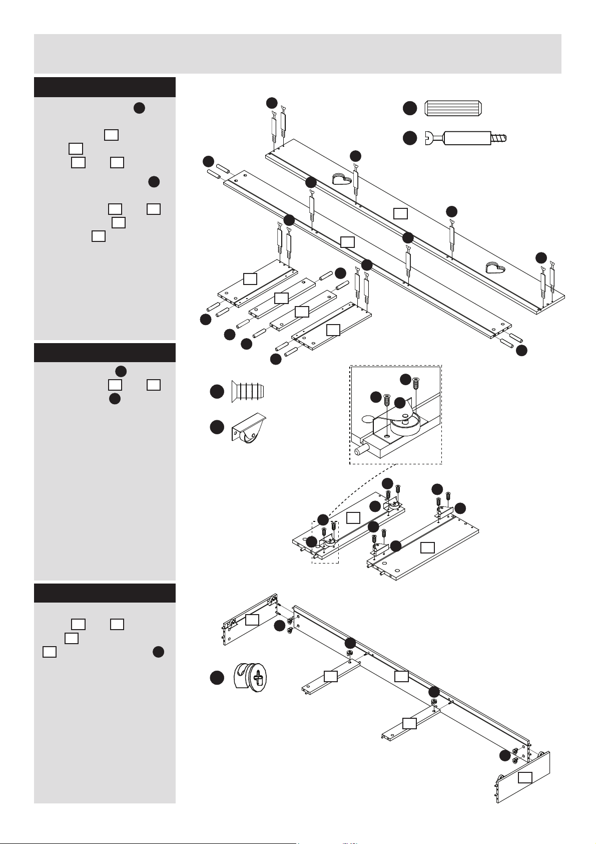
Assembly Instructions
Step 10
Insert minifi x bolts M
into the shown holes in
10
drawer front
9
back
sides
and drawer
7
and 8.
, drawer
Insert 30mm dowels
into the shown holes in
7
drawer sides
and
, drawer back 9 and
6
base lists
.
Step 11
L
Attach castors
drawer sides
using screws
to the
7
and 8
E
.
R
R
8
R
R
E
M
8
R
R
R
NB!
M
M
M
M
9
M
R
6
6
7
10
M
E
E
L
M
M
R
Step 12
Assemble the drawer
7
sides
lists
9
and 8, base
6
and drawer back
using minifi x cams J.
L
E
L
E
L
7
J
J
8
E
L
J
6
9
E
L
7
J
6
J
8
8
Page 10
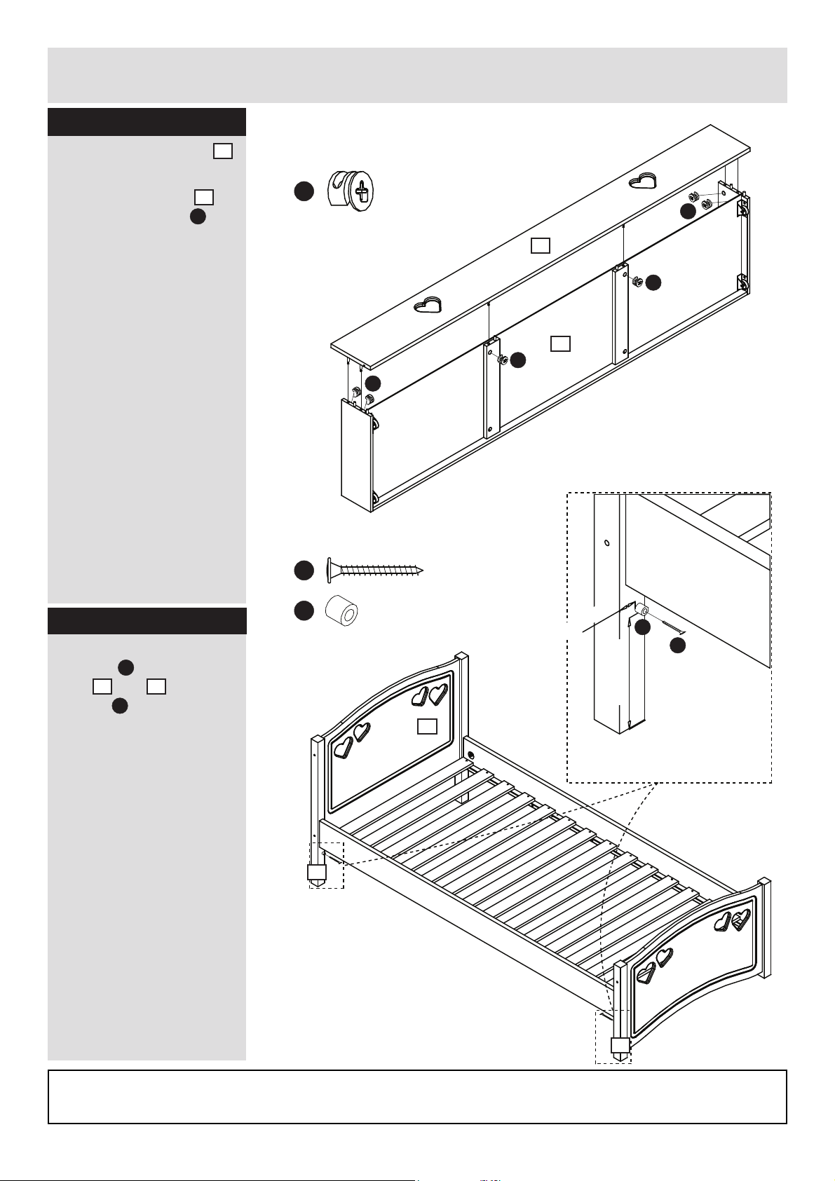
Assembly Instructions
Step 13
Slide the drawer base 11
into the drawer.
Attach drawer front
using minifi x cams
10
J
.
J
J
J
10
J
11
J
Step 14
Attach drawer stop
K
spacers
legs
screws
measurements.
Assembly is complete.
to the
1
and 2 using
D
. Follow the
D
K
26,5 mm
K
D
170 mm
11
1
If you need help or have damaged or missing parts,
call the Customer Helpline: 0045 7668 8055
E-mail: order@fl exa.dk
Ref.no. 44-01708-20 C Stand: 110121 Page 10 (80-27901-20)
9
2
Page 11

 Loading...