

Page 1
MADE IN
BRITAIN
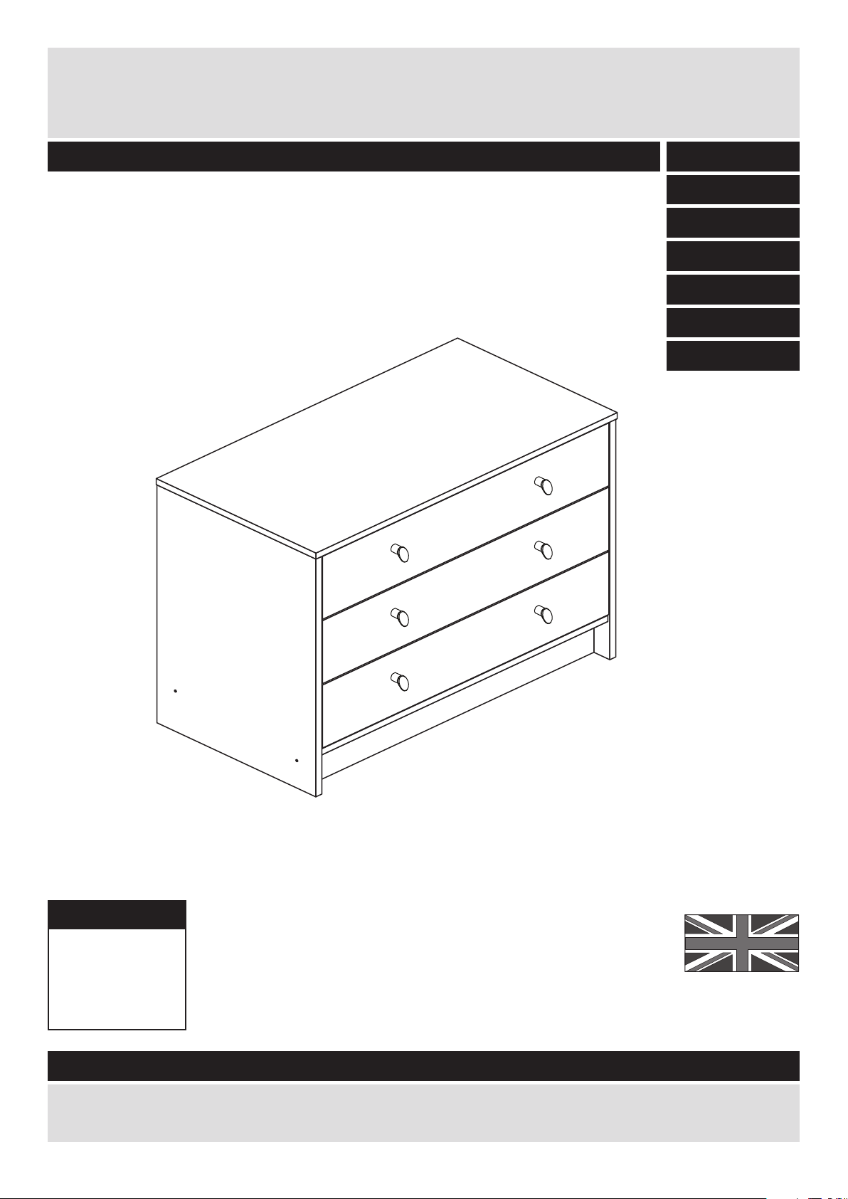
Dimensions
Width - 75cm
Depth - 39.5cm
Height - 60.5cm
Malibu - 3 Drawer Wide Chest
Assembly Instructions - Please keep for future reference
If you need help or have damaged or missing parts, call the Customer Helpline: 08456 400800
Issue 5 - 23/10/14
Important - Please read these instructions fully before starting assembly
275/8903
244/8914
274/4027
244/9061
268/4905
248/3632
266/8859
Page 2

Safety and Care Advice
Important - Please read these instructions fully before starting assembly
• Warning: This unit weighs
approximately 20.5kgs.
Please lift with care.
• Check you have all the
components and tools listed on
pages 2 and 3.
• Remove all fittings from the
plastic bags and separate them
into their groups.
• Keep children and animals
away from the work area, small
parts could choke if swallowed.
• Parts of the assembly will be
easier with 2 people.
• Make sure you have enough
space to layout the parts before
starting.
• Do not stand or put weight on
the product, this could cause
damage.
• Assemble the item as close to
its final position (in the same
room) as possible.
• Assemble on a soft level
surface to avoid damaging the
unit or your floor (use opened
out unit carton).
1
Care and maintenance
• Only clean using a damp cloth
and mild detergent, do no use
bleach or abrasive cleaners.
• From time to time check that
there are no loose screws on
this unit.
• This product should not be
discarded with household
waste. Take to your local
authority waste disposal centre.
Note: If required the next page
can be cut out and used as
reference throughout the
assembly. Keep this page with
these instructions for future
reference.
• We do not
recommend the
use of power
drill/drivers for
inserting screws,
as this could damage the unit.
Only use hand screwdrivers.
• Safety note: It is
recommended that this unit is
secured to a wall using the
bracket supplied.
• Dispose of all packaging
carefully and responsibly.
Page 3
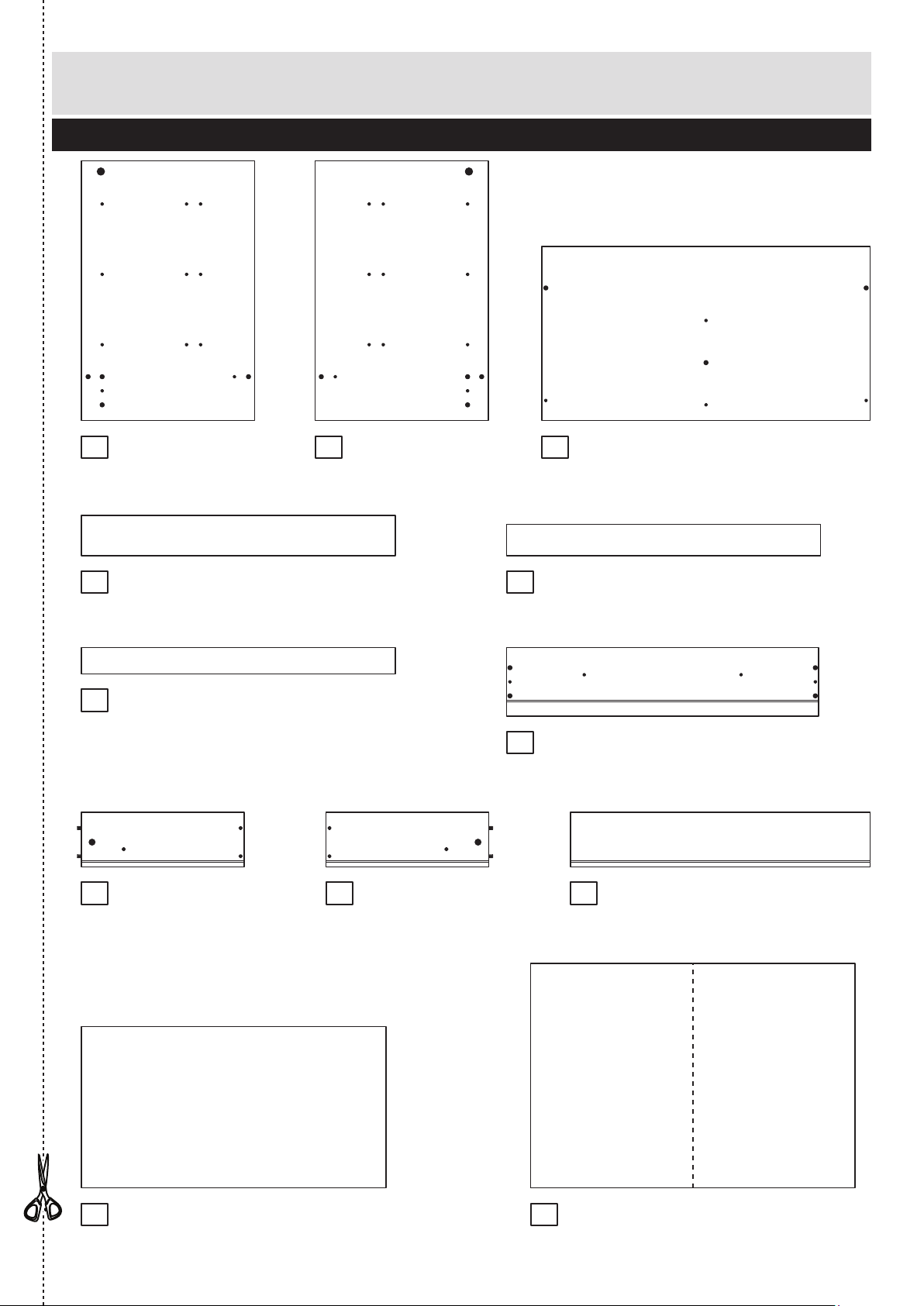
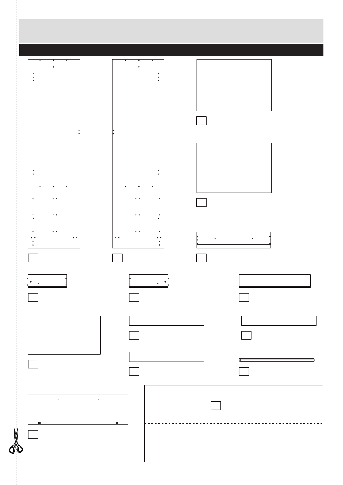
Components - Panels
Please check you have all the panels listed below
2
If you have damaged or missing components, call the
Customer Helpline: 08456 400800 quoting the reference
numbers below
1 2
7
4
Left Side (D2821A)
(591 x 394mm)
Left Drawer
Side (W370-124LH)
(370 x 124mm) x 3
Right Drawer
Side (W370-124RH)
(370 x 124mm) x 3
Right Side (D2822A)
(591 x 394mm)
5
8 9
Top (D2774B)
(747 x 396mm)
Drawer Front (D2783A)
(710 x 156mm) x 3
Back Rail (D2779A)
(714 x 60mm)
Plinth (D2778A)
(714 x 92mm)
Rail (D2780A)
(714 x 72mm)
6
10
11
Drawer Back (W682-124)
(682 x 124mm) x 3
Drawer Base (T693-367)
(693 x 367mm) x 3
Back (X511-738)
(511 x 738mm)
12
3
Page 4
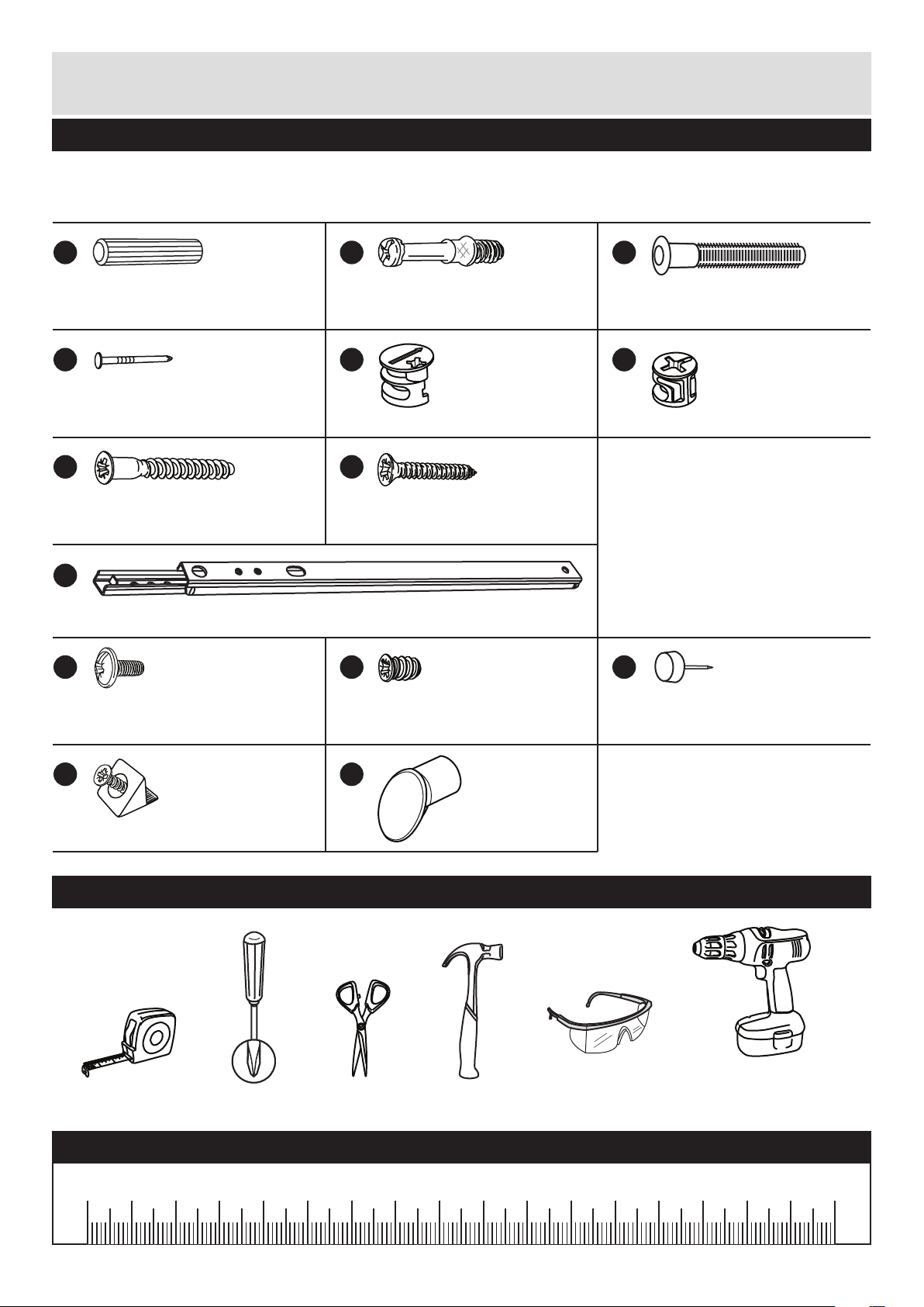
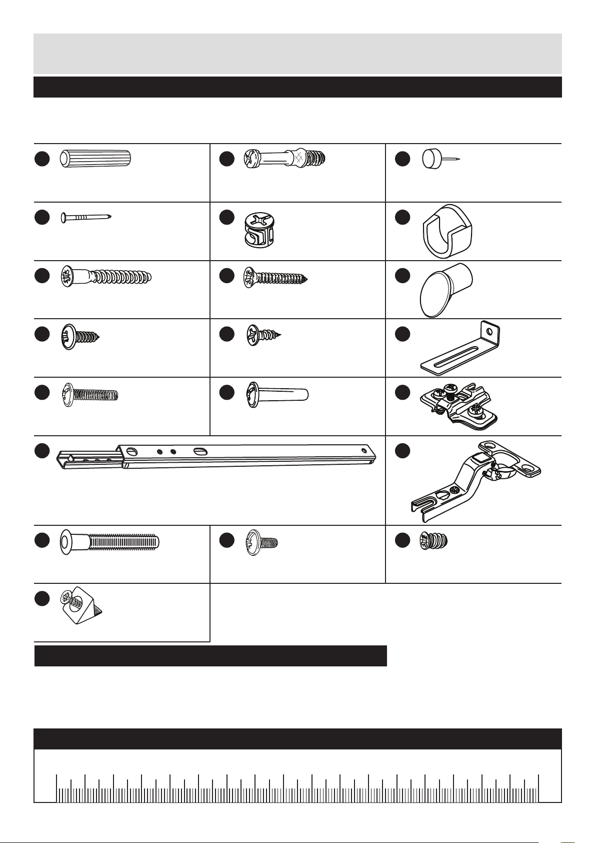
Please check you have all the fittings listed below
Tools required
3
Components - Fittings
If you have damaged or missing components, call the
Customer Helpline: 08456 400800 quoting the reference
numbers below
Rule Scissors Hammer
Eye protection
(when using a
hammer or drill)
Cross-head
screwdriver
Ruler - Use this ruler to help correctly identify the screws
mm 10 20 30 40 50 60 70 80 90 100 110 120 130 140 150 160 170
Electric drill
(only use when
drilling into walls)
Note: The quantities below are the correct amount to complete the assembly. In some cases
more fittings may be supplied than are required.
A
Wooden dowel (F22) x 10
B
Metal dowel (F901) x 8
C
D
Large locking
nut (F900) x 2
E
Small locking
nut (F3) x 6
F
G
40mm Screw (F910) x 4
H
25mm Screw (F50) x 6
I
Nail (F51) x 16
Knock-in Peg (F171GY) x 12
Handle (F631) x 6
N
L
Plastic Nail (F91) x 4
J
9mm Screw (F74) x 6
K
9mm Screw (F73) x 12
M
Wedgefix (F639) x 12
Drawer runner (F1004) x 6
Page 5
Assembly Instructions
4
If you have damaged or missing components, call the
Customer Helpline: 08456 400800 quoting the reference
numbers below
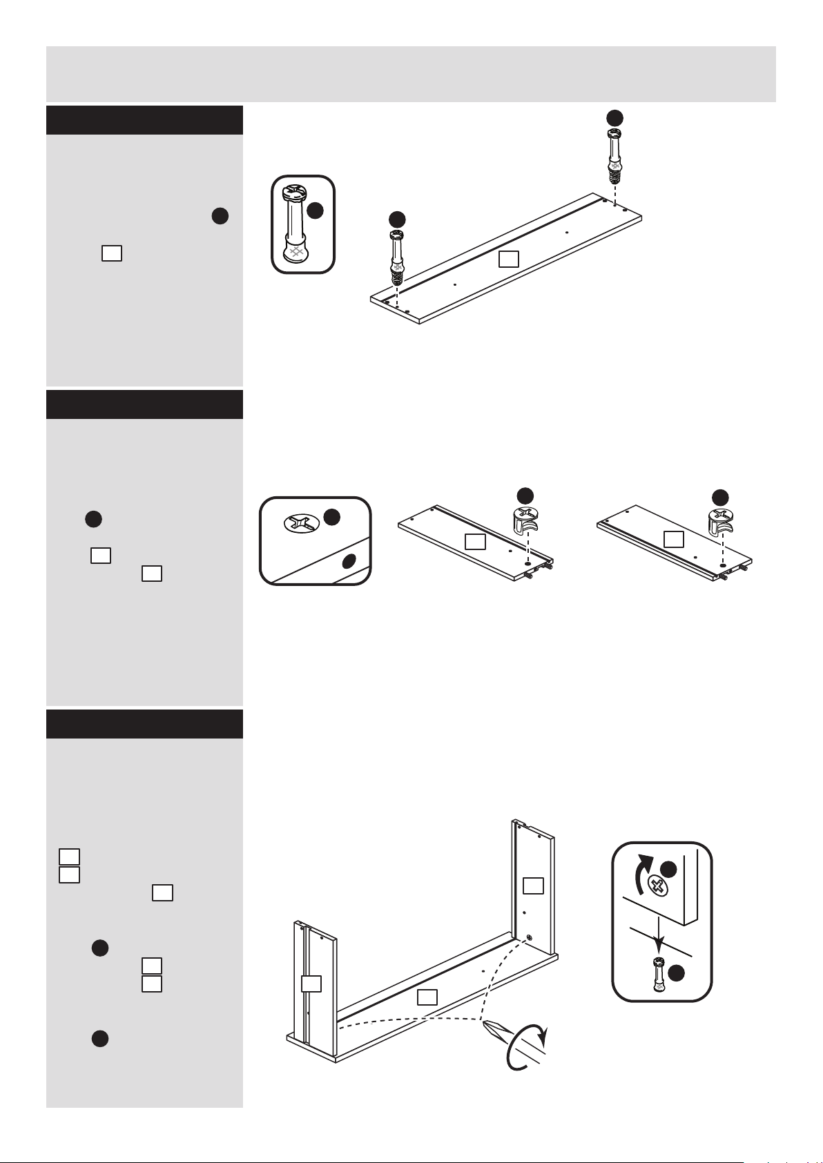
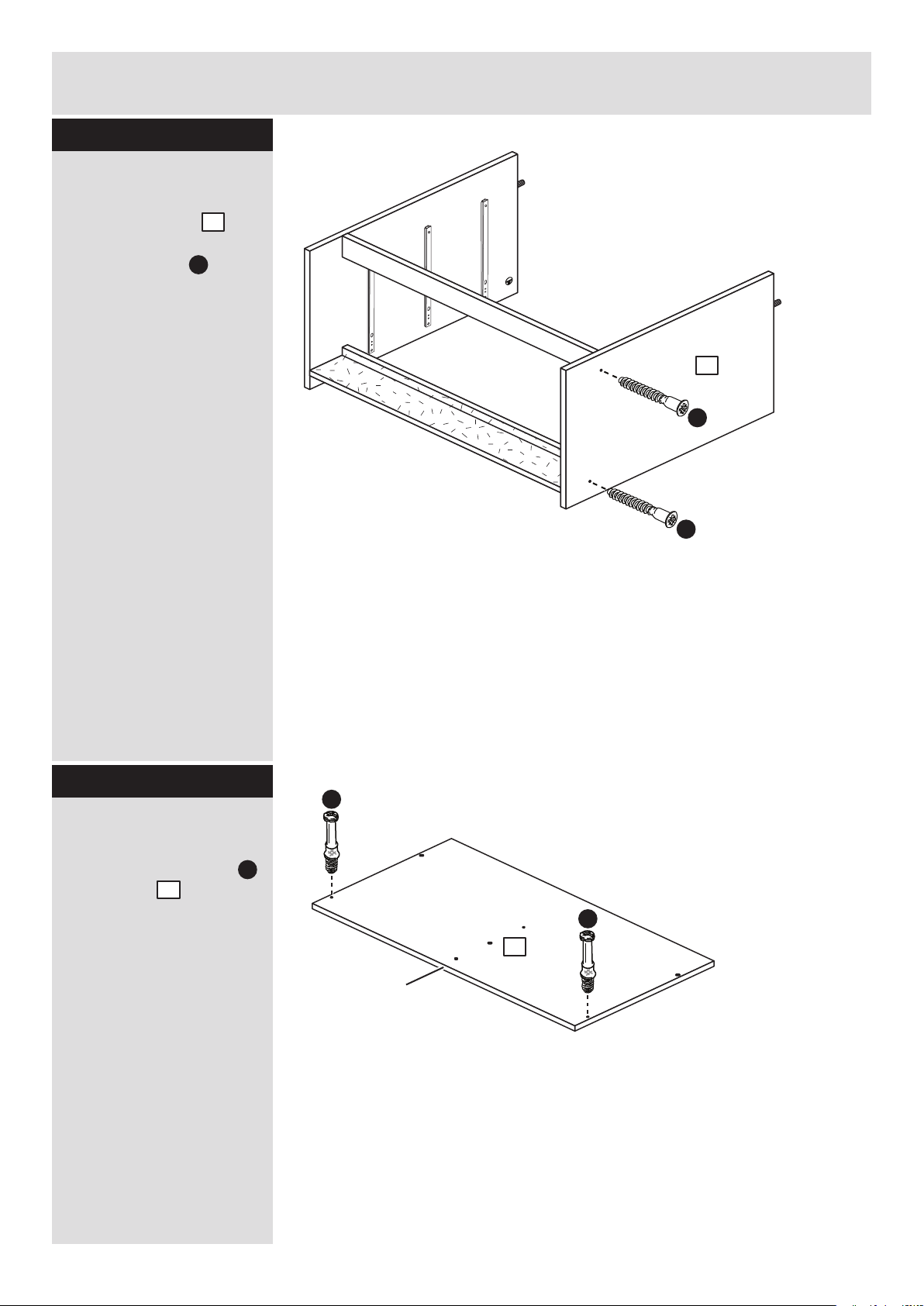
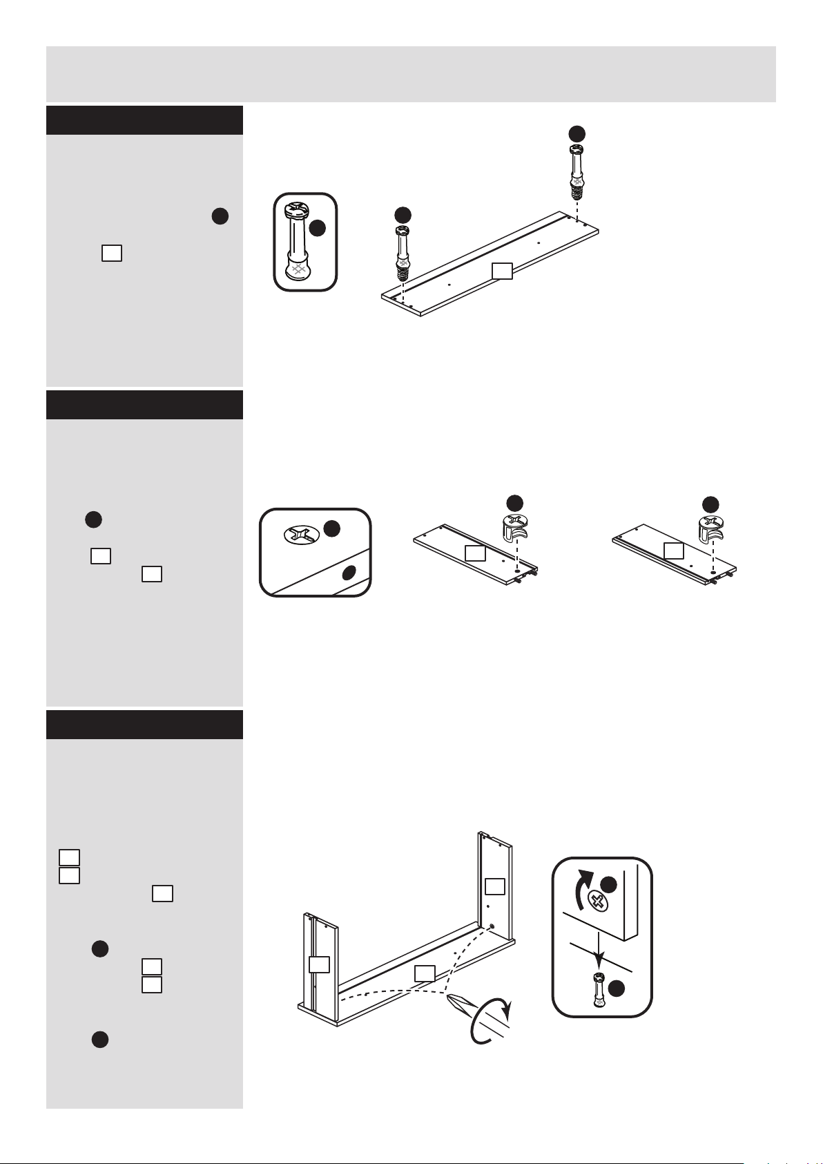
Step 1
Step 2
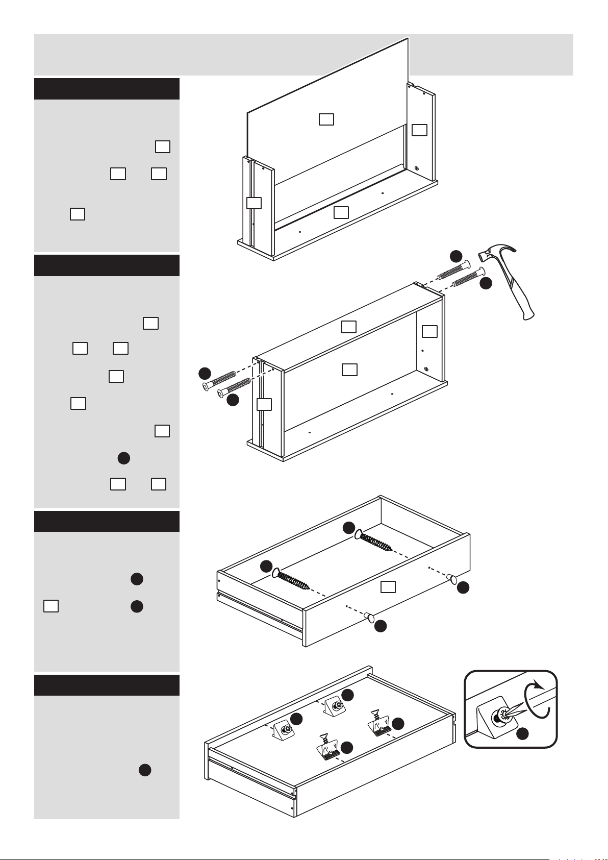
Prepare the 3 drawer
fronts
Screw 2 metal dowels
into each of the drawer
fronts .
Note: Tighten the metal
dowels up fully against
the panels.
B
7
Prepare the drawer
sides
Insert a small locking
nut into the hole
shown on the left drawer
side and the right
drawer side .
Note: The arrow on the
locking nut must point
towards the hole in the
edge of the panel.
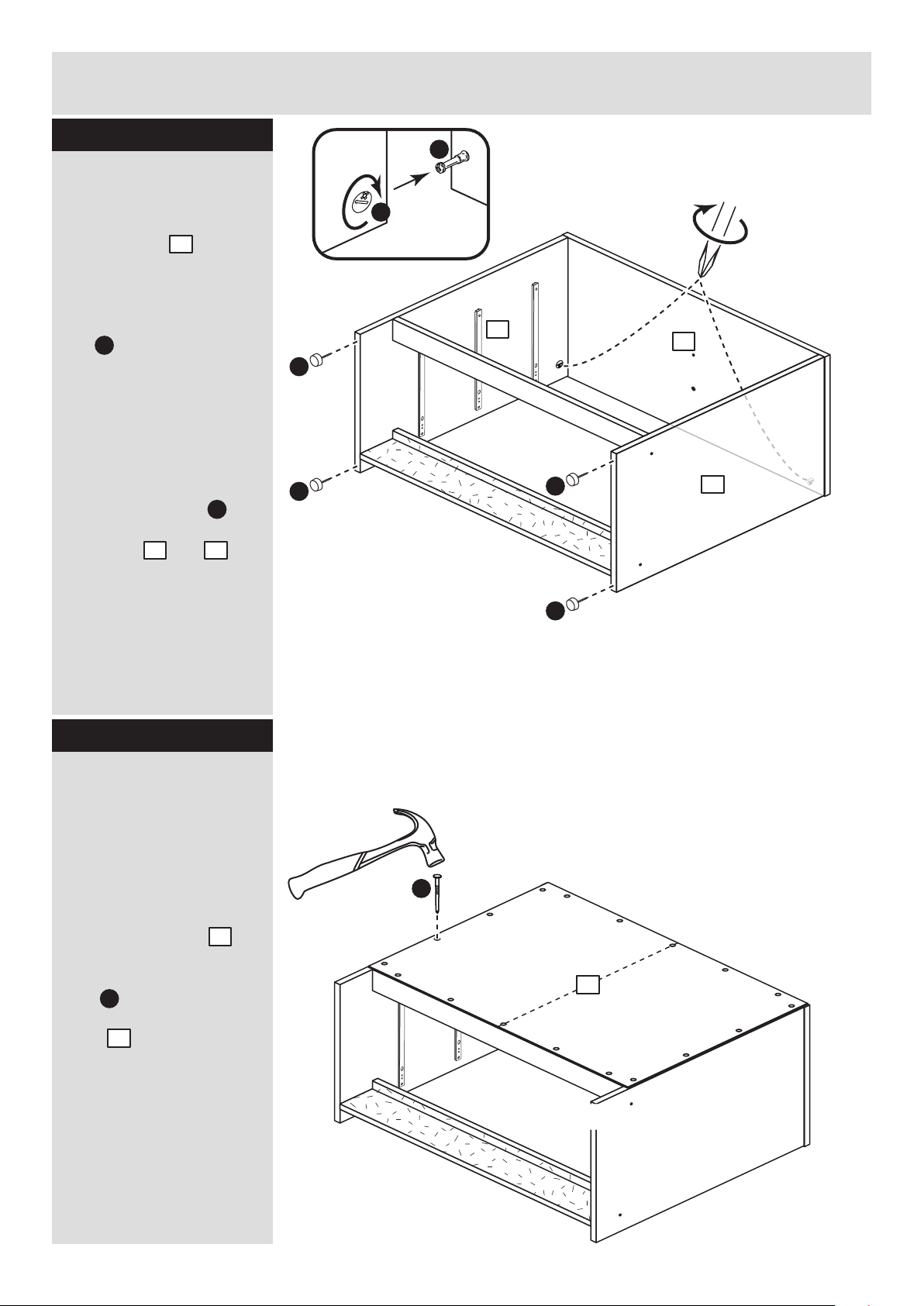
Step 3
F
8
9
Attach the drawer
sides to the drawer
fronts
Push the left drawer sides
. and right drawer sides
. onto the back of the
drawer fronts .
Turn the small locking
nuts on the left
drawer side and right
drawer side .
Note: Turn the locking
nuts clockwise to
secure panels - more
than 1/2 a turn.
8
9
7
F
F
8
9
x 3
x 3
x 3
x 3
B
B
F
F
Note: Due to the manufacturing process, the holes for the
locking nut can be on either surface of the drawer sides.
Note: The locking nuts can be on either surface of the drawer sides.
Make sure that the small groove is on the inside, as shown.
F
F
8
8
9
8
B
B
7
7
Page 6
Assembly Instructions
5
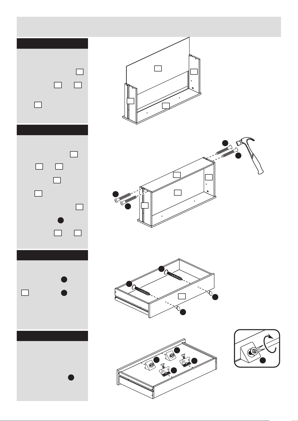
Step 4
7
C
C
x 3
x 3
x 3
x 3
C
C
9
8
11
11
9
8
10
N
H
N
H
7
M
M
M
M
M
Fit the drawer base
Slide the drawer base
down the grooves in the
drawer sides and
and down into the
groove in the drawer
front .
Step 5
Fit the drawer back
Fit the drawer back
between the drawer
sides and .
Make sure that the
drawer base fits into
the groove in the drawer
back .
Hold the drawer back
in position and tap the
knock-in pegs
through the holes in the
drawer sides and .
Step 6
11
8 9
7
10
8 9
11
10
10
C
Attach the handles
Attach 2 handles to
each of the drawer fronts
. using screws .
Note: Do not
overtighten the screw.
N
H
7
8 9
Step 7
Fit the wedgefixes
Turn the drawer
assemblies over and
slide 4 wedgefixes
into the front and back
grooves, as shown, and
tighten up the screws.
M
Page 7
Finished
front edge
Assembly Instructions
6
Step 8
A
Finished
front edge
Finished
front edge
K
I
K
I
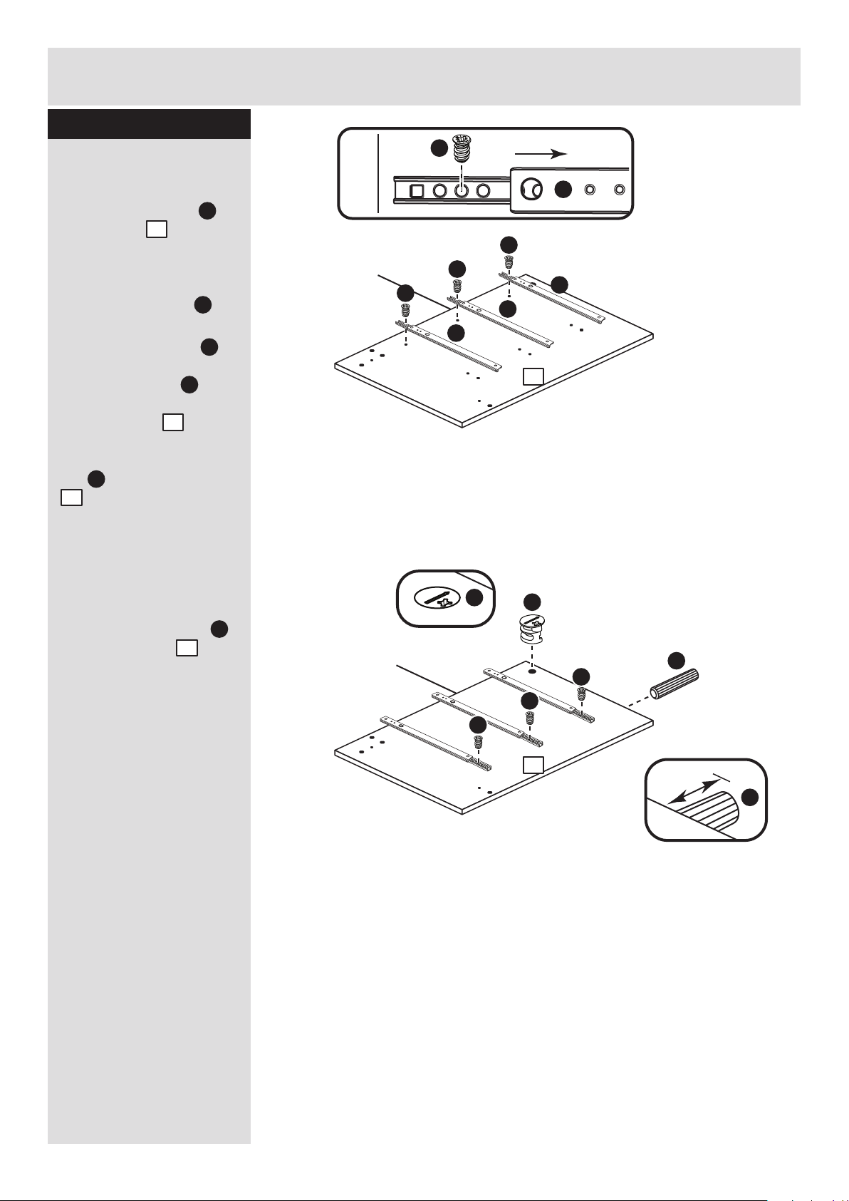
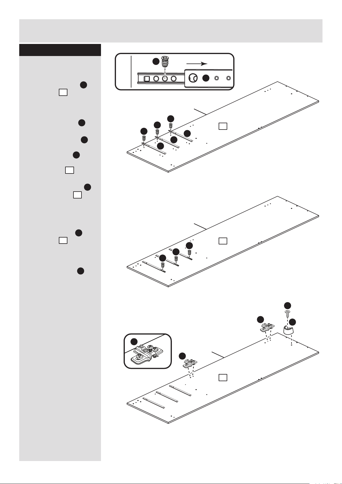
Prepare the left side
a: Place 3 runners on
the left side as
shown. Slide back the
top of runner and use the
2nd hole from the front
to fit the 1st screw .
b: Slide the runner
back the other way and
fit the 2nd screw into
the corresponding hole
in the left side .
Insert a large locking
nut into the left side
. .
Note: The arrow on the
locking nuts must point
towards the hole in the
edge of the panel.
Tap a wooden dowel
into the left side .
Note: Wooden dowels
must not stick out from
the edge by more than
10mm or they may
damage other panels.
1
K
K
1
I
I
K
K
K
E
E
a:
b:
10mm
A
E
1
A
1
1
1
K
I
K
I
Page 8
Assembly Instructions
7
Step 9
A
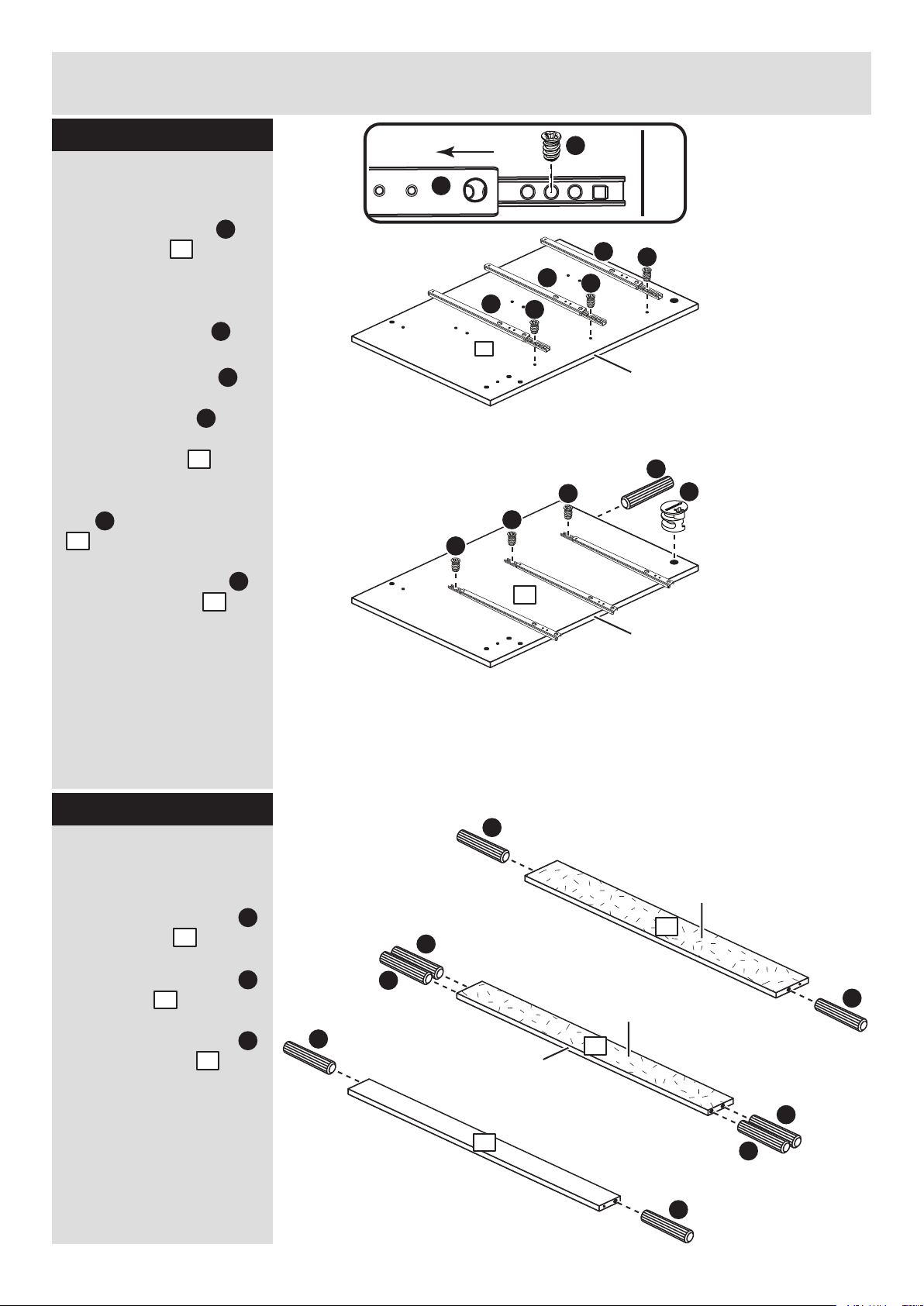
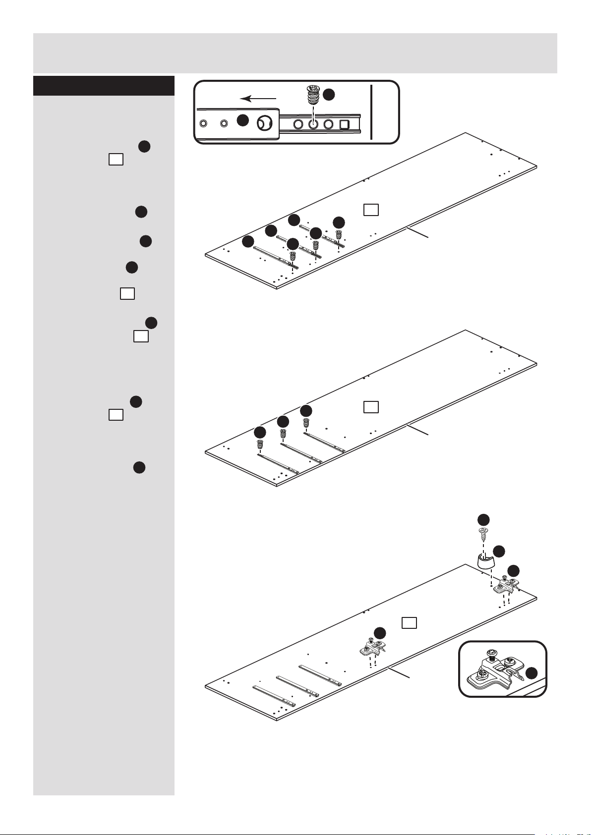
Prepare the right side
a: Place 3 runners on
the right side as
shown. Slide back the
top of runner and use the
2nd hole from the front
to fit the 1st screw .
b: Slide the runner
back the other way and
fit the 2nd screw into
the corresponding hole
in the right side .
Insert a large locking
nut into the right side
. .
Tap a wooden dowel
into the right side .
2
K
K
2
I
I
E
2
A
2
Finished
front edge
K
I
Finished
front edge
Finished
front edge
K
I
K
I
K
I
K
K
K
E
2
2
a:
b:
A
A
A
A
A
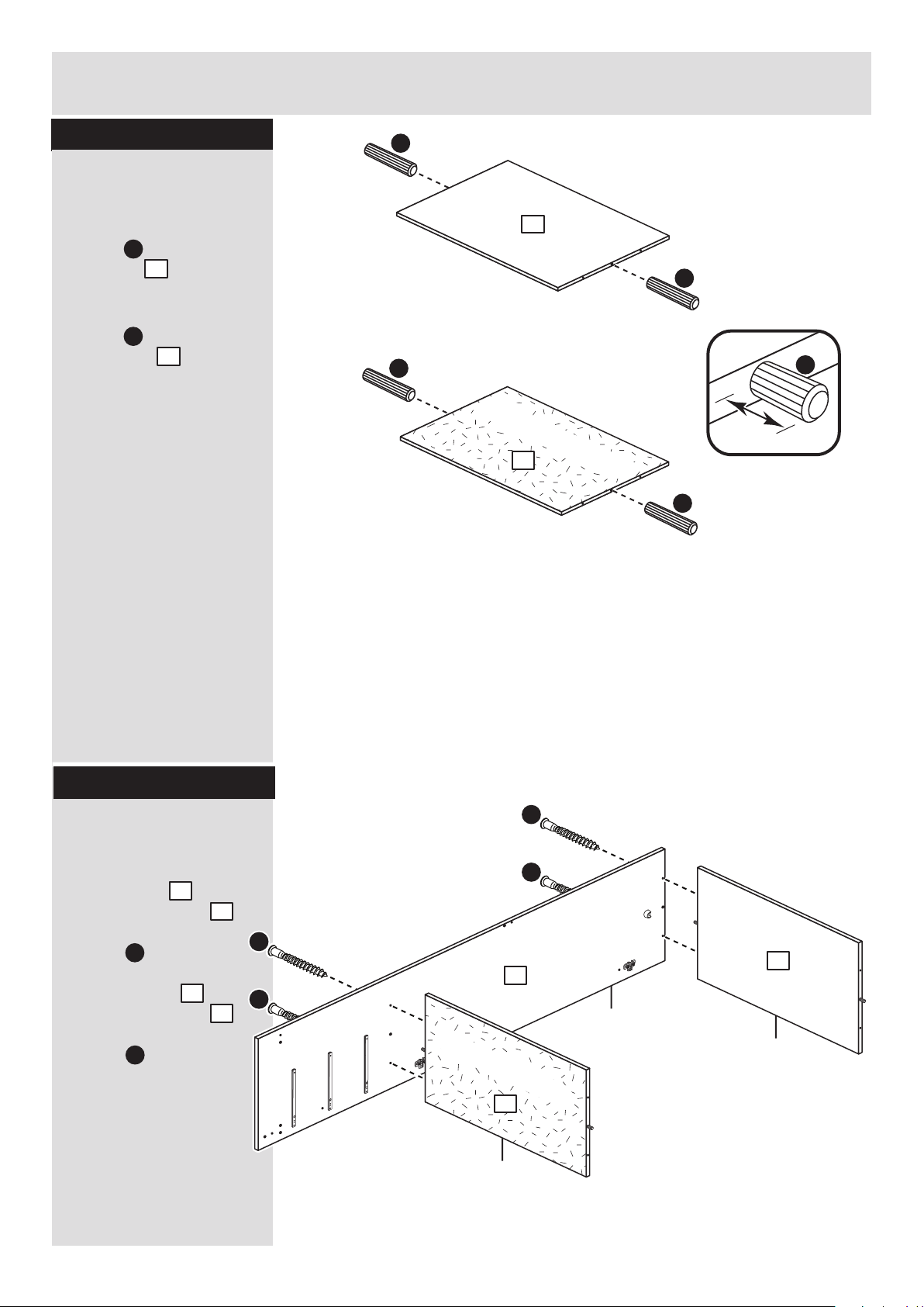
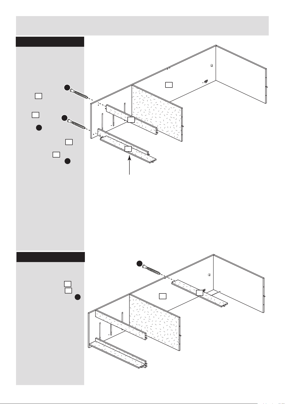
Prepare the plinth, rail
and back rail
Tap 2 wooden dowels
into the plinth .
Tap 4 wooden dowels
into the rail .
Tap 2 wooden dowels
into the back rail .
A
A
Plain chipboard
surface
Plain chipboard
surface
A
The colour of the back
rail may differ from the
main unit colour or may
be plain chipboard.
A
4
A
5
A
6
4
6
5
Finished
front edge
Step 10
Page 9
Finished
front edge
Finished
front edge
Assembly Instructions
8
Step 11
plain chipboard surface
5
G
4
Step 12
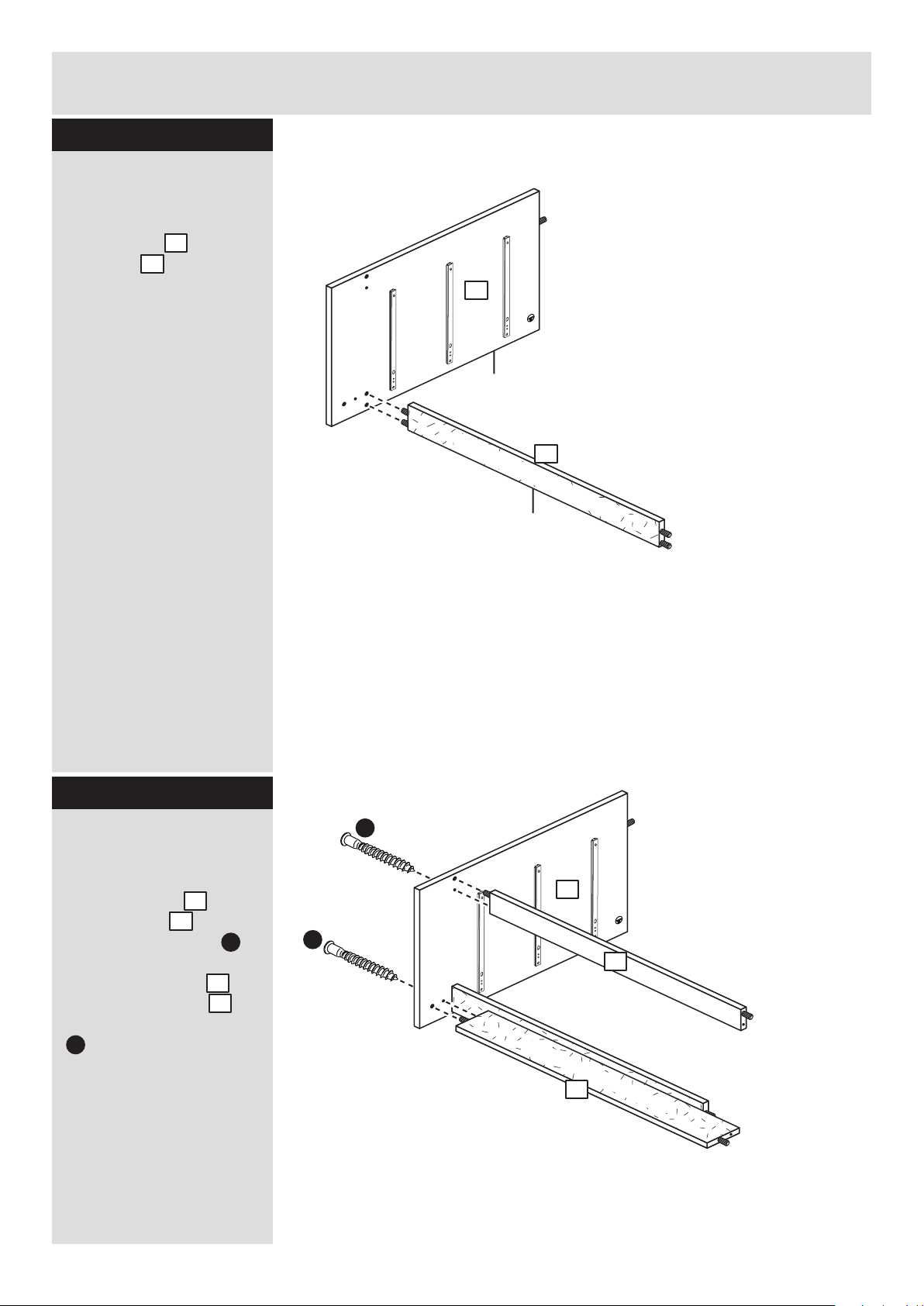
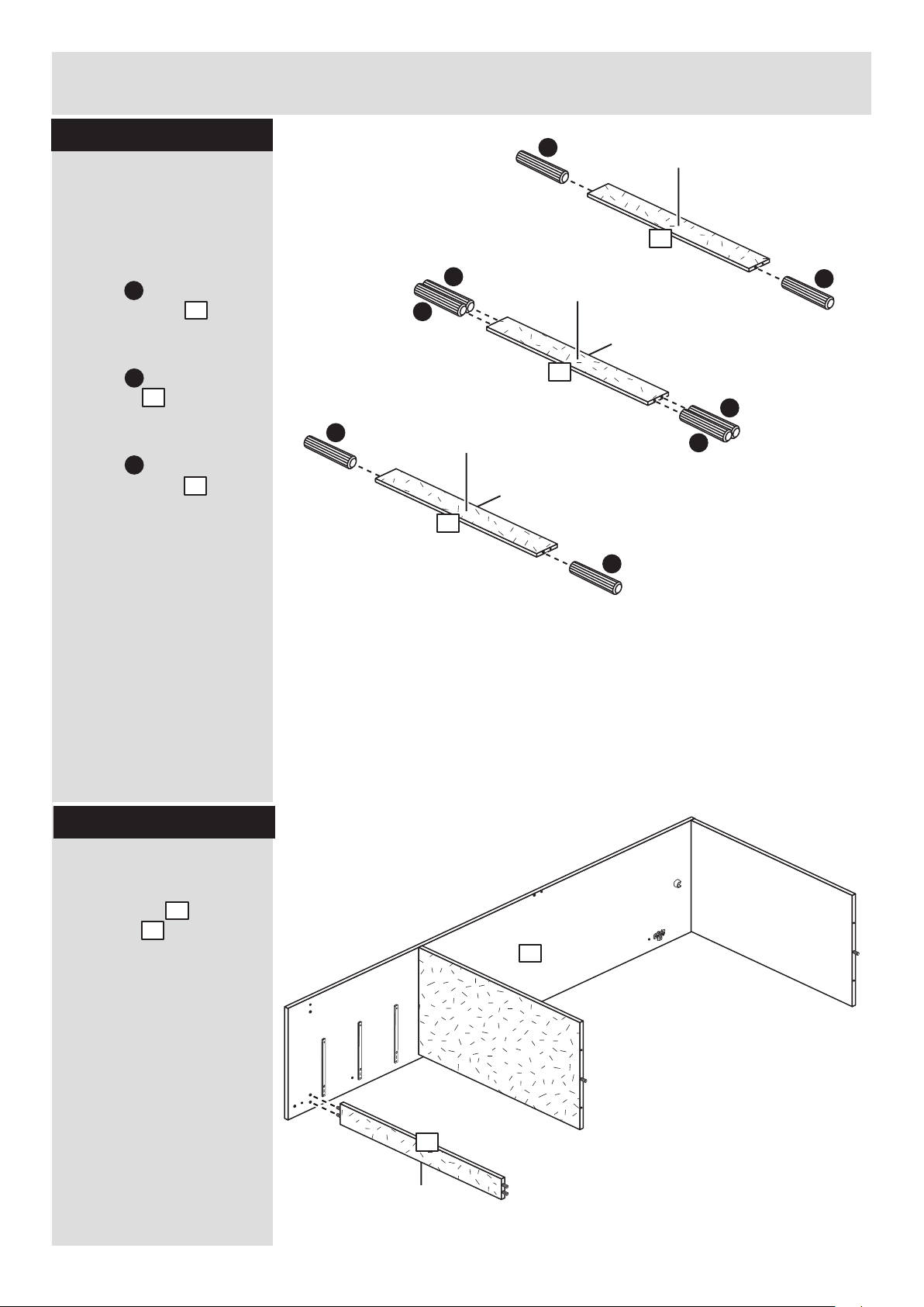
Fit the rail to the right
side
Push the rail onto the
right side .
5
2
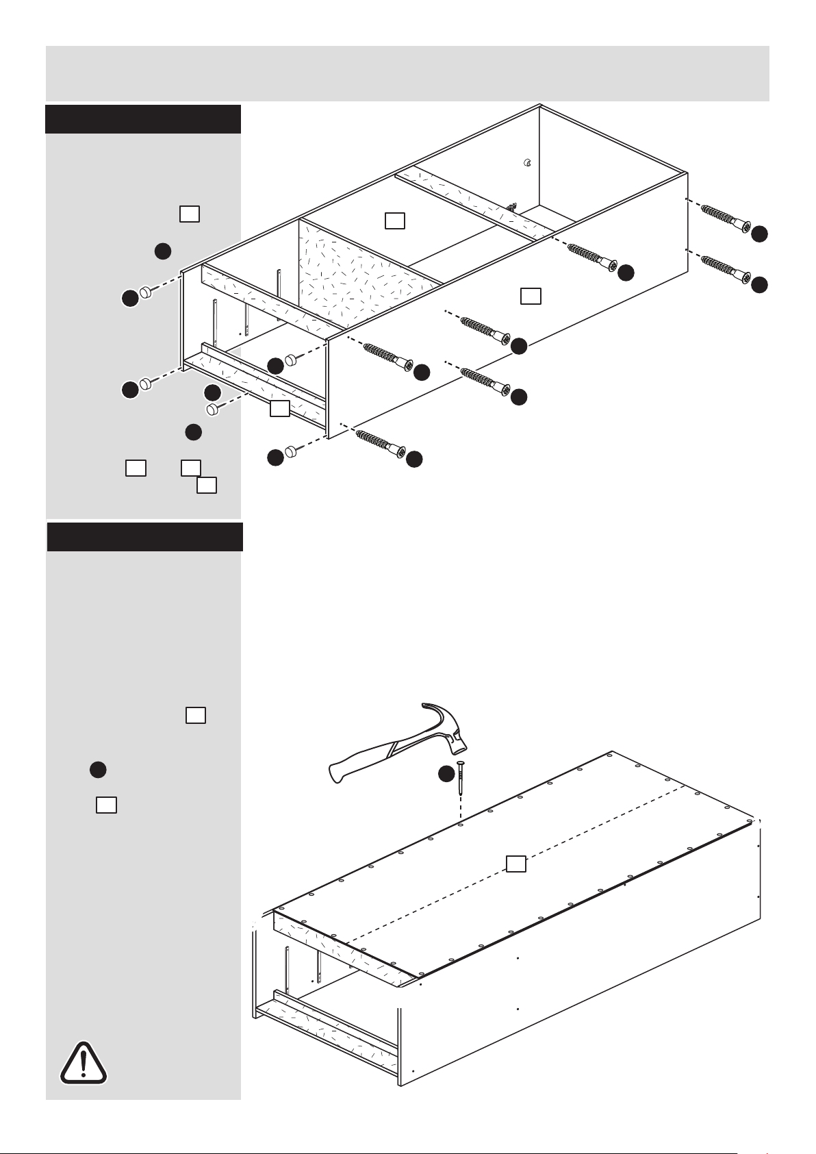
Fit the plinth and back
rail to the right side
Push the plinth onto
the right side and
secure it with screw .
Push the back rail
onto the right side
and secure it with screw
. .
G
4
2
G
6
2
2
G
6
5
2
plain chipboard surface
2
Note: Support the
back rail until the left
side has been fitted
in the next step.
Page 10
Assembly Instructions
9
Step 13
Fit the left side
Push the left side
onto the unit and secure
it with 2 screws .
G
1
Step 14
G
G
1
B
B
Finished
front edge
Prepare the top
Screw 2 metal dowels
into the top .
3
B
3
Page 11
3
Assembly Instructions
10
Step 15
Step 16
Fit the top and the 4
plastic nails
Push the top onto
the side panels.
Use a screwdriver to
tighten the large locking
nut fitted to each
side.
Note: Turn the large
locking nut as far as it
will go - more than 1/2 a
turn.
Tap 2 plastic nails
into the bottom edge of
each side and as
shown.
3
E
E
B
b:
Fit the back
a: Square up the unit by
making sure that
measurement x to x
equals y to y.
b: Place the back
onto the unit.
Nail around the
outside edges of the
back .
Note: Nails should be
spaced about 150mm
apart.
12
D
The measurement from top corner X to bottom corner X must be
equal to the measurement from top corner Y to bottom corner Y
a:
12
D
y
y
x
x
12
L
L
L
L
1 2
L
1
2
Page 12
Assembly Instructions
If you need help or have damaged or missing parts, call the Customer Helpline: 08456 400800
and quote the reference numbers on the component pages.
Argos Ltd, 489-499 Avebury Boulevard, Central Milton Keynes, MK9 2NW
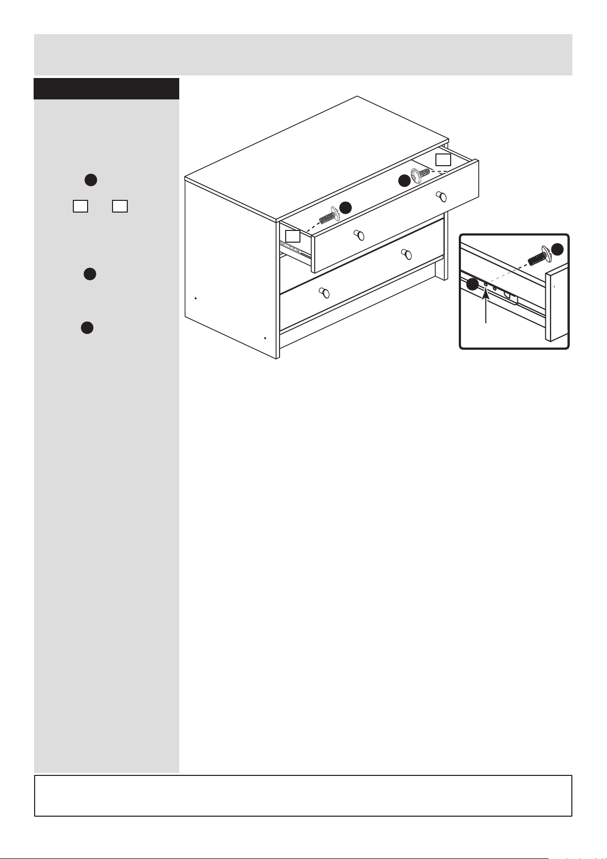
Step 17
ALR3023
Fit the drawers
Starting with the bottom
drawer, slide both the
runners forward and
locate the drawer
sides and
between them, lining up
the holes in the drawer
wrap with the 2nd
'threaded' holes in the
runners .
Working from the inside
of the drawer, insert 2
screws through the
drawer sides and out into
the 2nd threaded hole in
the runner.
Assembly is complete
J
I
I
2nd threaded
hole
I
J
8 9
Note: Do not overtighten the screws.
If they catch on the runner you may
need to loosen them slightly.
J
J
8
9
Page 13
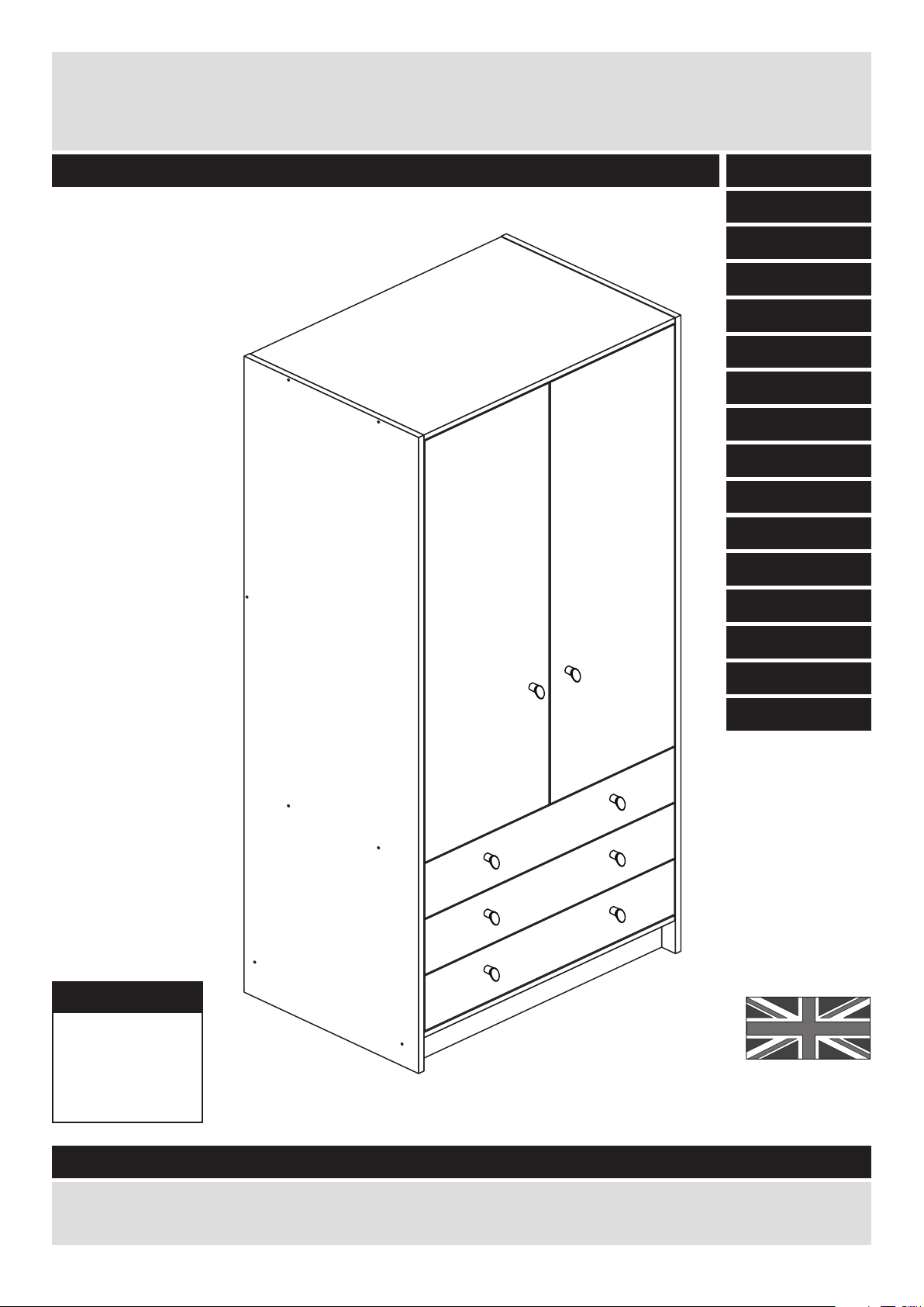
MADE IN
BRITAIN
Dimensions
Width - 74.5cm
Depth - 50cm
Height - 181cm
Malibu - 3 Drawer 2 Door Robe
Assembly Instructions - Please keep for future reference
227/8232
258/7679
If you need help or have damaged or missing parts, call the Customer Helpline: 08456 400800
Issue 8 - 04/09/14
Important - Please read these instructions fully before starting assembly
238/3574
237/1287
258/2904
279/1496
258/8032
279/1960
257/2512
262/6217
255/7788
247/7662
249/6612
278/0830
278/5189
266/7355
Page 14

Safety and Care Advice
Important - Please read these instructions fully before starting assembly
• Warning: This unit weighs
approximately 49.5kgs. Please
lift with care.
• Check you have all the
components and tools listed on
pages 2 and 3.
• Remove all fittings from the
plastic bags and separate them
into their groups.
• Keep children and animals
away from the work area, small
parts could choke if swallowed.
• Parts of the assembly will be
easier with 2 people.
• Make sure you have enough
space to layout the parts before
starting.
• Do not stand or put weight on
the product, this could cause
damage.
• Assemble the item as close to
its final position (in the same
room) as possible.
• Assemble on a soft level
surface to avoid damaging the
unit or your floor (use opened
out unit carton).
• We do not
recommend the
use of power
drill/drivers for
inserting screws,
as this could damage the unit.
Only use hand screwdrivers.
• Safety note: It is
recommended that this unit is
secured to a wall using the
bracket supplied.
• Dispose of all packaging
carefully and responsibly.
1
Care and maintenance
• Only clean using a damp cloth
and mild detergent, do no use
bleach or abrasive cleaners.
• From time to time check that
there are no loose screws on
this unit.
• This product should not be
discarded with household
waste. Take to your local
authority waste disposal centre.
Note: If required the next page
can be cut out and used as
reference throughout the
assembly. Keep this page with
these instructions for future
reference.
Page 15
Components - Panels
Please check you have all the panels listed below
2
1
10
If you have damaged or missing components, call the
Customer Helpline: 08456 400800 quoting the reference
numbers below
2 5
4
3
11
Left Side (D2871A)
(1808 x 496mm)
Base (D2841A)
(716 x 476mm)
Top (D2870A)
(716 x 494mm)
Right Side (D2872A)
(1808 x 496mm)
12
Plinth (D2873A)
(716 x 92mm) x 2
9
6
Back Rail (D2847A)
(716 x 92mm)
Rail (D2874A)
(716 x 92mm)
Drawer Base (T693-367)
(693 x 367mm) x 3
Left Drawer Side (W370-124LH)
(370 x 124mm) x 3
Right Drawer Side (W370-124RH)
(370 x 124mm) x 3
Door (D2857A)
(1198 x 353mm) x 2
Drawer Back (W682-124BCK)
(682 x 124mm) x 3
14
Drawer Front (D2783A)
(710 x 156mm) x 3
Back (X1710-740)
(1710 x 740mm)
7 8
Hanging Rail (FHR704)
(704mm long)
13
15
Page 16
Please check you have all the fittings listed below
3
Components - Fittings
If you have damaged or missing components, call the
Customer Helpline: 08456 400800 quoting the reference
numbers below
Note: The quantities below are the correct amount to complete the assembly. In some cases
more fittings may be supplied than are required.
A
Wooden dowel (F22) x 14
B
Metal dowel (F901) x 6
D F
G
40mm Screw (F910) x 14
J
13mm Screw (F79) x 1
H
25mm Screw (F50) x 8 Handle (F631) x 8
I
L
Nail (F51) x 33
mm 10 20 30 40 50 60 70 80 90 100 110 120 130 140 150 160 170
K
M ON
P Q
Bracket (F327) x 1
Small locking
nut (F3) x 6
Rail holder
(F1014) x 2
E
13mm Screw (F63) x 10
19mm Connecting bolt
(F461) x 2
Hinge plate
(F523) x 4
Hinge (F522) x 4
25mm Connecting sleeve
(F432) x 2
Ruler - Use this ruler to help correctly identify the screws
Tools required
R S
U
Drawer runner (F1004) x 6
Knock-in Peg (F171GY) x 12
C
Plastic Nail (F91) x 5
9mm Screw (F74) x 6
T
9mm Screw (F73) x 12
Wedgefix (F639) 12
Rule
Square
Scissors
Spirit level
Hammer
Bradawl
Electric drill
Step ladder
Cross-head screwdriver
Eye protection (when
using a hammer or drill)
Page 17
Assembly Instructions
4
If you have damaged or missing components, call the
Customer Helpline: 08456 400800 quoting the reference
numbers below
Step 1
x 3
x 3
x 3x 3
B
B
B
E
Step 2
Prepare the 3 drawer
fronts
Screw 2 metal dowels
into each of the drawer
fronts .
Note: Tighten the metal
dowels up fully against
the panels.
B
Prepare the drawer
sides
Insert a small locking
nut into the hole
shown on the left drawer
side and the right
drawer side .
Note: The arrow on the
locking nut must point
towards the hole in the
edge of the panel.
Step 3
E
6
7
Attach the drawer
sides to the drawer
fronts
Push the left drawer sides
. and right drawer sides
. onto the back of the
drawer fronts .
Turn the small locking
nuts on the left
drawer side and right
drawer side .
Note: Turn the locking
nuts clockwise to
secure panels - more
than 1/2 a turn.
6
7
5
E
E
6
E
Note: Due to the manufacturing process, the holes for the
locking nut can be on either surface of the drawer sides.
Note: The locking nuts can be on either surface of the drawer sides.
Make sure that the small groove is on the inside, as shown.
E
E
6
7
5
B
B
5
6
7
7
5
Page 18
Assembly Instructions
5
Step 4
R
R
Fit the drawer base
Slide the drawer base
down the grooves in the
drawer sides and
and down into the
groove in the drawer
front .
Step 5
Fit the drawer back
Fit the drawer back
between the drawer
sides and .
Make sure that the
drawer base fits into
the groove in the drawer
back .
Hold the drawer back
in position and tap the
knock-in pegs
through the holes in the
drawer sides and .
Step 6
9
6 7
5
8
6 7
9
8
8
R
Attach the handles
Attach a handle to
each of the drawer fronts
. using screw .
Note: Do not
overtighten the screw.
I
H
5
x 3
x 3
x 3
R
R
6 7
x 3
Step 7
U
U
Fit the wedgefixes
Turn the drawer
assemblies over and
slide 4 wedgefixes
into the front and back
grooves, as shown, and
tighten up the screws.
U
9
6
7
5
8
6
7
9
H
H
5
I
I
U
U
U
Page 19
Finished
front edge
Assembly Instructions
Step 8
6
T
P
T
P
T
P
Finished
front edge
T
P
a:
Finished
front edge
b:
Finished
front edge
c:
T
T
T
F
K
O
O
O
Prepare the left side
a: Place 3 runners on
the left side as
shown. Slide back the
top of runner and use the
2nd hole from the front
to fit the 1st screw .
b: Slide the runner
back the other way and
fit the 2nd screw into
the corresponding hole
in the left side .
c: Fit 2 hinge plates
onto the left side
making sure that the slot
is facing towards the
finished front edge.
Push a rail holder into
the left side . Make
sure that it is fitted
straight, in line with the
panel edges and then
secure with screw .
1
T
T
1
1
P
P
O
F
K
1
1
1
1
Page 20
Assembly Instructions
Step 9
7
a:
b:
c:
Prepare the right side
a: Place 3 runners on
the right side as
shown. Slide back the
top of runner and use the
2nd hole from the front
to fit the 1st screw .
b: Slide the runner
back the other way and
fit the 2nd screw into
the corresponding hole
in the right side .
c: Fit 2 hinge plates
onto the right side
making sure that the slot
is facing towards the
finished front edge.
Push a rail holder into
the right side . Make
sure that it is fitted
straight, in line with the
panel edges and then
secure with screw .
2
T
T
2
2
P
P
O
F
K
2
Finished
front edge
T
P
T
P
T
P
T
P
T
T
T
O
O
F
K
O
2
2
2
Finished
front edge
Finished
front edge
Finished
front edge
Page 21
Finished
front edge
G
G
G
G
A
A
Assembly Instructions
Step 10
8
Prepare top and base
a: Tap 2 wooden
dowels into the ends
of the top .
b: Tap 2 wooden
dowels into the ends
of the base .
Note: Wooden dowels
must not stick out from
the edge by more than
10mm or they may
damage other panels.
A
A
3
4
a:
b:
Fit the top and base
to the right side
Push the top
onto the right side
and secure with 2
screws .
Push the base
onto the right side
and secure with 2
screws .
3
4
2
2
G
G
Step 11
A
A
4
plain chipboard surface
3
10mm
A
Finished
front edge
Finished
front edge
plain chipboard surface
4
3
2
Page 22
Assembly Instructions
Fit the rail
Push the rail onto the
right side .
Finished
front edge
Finished
front edge
A
A
Assembly Instructions
9
Step 12
Step 13
Prepare the 2 plinths,
the rail and the back
rail
a: Tap 2 wooden
dowels into the ends
of the 2 plinths .
b: Tap 4 wooden
dowels into the ends
of the rail .
c: Tap 2 wooden
dowels into the ends
of the back rail .
A
10
A
12
A
11
11
2
A
A
A
A
A
A
x 2
Plain chipboard
surface
Plain chipboard
surface
Finished
front edge
Plain chipboard
surface
10
12
11
11
2
Page 23
Assembly Instructions
This outer face should
be the same colour as
the main unit panels
10
Step 14
G
Fit the 2 plinths
2 people are needed
here
a: Push the
plinth at the
front of the unit
onto the right
side and
secure with
screw .
b: Push the plinth at
the back of the unit onto
the right side and
secure with screw .
Note: Support the plinth
at the back of the unit
until the left side has
been fitted.
10
2
G
Fit the back rail
Push the back rail
onto the right side
and secure with screw .
Note: Support the back
rail until the left side has
been fitted.
G
12
2
Step 15
G
10
2
G
a:
b:
G
Finished
front edge
10
10
12
2
2
Page 24
Assembly Instructions
11
Step 16
Step 17
Fit the left side and
the 4 plastic nails
Push the left side
onto the unit and secure
with 7 screws .
Tap 2 plastic nails
into the bottom edge of
each end and
and 1 into the plinth
as shown.
G
1
G
G
G
G
G
G
G
Warning: The
robe is heavy.
Lift with care.
The measurement from top corner X to bottom corner X must be
equal to the measurement from top corner Y to bottom corner Y
a:
D
15
yy
yy
x
x
1
C
C
C
C
C
1 2
2
10
10
C
b:
D
Fit the back
a: Square up the unit by
making sure that
measurement x to x
equals y to y.
b: Place the back
onto the unit.
Nail around the
outside edges of the
back .
Note: Nails should be
spaced about 150mm
apart.
Stand the unit up for
the next step.
15
D
15
Page 25
Assembly Instructions
12
Step 18
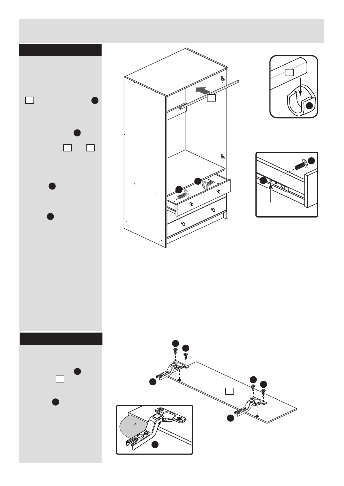
Fit the hanging rails
and drawers
a: Push the hanging rail
. into the rail holders .
b: Starting with the
bottom drawer, slide
both the runners
forward and locate the
drawer sides and
between them, lining up
the holes in the drawer
wrap with the 2nd
'threaded' holes in the
runners .
Working from the inside
of the drawer, insert 2
screws through the
drawer sides and out into
the 2nd threaded hole in
the runner.
Note: Do not overtighten
the screws.
If they catch on the
runner you may need to
loosen them slightly.
13
F
13
F
b:
a:
2nd threaded
hole
P
S
P
6 7
P
S
S
S
13
Step 19
Prepare the 2 doors
Push fit 2 hinges into
each door .
Secure each hinge with
2 screws .
Note: Before securing
with the screws, make
sure that the hinges are
positioned at 90 degrees
with the edge of the
door.
K
Q
14
Q
K
K
90
Q
Q
K
K
14
x 2
Page 26
Assembly Instructions
Small piece of
waste wood
14
Small piece of
waste wood
14
13
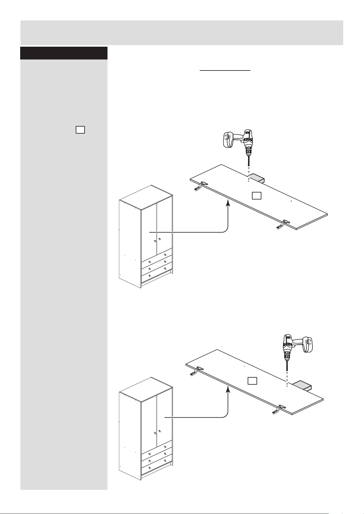
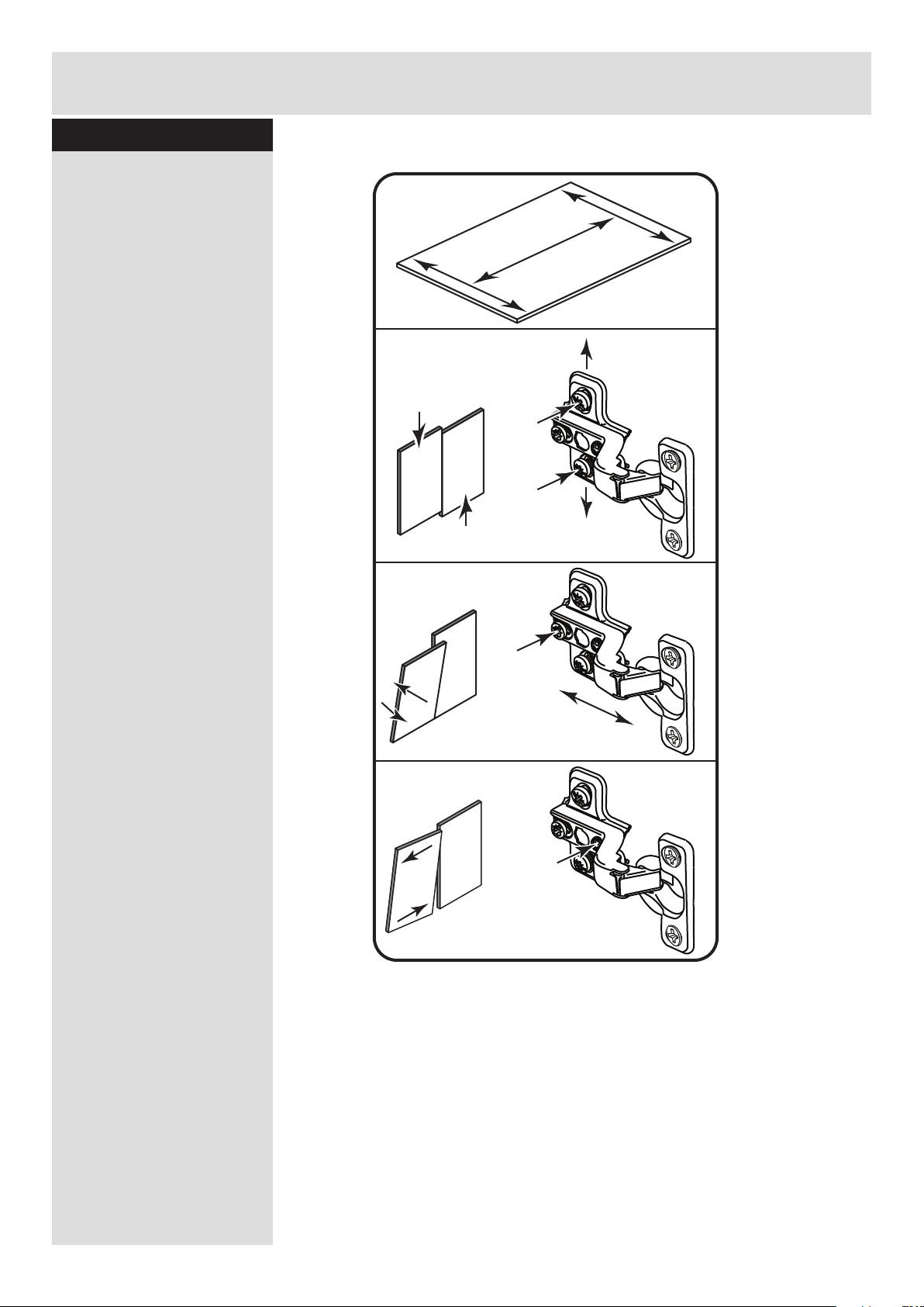
Step 20
Drill a handle hole in
each door
Important: Please follow
these instructions
carefully.
Lay the 2 doors
down onto a smooth
surface.
Check that the hinges
and holes are in the
same place as the
diagrams.
Note: We recommend
the use of a small piece
of waste wood, placed
behind the hole while
drilling, to reduce the
possibility of any
breakout.
Using the pilot hole in
the rear face of the door,
drill through the hole
indicated opposite, using
a 2.5mm diameter drill.
Turn the door over and
open out the 2.5mm hole
that you have just drilled
by drilling back through it
with a 5mm drill.
IMPORTANT
Carefully choose which hole
you need to drill in each door
14
ONLY drill this
hole in 1 door
This will be
the left door
ONLY drill this
hole in 1 door
This will be
the right door
x 1
x 1
Page 27
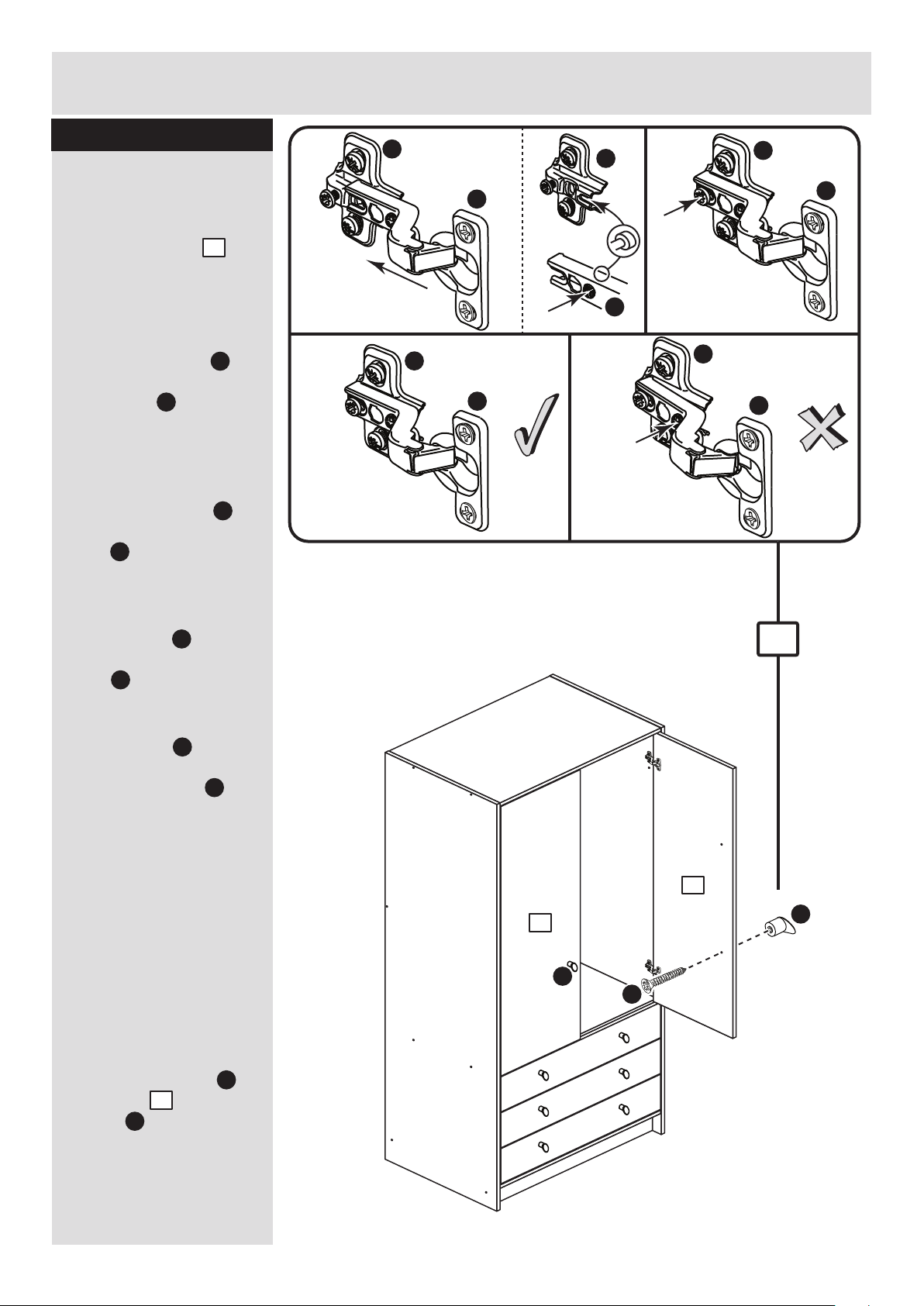
Assembly Instructions
14
Step 21
Fit doors and handles
Note: The easiest way to
attach each door is
to fit the top hinge first,
then align and fit the
other hinges.
a: Push the hinge
onto the front part of the
hinge plate .
The recess at the bottom
of screw B goes into the
slot in the hinge plate.
b: Keep the hinge
FLAT against the hinge
plate as you slide it
across as far as it will go.
Tighten screw A.
c: The hinge must be
flat against the hinge
plate prior to any
adjustment.
d: The hinge must
NOT be AT AN ANGLE
to the hinge plate
when assembled.
This would indicate that
the recess at the bottom
of screw B had not
located in the slot in the
hinge plate and the hinge
would not be secure.
Remove the hinge from
the hinge plate and then
re-assemble being
careful to follow
instructions a-c.
e: Attach a handle to
each door using
screws .
Q
Q
Q
O
O
O
Q
O
I
H
14
14
a: b:
c: d:
O
Q
O
O
B
O
Q
Q
Q
A
Q
O
B
e:
Note: When fitting the doors, make sure
that the handle hole you had to drill is
nearest to the bottom of each door.
I
H
I
14
14
Page 28
Assembly Instructions
15
Step 22
b:
c:
d:
a:
Adjust the doors if
needed
a: Before adjusting the
doors, use a spirit level
to check the base (or
top) of the unit is level,
front-to-back and
side-to-side in the 3
positions shown.
Use suitable packing
pieces (not supplied) to
make the unit level
BEFORE making any
adjustment to the hinges,
as shown.
b: Height adjustment.
Loosen screws A on
hinge plates and move
door up or down as
required.
Retighten screw A.
c: Forward and Back
adjustment.
Loosen screw B on hinge
plate and move door in
or out as required.
Retighten screw B.
d: Sideways
adjustment.
To move door ‘out’
loosen screw C.
To move door ‘in’ tighten
screw C.
A
A
B
C
Page 29
Assembly Instructions
16
Step 23
Joining units together
Fittings have been
supplied so you are able
to join units together.
Make sure that your first
unit is level.
Push the other unit up
against the first unit and
ensure both units are
level.
Check that the ends are
flush and in line, then
clamp them together.
Using a 5mm drill bit,
drill through the 2 holes
(shown circled) in the
side panel into the
adjoining side panel of
the other unit.
Push the connecting
sleeves into the holes
and then screw the
connecting bolts in
from the other side.
5mm
N
M
N
M
N
M
Page 30
Assembly Instructions
If you need help or have damaged or missing parts, call the Customer Helpline: 08456 400800
and quote the reference numbers on the component pages.
Argos Ltd, 489-499 Avebury Boulevard, Central Milton Keynes, MK9 2NW
17
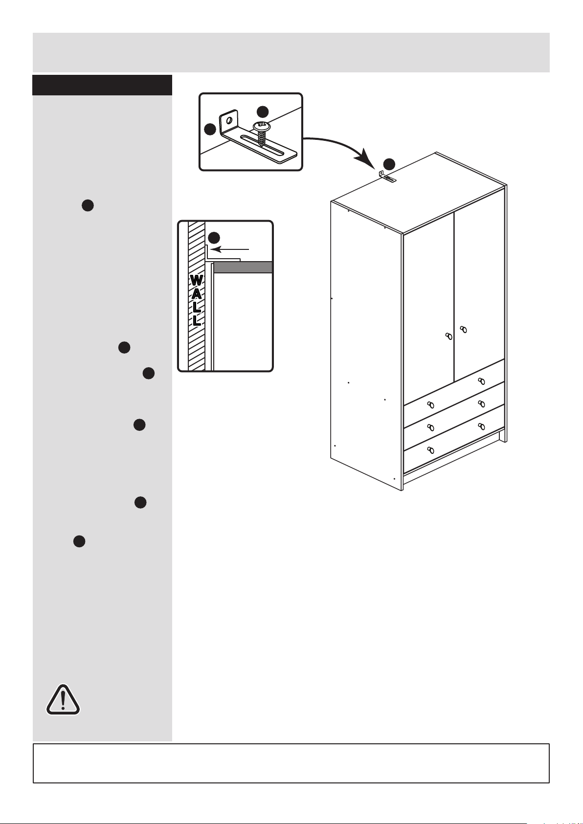
Step 24
Attach bracket to top
To prevent possible
overbalancing, we
recommend that this unit
is secured to a suitable
wall by use of the
bracket fitted to the
top of the unit.
Fixings are not supplied,
as they will need to suit
the wall type and the
length of screw will
depend on the distance
from the back of the unit
to the wall.
Fix the bracket
loosely onto the top of
the unit using screw
and mark the wall for the
wall fixing.
Swivel the bracket
away from the wall and
drill a hole in the wall
using a suitable drill bit
and fit your wall fixing.
Swivel the bracket
back and fix the bracket
to the wall, then tighten
screw .
Note: Take care when
drilling the wall that you
do not drill into any
pipes, wires etc.
If in doubt, consult an
expert.
Assembly is complete
Warning: The
unit is heavy.
Lift with care.
L
L
J
L
L
J
Top of Unit
WALL
WALL
Back of Unit
L
L
J
L
Page 31

Page 32

ALR3033
Page 33

MADE IN
BRITAIN
Dimensions
Width - 74.5cm
Depth - 50cm
Height - 181cm
Malibu - 3 Drawer 2 Door Robe
Assembly Instructions - Please keep for future reference
227/8232
258/7679
If you need help or have damaged or missing parts, call the Customer Helpline: 03456 400800
Issue 9 - 12/01/15
Important - Please read these instructions fully before starting assembly
238/3574
237/1287
258/2904
279/1496
258/8032
279/1960
257/2512
262/6217
255/7788
247/7662
249/6612
278/0830
278/5189
266/7355
Page 34

Safety and Care Advice
Important - Please read these instructions fully before starting assembly
• Warning: This unit weighs
approximately 49.5kgs. Please
lift with care.
• Check you have all the
components and tools listed on
pages 2 and 3.
• Remove all fittings from the
plastic bags and separate them
into their groups.
• Keep children and animals
away from the work area, small
parts could choke if swallowed.
• Parts of the assembly will be
easier with 2 people.
• Make sure you have enough
space to layout the parts before
starting.
• Do not stand or put weight on
the product, this could cause
damage.
• Assemble the item as close to
its final position (in the same
room) as possible.
• Assemble on a soft level
surface to avoid damaging the
unit or your floor (use opened
out unit carton).
• We do not
recommend the
use of power
drill/drivers for
inserting screws,
as this could damage the unit.
Only use hand screwdrivers.
• Safety note: It is
recommended that this unit is
secured to a wall using the
strap supplied.
• Dispose of all packaging
carefully and responsibly.
1
Care and maintenance
• Only clean using a damp cloth
and mild detergent, do no use
bleach or abrasive cleaners.
• From time to time check that
there are no loose screws on
this unit.
• This product should not be
discarded with household
waste. Take to your local
authority waste disposal centre.
Note: If required the next page
can be cut out and used as
reference throughout the
assembly. Keep this page with
these instructions for future
reference.
Page 35

Components - Panels
Please check you have all the panels listed below
2
1
10
If you have damaged or missing components, call the
Customer Helpline: 03456 400800 quoting the reference
numbers below
2 5
4
3
11
Left Side (D2871A)
(1808 x 496mm)
Base (D2841A)
(716 x 476mm)
Top (D2870A)
(716 x 494mm)
Right Side (D2872A)
(1808 x 496mm)
12
Plinth (D2873A)
(716 x 92mm) x 2
9
6
Back Rail (D2847A)
(716 x 92mm)
Rail (D2874A)
(716 x 92mm)
Drawer Base (T693-367)
(693 x 367mm) x 3
Left Drawer Side (W370-124LH)
(370 x 124mm) x 3
Right Drawer Side (W370-124RH)
(370 x 124mm) x 3
Door (D2857A)
(1198 x 353mm) x 2
Drawer Back (W682-124BCK)
(682 x 124mm) x 3
14
Drawer Front (D2783A)
(710 x 156mm) x 3
Back (X1710-740)
(1710 x 740mm)
7 8
Hanging Rail (FHR704)
(704mm long)
13
15
Page 36

Please check you have all the fittings listed below
3
Components - Fittings
If you have damaged or missing components, call the
Customer Helpline: 03456 400800 quoting the reference
numbers below
Note: The quantities below are the correct amount to complete the assembly. In some cases
more fittings may be supplied than are required.
A
Wooden dowel (F22) x 14
B
Metal dowel (F901) x 6
D F
G
40mm Screw (F910) x 14
H
25mm Screw (F50) x 8 Handle (F631) x 8
I
Nail (F51) x 33
mm 10 20 30 40 50 60 70 80 90 100 110 120 130 140 150 160 170
K
M ON
P Q
Small locking
nut (F3) x 6
Rail holder
(F1014) x 2
E
13mm Screw (F63) x 10
19mm Connecting bolt
(F461) x 2
Hinge plate
(F523) x 4
Hinge (F522) x 4
25mm Connecting sleeve
(F432) x 2
Ruler - Use this ruler to help correctly identify the screws
Tools required
R S
J
Drawer runner (F1004) x 6
Knock-in Peg (F171GY) x 12
C
Plastic Nail (F91) x 5
9mm Screw (F74) x 6
L
9mm Screw (F73) x 12
Wedgefix (F639) 12
Rule
Square
Scissors
Spirit level
Hammer
Bradawl
Electric drill
Step ladder
Cross-head screwdriver
Eye protection (when
using a hammer or drill)
T
Strap
Screw Washer x 2
Overbalance protector kit (F269) x 1
Page 37

Assembly Instructions
4
If you have damaged or missing components, call the
Customer Helpline: 08456 400800 quoting the reference
numbers below
Step 1
x 3
x 3
x 3x 3
B
B
B
E
Step 2
Prepare the 3 drawer
fronts
Screw 2 metal dowels
into each of the drawer
fronts .
Note: Tighten the metal
dowels up fully against
the panels.
B
Prepare the drawer
sides
Insert a small locking
nut into the hole
shown on the left drawer
side and the right
drawer side .
Note: The arrow on the
locking nut must point
towards the hole in the
edge of the panel.
Step 3
E
6
7
Attach the drawer
sides to the drawer
fronts
Push the left drawer sides
. and right drawer sides
. onto the back of the
drawer fronts .
Turn the small locking
nuts on the left
drawer side and right
drawer side .
Note: Turn the locking
nuts clockwise to
secure panels - more
than 1/2 a turn.
6
7
5
E
E
6
E
Note: Due to the manufacturing process, the holes for the
locking nut can be on either surface of the drawer sides.
Note: The locking nuts can be on either surface of the drawer sides.
Make sure that the small groove is on the inside, as shown.
E
E
6
7
5
B
B
5
6
7
7
5
Page 38

Assembly Instructions
5
Step 4
R
R
Fit the drawer base
Slide the drawer base
down the grooves in the
drawer sides and
and down into the
groove in the drawer
front .
Step 5
Fit the drawer back
Fit the drawer back
between the drawer
sides and .
Make sure that the
drawer base fits into
the groove in the drawer
back .
Hold the drawer back
in position and tap the
knock-in pegs
through the holes in the
drawer sides and .
Step 6
9
6 7
5
8
6 7
9
8
8
R
Attach the handles
Attach a handle to
each of the drawer fronts
. using screw .
Note: Do not
overtighten the screw.
I
H
5
x 3
x 3
x 3
R
R
6 7
x 3
Step 7
J
J
Fit the wedgefixes
Turn the drawer
assemblies over and
slide 4 wedgefixes
into the front and back
grooves, as shown, and
tighten up the screws.
J
9
6
7
5
8
6
7
9
H
H
5
I
I
J
J
J
Page 39

Finished
front edge
Assembly Instructions
Step 8
6
L
P
L
P
L
P
Finished
front edge
L
P
a:
Finished
front edge
b:
Finished
front edge
c:
L
L
L
F
K
O
O
O
Prepare the left side
a: Place 3 runners on
the left side as
shown. Slide back the
top of runner and use the
2nd hole from the front
to fit the 1st screw .
b: Slide the runner
back the other way and
fit the 2nd screw into
the corresponding hole
in the left side .
c: Fit 2 hinge plates
onto the left side
making sure that the slot
is facing towards the
finished front edge.
Push a rail holder into
the left side . Make
sure that it is fitted
straight, in line with the
panel edges and then
secure with screw .
1
L
L
1
1
P
P
O
F
K
1
1
1
1
Page 40

Assembly Instructions
Step 9
7
a:
b:
c:
Prepare the right side
a: Place 3 runners on
the right side as
shown. Slide back the
top of runner and use the
2nd hole from the front
to fit the 1st screw .
b: Slide the runner
back the other way and
fit the 2nd screw into
the corresponding hole
in the right side .
c: Fit 2 hinge plates
onto the right side
making sure that the slot
is facing towards the
finished front edge.
Push a rail holder into
the right side . Make
sure that it is fitted
straight, in line with the
panel edges and then
secure with screw .
2
L
L
2
2
P
P
O
F
K
2
Finished
front edge
L
P
L
P
L
P
L
P
L
L
L
O
O
F
K
O
2
2
2
Finished
front edge
Finished
front edge
Finished
front edge
Page 41

Finished
front edge
G
G
G
G
A
A
Assembly Instructions
Step 10
8
Prepare top and base
a: Tap 2 wooden
dowels into the ends
of the top .
b: Tap 2 wooden
dowels into the ends
of the base .
Note: Wooden dowels
must not stick out from
the edge by more than
10mm or they may
damage other panels.
A
A
3
4
a:
b:
Fit the top and base
to the right side
Push the top
onto the right side
and secure with 2
screws .
Push the base
onto the right side
and secure with 2
screws .
3
4
2
2
G
G
Step 11
A
A
4
plain chipboard surface
3
10mm
A
Finished
front edge
Finished
front edge
plain chipboard surface
4
3
2
Page 42

Assembly Instructions
Fit the rail
Push the rail onto the
right side .
Finished
front edge
Finished
front edge
A
A
Assembly Instructions
9
Step 12
Step 13
Prepare the 2 plinths,
the rail and the back
rail
a: Tap 2 wooden
dowels into the ends
of the 2 plinths .
b: Tap 4 wooden
dowels into the ends
of the rail .
c: Tap 2 wooden
dowels into the ends
of the back rail .
A
10
A
12
A
11
11
2
A
A
A
A
A
A
x 2
Plain chipboard
surface
Plain chipboard
surface
Finished
front edge
Plain chipboard
surface
10
12
11
11
2
Page 43

Assembly Instructions
This outer face should
be the same colour as
the main unit panels
10
Step 14
G
Fit the 2 plinths
2 people are needed
here
a: Push the
plinth at the
front of the unit
onto the right
side and
secure with
screw .
b: Push the plinth at
the back of the unit onto
the right side and
secure with screw .
Note: Support the plinth
at the back of the unit
until the left side has
been fitted.
10
2
G
Fit the back rail
Push the back rail
onto the right side
and secure with screw .
Note: Support the back
rail until the left side has
been fitted.
G
12
2
Step 15
G
10
2
G
a:
b:
G
Finished
front edge
10
10
12
2
2
Page 44

Assembly Instructions
11
Step 16
Step 17
Fit the left side and
the 4 plastic nails
Push the left side
onto the unit and secure
with 7 screws .
Tap 2 plastic nails
into the bottom edge of
each end and
and 1 into the plinth
as shown.
G
1
G
G
G
G
G
G
G
Warning: The
robe is heavy.
Lift with care.
The measurement from top corner X to bottom corner X must be
equal to the measurement from top corner Y to bottom corner Y
a:
D
15
yy
yy
x
x
1
C
C
C
C
C
1 2
2
10
10
C
b:
D
Fit the back
a: Square up the unit by
making sure that
measurement x to x
equals y to y.
b: Place the back
onto the unit.
Nail around the
outside edges of the
back .
Note: Nails should be
spaced about 150mm
apart.
Stand the unit up for
the next step.
15
D
15
Page 45

Assembly Instructions
12
Step 18
Fit the hanging rails
and drawers
a: Push the hanging rail
. into the rail holders .
b: Starting with the
bottom drawer, slide
both the runners
forward and locate the
drawer sides and
between them, lining up
the holes in the drawer
wrap with the 2nd
'threaded' holes in the
runners .
Working from the inside
of the drawer, insert 2
screws through the
drawer sides and out into
the 2nd threaded hole in
the runner.
Note: Do not overtighten
the screws.
If they catch on the
runner you may need to
loosen them slightly.
13
F
13
F
b:
a:
2nd threaded
hole
P
S
P
6 7
P
S
S
S
13
Step 19
Prepare the 2 doors
Push fit 2 hinges into
each door .
Secure each hinge with
2 screws .
Note: Before securing
with the screws, make
sure that the hinges are
positioned at 90 degrees
with the edge of the
door.
K
Q
14
Q
K
K
90
Q
Q
K
K
14
x 2
Page 46

Assembly Instructions
Small piece of
waste wood
14
Small piece of
waste wood
14
13
Step 20
Drill a handle hole in
each door
Important: Please follow
these instructions
carefully.
Lay the 2 doors
down onto a smooth
surface.
Check that the hinges
and holes are in the
same place as the
diagrams.
Note: We recommend
the use of a small piece
of waste wood, placed
behind the hole while
drilling, to reduce the
possibility of any
breakout.
Using the pilot hole in
the rear face of the door,
drill through the hole
indicated opposite, using
a 2.5mm diameter drill.
Turn the door over and
open out the 2.5mm hole
that you have just drilled
by drilling back through it
with a 5mm drill.
IMPORTANT
Carefully choose which hole
you need to drill in each door
14
ONLY drill this
hole in 1 door
This will be
the left door
ONLY drill this
hole in 1 door
This will be
the right door
x 1
x 1
Page 47

Assembly Instructions
14
Step 21
Fit doors and handles
Note: The easiest way to
attach each door is
to fit the top hinge first,
then align and fit the
other hinges.
a: Push the hinge
onto the front part of the
hinge plate .
The recess at the bottom
of screw B goes into the
slot in the hinge plate.
b: Keep the hinge
FLAT against the hinge
plate as you slide it
across as far as it will go.
Tighten screw A.
c: The hinge must be
flat against the hinge
plate prior to any
adjustment.
d: The hinge must
NOT be AT AN ANGLE
to the hinge plate
when assembled.
This would indicate that
the recess at the bottom
of screw B had not
located in the slot in the
hinge plate and the hinge
would not be secure.
Remove the hinge from
the hinge plate and then
re-assemble being
careful to follow
instructions a-c.
e: Attach a handle to
each door using
screws .
Q
Q
Q
O
O
O
Q
O
I
H
14
14
a: b:
c: d:
O
Q
O
O
B
O
Q
Q
Q
A
Q
O
B
e:
Note: When fitting the doors, make sure
that the handle hole you had to drill is
nearest to the bottom of each door.
I
H
I
14
14
Page 48

Assembly Instructions
15
Step 22
b:
c:
d:
a:
Adjust the doors if
needed
a: Before adjusting the
doors, use a spirit level
to check the base (or
top) of the unit is level,
front-to-back and
side-to-side in the 3
positions shown.
Use suitable packing
pieces (not supplied) to
make the unit level
BEFORE making any
adjustment to the hinges,
as shown.
b: Height adjustment.
Loosen screws A on
hinge plates and move
door up or down as
required.
Retighten screw A.
c: Forward and Back
adjustment.
Loosen screw B on hinge
plate and move door in
or out as required.
Retighten screw B.
d: Sideways
adjustment.
To move door ‘out’
loosen screw C.
To move door ‘in’ tighten
screw C.
A
A
B
C
Page 49

Assembly Instructions
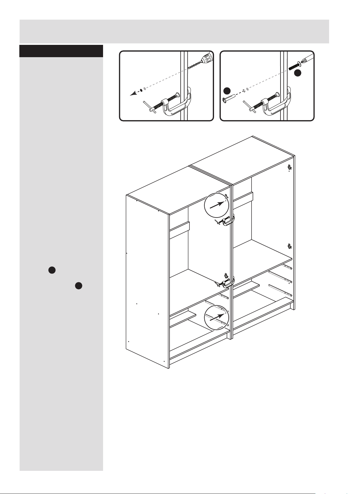
16
Step 23
Joining units together
Fittings have been
supplied so you are able
to join units together.
Make sure that your first
unit is level.
Push the other unit up
against the first unit and
ensure both units are
level.
Check that the ends are
flush and in line, then
clamp them together.
Using a 5mm drill bit,
drill through the 2 holes
(shown circled) in the
side panel into the
adjoining side panel of
the other unit.
Push the connecting
sleeves into the holes
and then screw the
connecting bolts in
from the other side.
5mm
N
M
N
M
N
M
Page 50

Assembly Instructions
If you need help or have damaged or missing parts, call the Customer Helpline: 03456 400800
and quote the reference numbers on the component pages.
Argos Ltd, 489-499 Avebury Boulevard, Central Milton Keynes, MK9 2NW
17
Step 24
L
Fit the overbalance
protector kit
To prevent possible
overbalancing we
recommend that this unit
is secured to a suitable
wall by fitting of the
overbalance protector kit
. to the unit, or an
alternative fixing method
of your choice.
Wall fixings are not
supplied as they will
need to suit the wall
type.
Note: Take care when
drilling the wall that you
do not drill into any
pipes, wires etc.
If in doubt, consult an
expert.
Assembly is complete
WARNING.
This unit is heavy.
Lift and handle with care.
T
T
WALL
Wall fixing
(not supplied)
Screw
(not supplied)
Washer
Strap
T
Strap
Washer
Screw
TOP OF UNIT
T
Page 51

Page 52

ALR3033
Page 53

MADE IN
BRITAIN
Dimensions
Width - 74.5cm
Depth - 50cm
Height - 181cm
Malibu - 3 Drawer 2 Door Robe
Assembly Instructions - Please keep for future reference
227/8232
258/7679
If you need help or have damaged or missing parts, call the Customer Helpline: 03456 400800
Issue 10 - 22/04/15
Important - Please read these instructions fully before starting assembly
238/3574
237/1287
258/2904
279/1496
258/8032
279/1960
257/2512
262/6217
255/7788
247/7662
249/6612
278/0830
278/5189
266/7355
Page 54

Safety and Care Advice
Important - Please read these instructions fully before starting assembly
• Warning: This unit weighs
approximately 49.5kgs. Please
lift with care.
• Check you have all the
components and tools listed on
pages 2 and 3.
• Remove all fittings from the
plastic bags and separate them
into their groups.
• Keep children and animals
away from the work area, small
parts could choke if swallowed.
• Parts of the assembly will be
easier with 2 people.
• Make sure you have enough
space to layout the parts before
starting.
• Do not stand or put weight on
the product, this could cause
damage.
• Assemble the item as close to
its final position (in the same
room) as possible.
• Assemble on a soft level
surface to avoid damaging the
unit or your floor (use opened
out unit carton).
• We do not
recommend the
use of power
drill/drivers for
inserting screws,
as this could damage the unit.
Only use hand screwdrivers.
• Safety note: It is
recommended that this unit is
secured to a wall using the
strap supplied.
• Dispose of all packaging
carefully and responsibly.
1
Care and maintenance
• Only clean using a damp cloth
and mild detergent, do no use
bleach or abrasive cleaners.
• From time to time check that
there are no loose screws on
this unit.
• This product should not be
discarded with household
waste. Take to your local
authority waste disposal centre.
Note: If required the next page
can be cut out and used as
reference throughout the
assembly. Keep this page with
these instructions for future
reference.
Page 55

Components - Panels
Please check you have all the panels listed below
2
1
10
If you have damaged or missing components, call the
Customer Helpline: 03456 400800 quoting the reference
numbers below
2 5
4
3
11
Left Side (D2871A)
(1808 x 496mm)
Base (D2841A)
(716 x 476mm)
Top (D2870A)
(716 x 494mm)
Right Side (D2872A)
(1808 x 496mm)
12
Plinth (D2873A)
(716 x 92mm) x 2
9
6
Back Rail (D2847A)
(716 x 92mm)
Rail (D2874A)
(716 x 92mm)
Drawer Base (T693-367)
(693 x 367mm) x 3
Left Drawer Side (W370-124LH)
(370 x 124mm) x 3
Right Drawer Side (W370-124RH)
(370 x 124mm) x 3
Door (D2857A)
(1198 x 353mm) x 2
Drawer Back (W682-124BCK)
(682 x 124mm) x 3
14
Drawer Front (D2783A)
(710 x 156mm) x 3
Back (X1710-740)
(1710 x 740mm)
7 8
Hanging Rail (FHR704)
(704mm long)
13
15
Page 56

Please check you have all the fittings listed below
3
Components - Fittings
If you have damaged or missing components, call the
Customer Helpline: 03456 400800 quoting the reference
numbers below
Note: The quantities below are the correct amount to complete the assembly. In some cases
more fittings may be supplied than are required.
A
Wooden dowel (F22) x 14
B
Metal dowel (F901) x 6
D F
G
40mm Screw (F910) x 14
H
25mm Screw (F50) x 8 Handle (F631) x 8
I
Nail (F51) x 33
mm 10 20 30 40 50 60 70 80 90 100 110 120 130 140 150 160 170
K
M ON
P Q
Small locking
nut (F3) x 6
Rail holder
(F1014) x 2
E
13mm Screw (F63) x 10
Hinge plate
(F523) x 4
Hinge (F522) x 4
Ruler - Use this ruler to help correctly identify the screws
Tools required
R
J
Drawer runner (F1004) x 6
Knock-in Peg (F171GY) x 12
C
Plastic Nail (F91) x 5
9mm Screw (F74) x 6
L
9mm Screw (F73) x 12
Wedgefix (F639) 12
Rule
Square
Scissors
Spirit level
Hammer
Bradawl
Electric drill
Step ladder
Cross-head screwdriver
Eye protection (when
using a hammer or drill)
Strap Screw Washer x 2
Overbalance protector kit (F269) x 1
Page 57

Assembly Instructions
4
If you have damaged or missing components, call the
Customer Helpline: 08456 400800 quoting the reference
numbers below
Step 1
x 3
x 3
x 3x 3
B
B
B
E
Step 2
Prepare the 3 drawer
fronts
Screw 2 metal dowels
into each of the drawer
fronts .
Note: Tighten the metal
dowels up fully against
the panels.
B
Prepare the drawer
sides
Insert a small locking
nut into the hole
shown on the left drawer
side and the right
drawer side .
Note: The arrow on the
locking nut must point
towards the hole in the
edge of the panel.
Step 3
E
6
7
Attach the drawer
sides to the drawer
fronts
Push the left drawer sides
. and right drawer sides
. onto the back of the
drawer fronts .
Turn the small locking
nuts on the left
drawer side and right
drawer side .
Note: Turn the locking
nuts clockwise to
secure panels - more
than 1/2 a turn.
6
7
5
E
E
6
E
Note: Due to the manufacturing process, the holes for the
locking nut can be on either surface of the drawer sides.
Note: The locking nuts can be on either surface of the drawer sides.
Make sure that the small groove is on the inside, as shown.
E
E
6
7
5
B
B
5
6
7
7
5
Page 58

Assembly Instructions
5
Step 4
N
N
Fit the drawer base
Slide the drawer base
down the grooves in the
drawer sides and
and down into the
groove in the drawer
front .
Step 5
Fit the drawer back
Fit the drawer back
between the drawer
sides and .
Make sure that the
drawer base fits into
the groove in the drawer
back .
Hold the drawer back
in position and tap the
knock-in pegs
through the holes in the
drawer sides and .
Step 6
9
6 7
5
8
6 7
9
8
8
N
Attach the handles
Attach a handle to
each of the drawer fronts
. using screw .
Note: Do not
overtighten the screw.
I
H
5
x 3
x 3
x 3
N
N
6 7
x 3
Step 7
J
J
Fit the wedgefixes
Turn the drawer
assemblies over and
slide 4 wedgefixes
into the front and back
grooves, as shown, and
tighten up the screws.
J
9
6
7
5
8
6
7
9
H
H
5
I
I
J
J
J
Page 59

Finished
front edge
Assembly Instructions
Step 8
6
L
P
L
P
L
P
Finished
front edge
L
P
a:
Finished
front edge
b:
Finished
front edge
c:
L
L
L
F
K
O
O
O
Prepare the left side
a: Place 3 runners on
the left side as
shown. Slide back the
top of runner and use the
2nd hole from the front
to fit the 1st screw .
b: Slide the runner
back the other way and
fit the 2nd screw into
the corresponding hole
in the left side .
c: Fit 2 hinge plates
onto the left side
making sure that the slot
is facing towards the
finished front edge.
Push a rail holder into
the left side . Make
sure that it is fitted
straight, in line with the
panel edges and then
secure with screw .
1
L
L
1
1
P
P
O
F
K
1
1
1
1
Page 60

Assembly Instructions
Step 9
7
a:
b:
c:
Prepare the right side
a: Place 3 runners on
the right side as
shown. Slide back the
top of runner and use the
2nd hole from the front
to fit the 1st screw .
b: Slide the runner
back the other way and
fit the 2nd screw into
the corresponding hole
in the right side .
c: Fit 2 hinge plates
onto the right side
making sure that the slot
is facing towards the
finished front edge.
Push a rail holder into
the right side . Make
sure that it is fitted
straight, in line with the
panel edges and then
secure with screw .
2
L
L
2
2
P
P
O
F
K
2
Finished
front edge
L
P
L
P
L
P
L
P
L
L
L
O
O
F
K
O
2
2
2
Finished
front edge
Finished
front edge
Finished
front edge
Page 61

Finished
front edge
G
G
G
G
A
A
Assembly Instructions
Step 10
8
Prepare top and base
a: Tap 2 wooden
dowels into the ends
of the top .
b: Tap 2 wooden
dowels into the ends
of the base .
Note: Wooden dowels
must not stick out from
the edge by more than
10mm or they may
damage other panels.
A
A
3
4
a:
b:
Fit the top and base
to the right side
Push the top
onto the right side
and secure with 2
screws .
Push the base
onto the right side
and secure with 2
screws .
3
4
2
2
G
G
Step 11
A
A
4
plain chipboard surface
3
10mm
A
Finished
front edge
Finished
front edge
plain chipboard surface
4
3
2
Page 62

Assembly Instructions
Fit the rail
Push the rail onto the
right side .
Finished
front edge
Finished
front edge
A
A
Assembly Instructions
9
Step 12
Step 13
Prepare the 2 plinths,
the rail and the back
rail
a: Tap 2 wooden
dowels into the ends
of the 2 plinths .
b: Tap 4 wooden
dowels into the ends
of the rail .
c: Tap 2 wooden
dowels into the ends
of the back rail .
A
10
A
12
A
11
11
2
A
A
A
A
A
A
x 2
Plain chipboard
surface
Plain chipboard
surface
Finished
front edge
Plain chipboard
surface
10
12
11
11
2
Page 63

Assembly Instructions
This outer face should
be the same colour as
the main unit panels
10
Step 14
G
Fit the 2 plinths
2 people are needed
here
a: Push the
plinth at the
front of the unit
onto the right
side and
secure with
screw .
b: Push the plinth at
the back of the unit onto
the right side and
secure with screw .
Note: Support the plinth
at the back of the unit
until the left side has
been fitted.
10
2
G
Fit the back rail
Push the back rail
onto the right side
and secure with screw .
Note: Support the back
rail until the left side has
been fitted.
G
12
2
Step 15
G
10
2
G
a:
b:
G
Finished
front edge
10
10
12
2
2
Page 64

Assembly Instructions
11
Step 16
Step 17
Fit the left side and
the 4 plastic nails
Push the left side
onto the unit and secure
with 7 screws .
Tap 2 plastic nails
into the bottom edge of
each end and
and 1 into the plinth
as shown.
G
1
G
G
G
G
G
G
G
Warning: The
robe is heavy.
Lift with care.
The measurement from top corner X to bottom corner X must be
equal to the measurement from top corner Y to bottom corner Y
a:
D
15
yy
yy
x
x
1
C
C
C
C
C
1 2
2
10
10
C
b:
D
Fit the back
a: Square up the unit by
making sure that
measurement x to x
equals y to y.
b: Place the back
onto the unit.
Nail around the
outside edges of the
back .
Note: Nails should be
spaced about 150mm
apart.
Stand the unit up for
the next step.
15
D
15
Page 65

Assembly Instructions
12
Step 18
Fit the hanging rails
and drawers
a: Push the hanging rail
. into the rail holders .
b: Starting with the
bottom drawer, slide
both the runners
forward and locate the
drawer sides and
between them, lining up
the holes in the drawer
wrap with the 2nd
'threaded' holes in the
runners .
Working from the inside
of the drawer, insert 2
screws through the
drawer sides and out into
the 2nd threaded hole in
the runner.
Note: Do not overtighten
the screws.
If they catch on the
runner you may need to
loosen them slightly.
13
F
13
F
b:
a:
2nd threaded
hole
P
M
P
6 7
P
M
M
M
13
Step 19
Prepare the 2 doors
Push fit 2 hinges into
each door .
Secure each hinge with
2 screws .
Note: Before securing
with the screws, make
sure that the hinges are
positioned at 90 degrees
with the edge of the
door.
K
Q
14
Q
K
K
90
Q
Q
K
K
14
x 2
Page 66

Assembly Instructions
Small piece of
waste wood
14
Small piece of
waste wood
14
13
Step 20
Drill a handle hole in
each door
Important: Please follow
these instructions
carefully.
Lay the 2 doors
down onto a smooth
surface.
Check that the hinges
and holes are in the
same place as the
diagrams.
Note: We recommend
the use of a small piece
of waste wood, placed
behind the hole while
drilling, to reduce the
possibility of any
breakout.
Using the pilot hole in
the rear face of the door,
drill through the hole
indicated opposite, using
a 2.5mm diameter drill.
Turn the door over and
open out the 2.5mm hole
that you have just drilled
by drilling back through it
with a 5mm drill.
IMPORTANT
Carefully choose which hole
you need to drill in each door
14
ONLY drill this
hole in 1 door
This will be
the left door
ONLY drill this
hole in 1 door
This will be
the right door
x 1
x 1
Page 67

Assembly Instructions
14
Step 21
Fit doors and handles
Note: The easiest way to
attach each door is
to fit the top hinge first,
then align and fit the
other hinges.
a: Push the hinge
onto the front part of the
hinge plate .
The recess at the bottom
of screw B goes into the
slot in the hinge plate.
b: Keep the hinge
FLAT against the hinge
plate as you slide it
across as far as it will go.
Tighten screw A.
c: The hinge must be
flat against the hinge
plate prior to any
adjustment.
d: The hinge must
NOT be AT AN ANGLE
to the hinge plate
when assembled.
This would indicate that
the recess at the bottom
of screw B had not
located in the slot in the
hinge plate and the hinge
would not be secure.
Remove the hinge from
the hinge plate and then
re-assemble being
careful to follow
instructions a-c.
e: Attach a handle to
each door using
screws .
Q
Q
Q
O
O
O
Q
O
I
H
14
14
a: b:
c: d:
O
Q
O
O
B
O
Q
Q
Q
A
Q
O
B
e:
Note: When fitting the doors, make sure
that the handle hole you had to drill is
nearest to the bottom of each door.
I
H
I
14
14
Page 68

Assembly Instructions
15
Step 22
b:
c:
d:
a:
Adjust the doors if
needed
a: Before adjusting the
doors, use a spirit level
to check the base (or
top) of the unit is level,
front-to-back and
side-to-side in the 3
positions shown.
Use suitable packing
pieces (not supplied) to
make the unit level
BEFORE making any
adjustment to the hinges,
as shown.
b: Height adjustment.
Loosen screws A on
hinge plates and move
door up or down as
required.
Retighten screw A.
c: Forward and Back
adjustment.
Loosen screw B on hinge
plate and move door in
or out as required.
Retighten screw B.
d: Sideways
adjustment.
To move door ‘out’
loosen screw C.
To move door ‘in’ tighten
screw C.
A
A
B
C
Page 69

Assembly Instructions
If you need help or have damaged or missing parts, call the Customer Helpline: 03456 400800
and quote the reference numbers on the component pages.
Argos Ltd, 489-499 Avebury Boulevard, Central Milton Keynes, MK9 2NW
16
Step 23
Fit the overbalance
protector kit
To prevent possible
overbalancing we
recommend that this unit
is secured to a suitable
wall by fitting of the
overbalance protector kit
. to the unit, or an
alternative fixing method
of your choice.
Wall fixings are not
supplied as they will
need to suit the wall
type.
Note: Take care when
drilling the wall that you
do not drill into any
pipes, wires etc.
If in doubt, consult an
expert.
Assembly is complete
R
WALL
Wall fixing
(not supplied)
Screw
(not supplied)
Washer
Strap
R
Strap
Washer
Screw
TOP OF UNIT
R
Warning: The
unit is heavy.
Lift with care.
R
Page 70

Page 71

Page 72

ALR3033
Page 73

MADE IN
BRITAIN
Dimensions
Width - 195cm
Depth - 95cm
Height - 53cm
Malibu - Cabin Bed
Assembly Instructions - Please keep for future reference
If you need help or have damaged or missing parts, call the Customer Helpline: 08456 400800
Issue 1 - 08/07/14
Important - Please read these instructions fully before starting assembly
268/5038
278/5433
275/7557
249/2032
280/3315
275/4433
WARNING
NOT SUITABLE FOR CHILREN
UNDER 4 YEARS OF AGE .
Page 74

Safety and Care Advice
Important - Please read these instructions fully before starting assembly
• Warning: This unit weighs
approximately 66kgs.
Please lift with care.
• Check you have all the
components and tools listed on
pages 2 and 3.
• Remove all fittings from the
plastic bags and separate them
into their groups.
• Keep children and animals
away from the work area, small
parts could choke if swallowed.
• Parts of the assembly will be
easier with 2 people.
• Make sure you have enough
space to layout the parts before
starting.
• Do not stand or put weight on
the product, this could cause
damage.
• Assemble the item as close to
its final position (in the same
room) as possible.
• Assemble on a soft level
surface to avoid damaging the
unit or your floor (use opened
out unit carton).
• We do not
recommend the
use of power
drill/drivers for
inserting screws,
as this could damage the unit.
Only use hand screwdrivers.
• Safety note: If there is any
chance of this unit being pulled
over by children etc. it is
recommended that the unit is
secured to a wall using suitable
fixings (not supplied).
• Dispose of all packaging
carefully and responsibly.
1
Care and maintenance
• Only clean using a damp cloth
and mild detergent, do no use
bleach or abrasive cleaners.
• This product should not be
discarded with household
waste. Take to your local
authority waste disposal centre.
Note: If required the next page
can be cut out and used as
reference throughout the
assembly. Keep this page with
these instructions for future
reference.
Tools required
Rule Scissors Hammer
Eye protection
(when using a
hammer or drill)
Cross-head
screwdriver
IMPORTANT
On a regular basis please
check that the screws and
fittings have not become
loose as this could present
a potential choke hazard.
Page 75

Components - Panels
Please check you have all the panels listed below
2
1
2
4
If you have damaged or missing components, call the
Customer Helpline: 08456 400800 quoting the reference
numbers below
Back Rail (D2926A)
(1920 x 160mm)
Back (D2927A)
(820 x 367mm)
Horizontal (D2932A)
(820 x 287mm)
Base (D2928A)
(1920 x 455.5mm) x 2
Left Upright (D2937A)
(367 x 660mm)
Left End (D2931A)
(949 x 529mm)
Right Upright (D2929A)
(367 x 660mm)
Middle Plinth (D2933A)
(820 x 60mm)
Right End (D2936A)
(949 x 529mm)
Left Plinth (D2934A)
(535 x 60mm) x 2
Right Plinth (D2935A)
(535 x 60mm) x 2
Front Rail (D2938A)
(1920 x 160mm)
Support Rail (D2939A)
(1920 x 92mm) x 2
Drawer front (D2930A)
(531 x 149mm) x 4
Drawer Back (W502-124)
(502 x 124mm) x 4
Left Drawer Side (W370-124LH)
(370 x 124mm) x 4
Drawer Base (T513-367)
(513 x 367mm) x 4
Right Drawer Side (W370-124RH)
(370 x 124mm) x 4
5
3
19
6
7
8
9
10
11
12
13
14
15
16
17
18
Shelf (D3030A)
(820 x 287mm)
Page 76

Please check you have all the fittings listed below
3
Components - Fittings
If you have damaged or missing components, call the
Customer Helpline: 08456 400800 quoting the reference
numbers below
Note: The quantities below are the correct amount to complete the assembly. In some cases
more fittings may be supplied than are required.
Ruler - Use this ruler to help correctly identify the screws
A
Wooden dowel (F22) x 16
B
Metal dowel (F901) x 10
C
D
Large locking
nut (F900) x 6
E
Small locking
nut (F3) x 8
F
G H I
S
25mm Screw (F50) x 4
R
Handle (F631) x 4
mm 10 20 30 40 50 60 70 80 90 100 110 120 130 140 150 160 170
45mm Screw (F65) x 10
P
Wedgefix (F639) x 8
Knock-in Peg (F171GY) x 16
Drawer runner (F1004) x 8
N
Plastic Nail (F91) x 10
Large wooden dowel (F40) x 2
Q
M
Double metal dowel (F566) x 2
O
Allen Key (F36) x 1
50mm Screw (F49) x 48
J
13mm Screw (F79) x 5
K
T
9mm Screw (F74) x 8
L
9mm Screw (F73) x 16
13mm Screw (F52) x 5
Bracket (F327) x 5
U
Shelf stud (F372) x 4
Page 77

14
Assembly Instructions
4
If you have damaged or missing components, call the
Customer Helpline: 08456 400800 quoting the reference
numbers below
Step 1
x 4
x 4x 4
x 4
B
B
B
F
Step 2
Prepare the 4 drawer
fronts
Screw 2 metal dowels
into each of the 4 drawer
fronts .
Note: Tighten the metal
dowels up fully against
the panels.
B
14
Prepare 4 pairs of
drawer sides
Insert a small locking
nut into the hole
shown on the left drawer
side and the right
drawer side .
Note: The arrow on the
locking nut must point
towards the hole in the
edge of the panel.
Step 3
F
15
16
Attach the drawer
sides to the drawer
fronts
Push the left drawer sides
. and right drawer sides
. onto the back of the
4 drawer fronts .
Turn the small locking
nuts on the left
drawer side and right
drawer side .
Note: Turn the locking
nuts clockwise to
secure panels - more
than 1/2 a turn.
15
16
14
F
F
15
16
F
F
F
15
16
15
16
B
B
14
Page 78

14
Assembly Instructions
5
Step 4
C
C
Fit the drawer base
Slide the drawer base
down the grooves in the
drawer sides and
and down into the
groove in the drawer
front .
Step 5
Fit the drawer back
Fit the drawer back
between the drawer
sides and .
Make sure that the
drawer base fits into
the groove in the drawer
back .
Hold the drawer back
in position and tap the
knock-in pegs
through the holes in the
drawer sides and .
Step 6
18
15 16
14
17
15 16
18
17
17
C
Attach the handles
Attach a handle to
each of the drawer fronts
. using screw .
Note: Do not
overtighten the screw.
R
I
14
x 4
x 4
x 4
C
C
15 16
x 4
Step 7
P
P
Fit the wedgefixes
Turn the drawer
assemblies over and
slide 2 wedgefixes
into the front and back
grooves, as shown, and
tighten up the screws.
P
18
15
16
17
15
16
18
R
I
P
14
Page 79

Finished
front edge
A
A
Assembly Instructions
Step 8
6
Step 9
A
A
B
Finished
front edge
L
S
L
S
L
S
L
L
Prepare the left
upright
a: Tap 2 wooden dowels
. into the left upright .
Screw a metal dowel
into the left upright .
Place 2 runners on
the left upright as
shown. Slide back the
top of runner and use the
2nd hole from the front
to fit the 1st screw .
b: Slide the runner
back the other way and
fit the 2nd screw into
the corresponding hole
in the left upright .
4
L
L
4
S
S
A
4
B
4
4
4
Finished
front edge
Finished
front edge
a:
b:
Finished
front edge
Finished
front edge
L
S
Prepare the right
upright
a: Tap 2 wooden dowels
. into the right upright
. .
Screw a metal dowel
into the right upright .
Place 2 runners on
the right upright as
shown. Slide back the
top of runner and use the
2nd hole from the front
to fit the 1st screw .
b: Slide the runner
back the other way and
fit the 2nd screw into
the corresponding hole
in the right upright .
5
L
L
5
S
S
a:
b:
L
S
L
S
L
L
B
A
5
B
5
5
5
Page 80

a:
T
D
Finished
front edge
G
G
O
Finished
front edge
Assembly Instructions
7
Step 10
Fit the horizontal to
the right upright
Fit the horizontal
onto the right upright
using 2 screws and
the allen key .
3
5
G
O
3
5
E
E
Plain chipboard
surface
10
Step 11
Prepare the middle
plinth
Insert 2 large locking
nuts into the middle
plinth .
Note: The arrow on the
locking nut must point
towards the hole in the
edge of the panel.
Step 12
Fit the middle plinth
a: Tap a double metal
dowel and a large
wooden dowel through
the right upright and
into the middle plinth
until they ‘’bottom out’’.
b: Use a screwdriver to
tighten the large locking
nut fitted to the
middle plinth .
Note: Turn the large
locking nuts as far as
they will go - more than
1/2 a turn.
E
10
E
E
10
T
D
5
10
E
T
D
b:
10
5
E
Important: It is critical
that the middle plinth is
asssembled with the large
locking nuts at the top.
Page 81

G
G
O
Finished
front edge
Assembly Instructions
Step 13
8
Step 14
Step 15
A
A
Prepare the back
Tap 2 wooden dowels
into the back .
A
6
6
Plain chipboard
surface
Fit the back
Push the back onto
the right upright and
fix it using 2 screws
and the allen key .
6
5
G
O
6
5
Fit the left upright
Push the left upright
onto the assembly and
fix it using 4 screws
and the allen key .
4
G
O
O
G
G
G
G
4
Plain chipboard
surface
Page 82

Finished
top edge
Finished
top edge
Assembly Instructions
Step 16
Step 17
a:
T
b:
Secure the middle
plinth to the left
upright
a: Tap a double metal
dowel and a large
wooden dowel
through the left upright
and into the middle
plinth until they
‘’bottom out’’.
b: Use a screwdriver to
tighten the large locking
nut fitted to the
middle plinth .
E
10
T
4
10
4
10
Step 18
D
4
5
D
9
E
A
Prepare the 2 left
plinths
Tap a wooden dowel
into just 1 of the 2 left
plinths .
Insert a large locking
nut into each of the 2
left plinths .
A
8
E
8
Plain chipboard
surface
8
E
Plain chipboard
surface
8
Rear Front
Fit the 4 plastic nails
Tap 2 plastic nails
into the bottom edge of
each of the uprights
and . .
Carefully stand the
assembly up.
N
4
5
N
N
N
N
Page 83

Finished
top edge
Finished
top edge
Assembly Instructions
Step 19
10
Step 21
Fit the right plinths to
the right upright
Push the right plinths
onto the right upright .
Use a screwdriver to
tighten the large locking
nuts fitted to the right
plinths .
9
5
E
9
9
9
5
Rear
Front
Step 20
Fit the left plinths to
the left upright
Push the left plinths
onto the left upright .
Use a screwdriver to
tighten the large locking
nuts fitted to the left
plinths .
8
4
E
8
8
4
8
Finished
front edges
This is the back
of the bed
Rear
Front
E
A
Prepare the 2 right
plinths
Tap a wooden dowel
into just 1 of the 2 right
plinths .
Insert a large locking
nut into each of the 2
right plinths .
A
9
E
9
Plain chipboard
surface
9
E
9
Rear Front
Plain
chipboard
surface
Plain
chipboard
surface
Finished
top edge
Finished
top edge
Plain chipboard
surface
Finished
top edge
Finished
top edge
Page 84

A
Assembly Instructions
11
Step 22
Step 23
x 2
A
Prepare the 2 bases
Tap 2 wooden dowels
into each of the 2 bases
. .
A
7
7
Fit a base
Fit a base down onto
the 2 uprights and
using 4 screws and
the allen key .
7
4 5
G
O
5
4
G
G
O
G
G
7
This is the back
of the bed
Page 85

Assembly Instructions
Step 24
12
Step 25
Fit the other base
2 people are needed to
asssemble this part
Fit the other base
down onto the 2 uprights
. and using 4
screws and the
allen key .
7
4 5
G
O
7
5
4
G
G
O
G
G
Prepare the right end
a: Place 2 runners on
the right end as
shown. Slide back the
top of runner and use the
2nd hole from the front
to fit the 1st screw .
b: Slide the runner
back the other way and
fit the 2nd screw into
the corresponding hole
in the right end .
Tap 3 plastic nails
into the bottom edge of
each of the right end .
2
L
L
2
S
S
Finished
front edge
L
S
a:
b:
L
S
L
S
L
L
2
2
N
2
N
N
N
This is the back
of the bed
Page 86

This is the back
of the bed
Assembly Instructions
13
Step 26
Step 27
Finished
front edge
L
S
Prepare the left end
a: Place 2 runners on
the left end as
shown. Slide back the
top of runner and use the
2nd hole from the front
to fit the 1st screw .
b: Slide the runner
back the other way and
fit the 2nd screw into
the corresponding hole
in the left end .
Tap 3 plastic nails
into the bottom edge of
each of the left end .
1
L
L
1
S
S
a:
b:
L
S
L
S
L
L
1
1
Fit the left end
Fit the left end onto
the assembly using 8
screws and the allen
key .
G
G
G
G
G
G
G
G
O
G
O
1
1
N
N
N
N
1
This is the back
of the bed
Page 87

A
Assembly Instructions
Step 28
Step 29
14
1
G
O
G
G
G
Fit the 2 support rails
Fit the 2 support rails
to the left end using
2 screws for each rail
and the allen key .
Note: Use 2 people for
this step and support the
2 support rails until the
right end has been fitted.
G
O
12
12
12
1
A
6
A
Prepare the front rail
and back rail
Tap 2 wooden dowels
into the front rail .
Tap 2 wooden dowels
into the back rail .
A
A
11
13
A
11
13
This is the back
of the bed
This is the back
of the bed
Page 88

Assembly Instructions
15
Step 30
G
G
1
11
13
G
G
O
Fit the front rail and
back rail
Fit the front rail to the
left end using 2
screws and the allen
key .
Fit the back rail to
the left end using 2
screws and the allen
key .
Note: Support the front
and back rail until the
right end has been fitted.
11
1
G
O
13
1
G
O
This is the back
of the bed
This is the back
of the bed
Page 89

Assembly Instructions
Step 31
16
Secure the rear
support rail
Screw through the 5
holes in the base
and into the top edge
of the support rail
using 5 screws .
Important: Make sure
that the screws go into
the centre of the top
edge of the support rail.
12
7
H
Step 32
H
H
H
H
H
12
7
G
G
G
G
G
G
G
G
G
G
G
O
G
G
G
G
G
Fit the right end
Fit the right end onto
the assembly using 16
screws and the allen
key .
2
G
O
2
16
Page 90

Assembly Instructions
17
Step 33
Secure the back rail
Fix the back rail to
the back edge of the
base using 5 screws
. .
13
7
H
H
H
H
H
H
H
H
H
H
13
7
Secure the front rail
Loosely fix the 5
brackets to the holes
in the base using
screws .
Slide the brackets up
against the mark holes in
the front rail and fix
them using screws .
Tighten up the screws .
11
7
Q
J
Step 34
11
7
K
Q
J
Q
K
K
Q
Q
Q
Q
Q
Page 91

Assembly Instructions
Step 35
18
Fit the drawers
Starting with the bottom
drawers, slide both the
runners forward and
locate the drawer sides
. and between
them, lining up the holes
in the drawer wrap with
the 2nd 'threaded' holes
in the runners .
Working from the inside
of the drawer, insert 2
screws through the
drawer sides and out into
the 2nd threaded hole in
the runner.
Note: Do not overtighten
the screws.
If they catch on the
runner you may need to
loosen them slightly.
2nd threaded
hole
S
M
M
M
S
15 16
S
M
Page 92

Assembly Instructions
19
If you need help or have damaged or missing parts, call the Customer Helpline: 08456 400800
and quote the reference numbers on the component pages.
Argos Ltd, 489-499 Avebury Boulevard, Central Milton Keynes, MK9 2NW
Step 36
ALR3047
U
Fit the shelf studs
Insert 4 shelf studs at
the required height into
the uprights and .
U
4 5
4
5
Fit the shelf
Lower the shelf down
onto the shelf studs
and tighten their screws.
Step 37
U
19
19
IMPORTANT
On a regular basis please check that the
screws and fittings have not become loose as
this could present a potential choke hazard.
Note: The fitting of the
shelf is optional so please
ignore steps 36 and 37 if
it is not required.
U
x 4
U
U
Page 93

MADE IN
BRITAIN
Dimensions
Width - 195cm
Depth - 95cm
Height - 53cm
Malibu - Cabin Bed
Assembly Instructions - Please keep for future reference
If you need help or have damaged or missing parts, call the Customer Helpline: 08456 400800
Issue 3 - 21/10/14
Important - Please read these instructions fully before starting assembly
268/5038
278/5433
275/7557
249/2032
280/3315
275/4433
WARNING
NOT SUITABLE FOR CHILREN
UNDER 4 YEARS OF AGE .
Page 94

Safety and Care Advice
Important - Please read these instructions fully before starting assembly
• Warning: This unit weighs
approximately 66kgs.
Please lift with care.
• Check you have all the
components and tools listed on
pages 2 and 3.
• Remove all fittings from the
plastic bags and separate them
into their groups.
• Keep children and animals
away from the work area, small
parts could choke if swallowed.
• Parts of the assembly will be
easier with 2 people.
• Make sure you have enough
space to layout the parts before
starting.
• Do not stand or put weight on
the product, this could cause
damage.
• Assemble the item as close to
its final position (in the same
room) as possible.
• Assemble on a soft level
surface to avoid damaging the
unit or your floor (use opened
out unit carton).
• We do not
recommend the
use of power
drill/drivers for
inserting screws,
as this could damage the unit.
Only use hand screwdrivers.
• Safety note: If there is any
chance of this unit being pulled
over by children etc. it is
recommended that the unit is
secured to a wall using suitable
fixings (not supplied).
• Dispose of all packaging
carefully and responsibly.
1
Care and maintenance
• Only clean using a damp cloth
and mild detergent, do no use
bleach or abrasive cleaners.
• This product should not be
discarded with household
waste. Take to your local
authority waste disposal centre.
Note: If required the next page
can be cut out and used as
reference throughout the
assembly. Keep this page with
these instructions for future
reference.
Tools required
Rule Scissors Hammer
Eye protection
(when using a
hammer or drill)
Cross-head
screwdriver
IMPORTANT
On a regular basis please
check that the screws and
fittings have not become
loose as this could present
a potential choke hazard.
Page 95

Components - Panels
Please check you have all the panels listed below
2
1
2
4
If you have damaged or missing components, call the
Customer Helpline: 08456 400800 quoting the reference
numbers below
Back Rail (D2926A)
(1920 x 160mm)
Back (D2927A)
(820 x 367mm)
Horizontal (D2932A)
(820 x 287mm)
Base (D2928A)
(1920 x 455.5mm) x 2
Left Upright (D2937B)
(367 x 660mm)
Left End (D2931B)
(949 x 529mm)
Right Upright (D2929B)
(367 x 660mm)
Middle Plinth (D2933A)
(820 x 60mm)
Right End (D2936B)
(949 x 529mm)
Left Plinth (D2934A)
(535 x 60mm) x 2
Right Plinth (D2935A)
(535 x 60mm) x 2
Front Rail (D2938A)
(1920 x 160mm)
Support Rail (D2939A)
(1920 x 92mm) x 2
Drawer Front (D2930B)
(531 x 157mm) x 4
Drawer Back (W502-124)
(502 x 124mm) x 4
Left Drawer Side (W370-124LH)
(370 x 124mm) x 4
Drawer Base (T513-367)
(513 x 367mm) x 4
Right Drawer Side (W370-124RH)
(370 x 124mm) x 4
5
3
19
6
7
8
9
10
11
12
13
14
15
16
17
18
Shelf (D3030A)
(820 x 287mm)
Page 96

Please check you have all the fittings listed below
3
Components - Fittings
If you have damaged or missing components, call the
Customer Helpline: 08456 400800 quoting the reference
numbers below
Note: The quantities below are the correct amount to complete the assembly. In some cases
more fittings may be supplied than are required.
Ruler - Use this ruler to help correctly identify the screws
A
Wooden dowel (F22) x 16
B
Metal dowel (F901) x 10
C
D
Large locking
nut (F900) x 6
E
Small locking
nut (F3) x 8
F
G H I
S
25mm Screw (F50) x 4
R
Handle (F631) x 4
mm 10 20 30 40 50 60 70 80 90 100 110 120 130 140 150 160 170
45mm Screw (F65) x 10
P
Wedgefix (F639) x 8
Knock-in Peg (F171GY) x 16
Drawer runner (F1004) x 8
N
Plastic Nail (F91) x 10
Large wooden dowel (F40) x 2
Q
M
Double metal dowel (F566) x 2
O
Allen Key (F36) x 1
50mm Screw (F49) x 48
J
13mm Screw (F79) x 5
K
T
9mm Screw (F74) x 8
L
9mm Screw (F73) x 16
13mm Screw (F52) x 5
Bracket (F327) x 5
U
Shelf stud (F372) x 4
Page 97

14
Assembly Instructions
4
If you have damaged or missing components, call the
Customer Helpline: 08456 400800 quoting the reference
numbers below
Step 1
x 4
x 4x 4
x 4
B
B
B
F
Step 2
Prepare the 4 drawer
fronts
Screw 2 metal dowels
into each of the 4 drawer
fronts .
Note: Tighten the metal
dowels up fully against
the panels.
B
14
Prepare 4 pairs of
drawer sides
Insert a small locking
nut into the hole
shown on the left drawer
side and the right
drawer side .
Note: The arrow on the
locking nut must point
towards the hole in the
edge of the panel.
Step 3
F
15
16
Attach the drawer
sides to the drawer
fronts
Push the left drawer sides
. and right drawer sides
. onto the back of the
4 drawer fronts .
Turn the small locking
nuts on the left
drawer side and right
drawer side .
Note: Turn the locking
nuts clockwise to
secure panels - more
than 1/2 a turn.
15
16
14
F
F
15
16
F
F
F
15
16
15
16
B
B
14
Page 98

14
Assembly Instructions
5
Step 4
C
C
Fit the drawer base
Slide the drawer base
down the grooves in the
drawer sides and
and down into the
groove in the drawer
front .
Step 5
Fit the drawer back
Fit the drawer back
between the drawer
sides and .
Make sure that the
drawer base fits into
the groove in the drawer
back .
Hold the drawer back
in position and tap the
knock-in pegs
through the holes in the
drawer sides and .
Step 6
18
15 16
14
17
15 16
18
17
17
C
Attach the handles
Attach a handle to
each of the drawer fronts
. using screw .
Note: Do not
overtighten the screw.
R
I
14
x 4
x 4
x 4
C
C
15 16
x 4
Step 7
P
P
Fit the wedgefixes
Turn the drawer
assemblies over and
slide 2 wedgefixes
into the front and back
grooves, as shown, and
tighten up the screws.
P
18
15
16
17
15
16
18
R
I
P
14
Page 99

Finished
front edge
Finished
front edge
A
A
Assembly Instructions
Step 8
6
Step 9
A
A
B
Finished
front edge
L
S
L
S
L
S
L
L
Prepare the left
upright
a: Tap 2 wooden dowels
. into the left upright .
Screw a metal dowel
into the left upright .
Place 2 runners on
the left upright as
shown. Slide back the
top of runner and use the
2nd hole from the front
to fit the 1st screw .
b: Slide the runner
back the other way and
fit the 2nd screw into
the corresponding hole
in the left upright .
4
L
L
4
S
S
A
4
B
4
4
4
Finished
front edge
Finished
front edge
a:
b:
Finished
front edge
L
S
Prepare the right
upright
a: Tap 2 wooden dowels
. into the right upright
. .
Screw a metal dowel
into the right upright .
Place 2 runners on
the right upright as
shown. Slide back the
top of runner and use the
2nd hole from the front
to fit the 1st screw .
b: Slide the runner
back the other way and
fit the 2nd screw into
the corresponding hole
in the right upright .
5
L
L
5
S
S
a:
b:
L
S
L
S
L
L
B
A
5
B
5
5
5
Page 100

a:
T
D
Finished
front edge
G
G
O
Finished
front edge
Assembly Instructions
7
Step 10
Fit the horizontal to
the right upright
Fit the horizontal
onto the right upright
using 2 screws and
the allen key .
3
5
G
O
3
5
E
E
Plain chipboard
surface
10
Step 11
Prepare the middle
plinth
Insert 2 large locking
nuts into the middle
plinth .
Note: The arrow on the
locking nut must point
towards the hole in the
edge of the panel.
Step 12
Fit the middle plinth
a: Tap a double metal
dowel and a large
wooden dowel through
the right upright and
into the middle plinth
until they ‘’bottom out’’.
b: Use a screwdriver to
tighten the large locking
nut fitted to the
middle plinth .
Note: Turn the large
locking nuts as far as
they will go - more than
1/2 a turn.
E
10
E
E
10
T
D
5
10
E
T
D
b:
10
5
E
Important: It is critical
that the middle plinth is
asssembled with the large
locking nuts at the top.
 Loading...