

Page 1
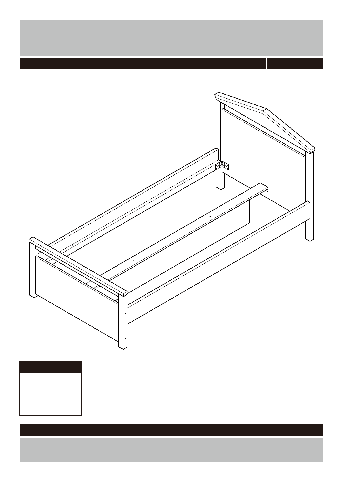
Ellie Bed Frame
Assembly Instructions - Please keep for future reference
244/7472
Dimensions
Width - 200cm
Depth - 100cm
Height - 93cm
Important - Please read these instructions fully before starting assembly
If you need help or have damaged or missing parts, call the Customer Helpline:
Argos = 0345 6400800
Version 1 Date: 05/05/14
Argos Ltd. MK9 2NW
Page 2

WARNING
IMPORTANT! KEEP FOR FUTURE REFERENCE
• This child’s bed conforms to BS8509:2008 + A1:2011 & EN 71-3
• Follow the information on the warnings appearing on the bed and do not remove the warning label.
• This product is intended for children in the age range of 7-12 years. The maximum loading is 70 kgs.
• The use of water or sleep flotation mattress is prohibited.
• Prohibit more than one person on bed and do not stand on the product.
• Do not allow children horseplay on the bed and jumping on the bed as this could cause damage
to the frame and possible risk of serious injury.
• Periodically check and ensure that the components and all assembly fastenings are in their proper
position and that care should be taken that no fittings are looses.
• Assembly to be carried out by a competent adult only.
• During assembly children should be kept away from the product due to possible risk of injury.
• Unwrap all packaging materials and place the components on top of the carton box or on clean
floor to prevent it from scratching.
• Tools not included.
• This product should only be used on firm, level ground.
• Make sure the base remains in contact with the ground.
• Not suitable for children under 4 years.
• Do not place this child’s bed near heat sources, windows, blind cords, curtain pulls, other strings or
cords and other furniture.
• Do not use this child’s bed if any part is broken, torn or missing.
The recommended mattress size is L190 x W90 cm.
•
• Place the bed tight to any wall or have a gap of 300mm between the wall and the side of the bed.
1
Page 3
Safety and Care Advice
Important – Please read these instructions fully before starting assembly
Important – Please read these instructions fully before starting assembly
• Check you have all the
components and tools listed on
the following pages.
• Remove all fi ttings from the
plastic bags and separate them
into their groups.
• Keep children and animals
away from the work area, small
parts could choke if swallowed.
• Make sure you have enough
space to layout the parts before
starting.
• Do not use this item if any
components are missing or
damaged.
• During assembly do not stand
or put weight on the product,
this could cause damage.
• Assemble the item as close
to its fi nal position (in the same
room) as possible.
• Assemble on a soft level
surface to avoid damaging the
unit or your fl oor.
• During assembly children
should be kept away from the
product due to possible risk of
injury.
• Parts of the assembly will be
easier with 2~3 people.
power drill is set on a low torque
setting.
Glue safety - Take care when using glue, please follow the advice below
Skin contact: Remove
contamination by washing with
soap and water. This procedure
should also be followed prior to
eating and drinking.
Eye contact: Rinse immediately
with clean water for 15 minutes
and seek medical advice.
If swallowed: Seek medical
advice immediately.
• To reduce
the likelihood of
damaging your
product please
ensure that your
Care and maintenance
• Only clean using a damp cloth
and mild detergent, do no use
bleach or abrasive cleaners.
• From time to time check that
there are no loose screws on
this unit.
• This product should not be
discarded with household waste.
Take to your local authority
waste disposal centre.
Handy Hints
• Assemble all parts and bolts
loosely during assembly, only
once the product is complete
should you fully tighten the bolts
• Regularly check and ensure
that all bolts and fi ttings are
tightend properly.
IMPORTANT: RETAIN THESE INSTRUCTIONS FOR FUTURE REFERENCE
• Argos Ltd. MK9 2 NW. • This product is intended for
children in the age range of
7-12 years.
• Maximum load: 70 kgs.
• Assembly of this product must
be carried out by a competent
adult.
Note: if required the next
page can be cut out and used
as reference throughout the
assembly. Keep this page with
these instructions for future
reference.
2
Page 4
If you have damaged or missing components, call the
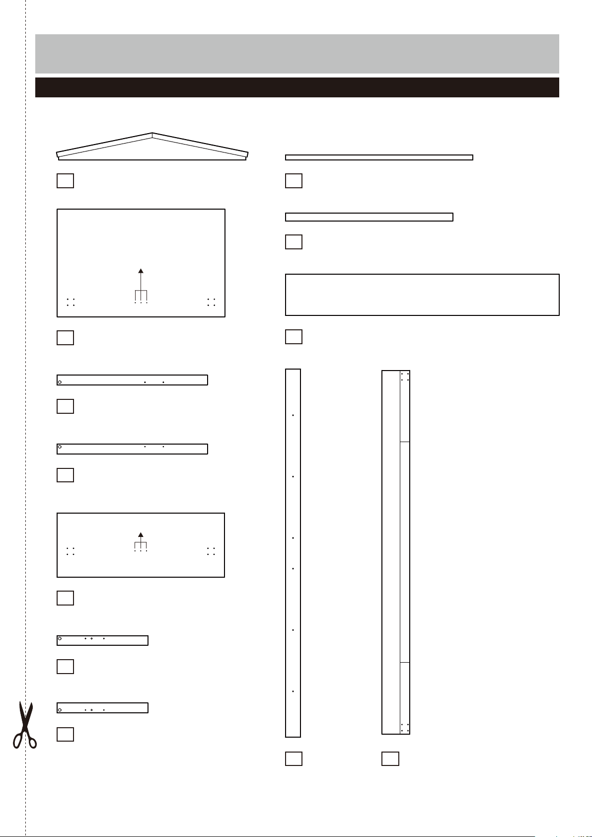
Components - Panels
Customer Helpline:
Argos = 0345 6400800
Please check you have all the panels listed below
Head board top panel (97.8 x 14.1cm)
1 Foot board top panel (97.8 x 4cm)
8
Pilot holes for
guidance only
Head board
2
3
Head board right leg
4
Head board left leg
Pilot holes for guidance only
(87.5 x 51cm)
(78.5 x 5cm)
(78.5 x 5cm)
9
Foot board support panel
10
Central support
(87.4 x 4cm)
(160 x 24cm)
Foot board
5
(87.4 x 33.5cm)
6
Foot board left leg
(47.5 x 5cm)
Foot board right leg
7
(47.5 x 5cm)
Central panel
11 Side panel x 2
(194.2 x 8cm)
12
(192 x 14.5cm)
3
Page 5

Components - Fittings
Please check you have all the fi ttings listed below
Note: The quantities below are the correct amount to complete the assembly. In some cases more fi ttings
may be supplied than are required.
A
40mm Dowel x 17
D
Screw cover x 18
G
Central board bracket x 2
J
Corner bracket x 4
M
25mm Screw x 8
B
Glue x 1
E
43mm Locking pin x 4
H
14mm Screw x 12
C
90mm Screw x 18
F
15mm Locking nut x 4
I
50mm Screw x 6
K L
15mm Screw x 32 Nut cover x 4
Tools required
Phillips screwdriver
(medium & large)
Flatblade screwdriver
(medium)
Drill
7mm Suitable drill bit
(for use with wall plug)
Ruler - Use this ruler to help correctly identify the screws
105
0 5 10 15 20 25 30 35 40 45 50 55 60 65 70 75 80 85 90 95 100
The screws length is measured from the head to the point (30mm screw shown).
110 115 120 125 130 135 140 145 150 155 160 165 170
0 10 20 30 40 50 60 70 80 90 100 110 120 130 140 150
0 1 2 3 4 5 6
Small
hammer
Ruler/tape
measure
Eye protection
(when using a
hammer or glue)
4
Page 6

Assembly Instructions
Step 1
Attaching head board
a:
Place a small amount
of Glue into the dowel
B
holes.
Insert Dowel into the
Head board .
A
2
b:
Place a small amount
of Glue into the dowel
B
holes and the joint’s
surface.
Insert Dowel into the
Head board right leg
and Head board left leg
4
.
Use Screws to fix the
Head board right leg
and Head board left leg
4
onto the Head board
panel .
Use Screw covers to
cover the screw heads.
A
3
C
3
2
D
a:
b:
D
C
D
A
C
D
A
C
A
B
2
B
A
A
A
2
A
3
2
B
B
B
4
C
C
D
A
C
D
D
c: Screw Locking pins
into the Head board
E
top panel .
Note:
as far as shown.
Do not over tighten.
Continued on next page.
5
1
Insert Locking pins
c:
E
E
1
E
Page 7

Assembly Instructions
Step 1 - continued
d: Position the Head
board top panel onto
the Head board .
Insert Locking nuts into
the Head board right leg
3
and Head board left
4
leg .
Use a screwdriver to turn
Locking nuts clockwise
to lock.
Use Nut covers to
cover the nut heads.
1
2
F
F
L
d:
F
J
L
F
3
2
1
L
F
4
Step 2
Attaching foot board
a:
Place a small amount
of Glue into the dowel
holes.
Insert Dowel into the
Foot board support panel
9
.
B
A
a:
A
A
A
A
9
B
A
A
B
Continued on next page.
6
Page 8

Assembly Instructions
Step 2 - continued
b:
Place a small amount
of Glue into the dowel
B
holes and the joint’s
surface.
Insert Dowel into the
Foot board right leg
and Foot board left leg
6
.
Position the Foot board
right leg ,Foot board
left leg and Foot
board support panel
onto the Foot board .
Use Scews to fix the
Foot board left leg
and the Foot board right
leg onto the Foot
7
board .
Use Screw covers to
cover the screw heads.
A
7
7
6
9
5
C
6
5
D
b:
D
A
B
D
C
C
A
6
5
9
A
5
B
B
7
C
C
D
D
c: Screw Locking pins
into the Foot board
E
top panel .
Note:
as far as shown.
Do not over tighten.
Continued on next page.
7
8
Insert Locking pins
c:
E
E
8
E
Page 9

Assembly Instructions
Step 2 - continued
Step 2 - continued
Place a small amount
d:
of Glue into the dowel
B
holes and the joint’s
surface.
Position the Foot board
top panel onto the
unit.
Insert Locking nuts into
the Foot board right leg
7
and Foot board left
leg .
6
Use a screwdriver to turn
Locking nuts clockwise
to lock.
Use Nut covers to
cover the nut heads.
8
F
F
L
d:
L
F
F
J
9
B
6
A
B
L
9
8
F
7
Step 3
Step 3
Attaching side panel
a:
Place a small amount
of Glue into the dowel
B
holes.
Insert Dowel into the
Side panel .
A
12
a:
B
A
B
A
B
12
A
X 2
Continued on next page.
8
Page 10

Assembly Instructions
Step 3 - continued
b:
Place a small amount
of Glue into the joint’s
B
surface.
Position the Side panels
12
onto the Head board
.
2
Use Screw to fix the
Side panels onto the
Head board .
Use Screw covers to
C
12
2
D
cover the screw heads.
b:
12
12
D
C
D
C
2
C
D
D
C
B
12
B
c:
Place a small amount
of Glue into the joint’s
B
surface.
Position the Foot board
5
onto the unit.
Use Screw to fix the
Foot board onto the
C
5
unit.
Use Screw covers to
D
cover the screw heads.
c:
D
D
C
C
12
12
5
12
B
D
D
C
C
B
9
Page 11

Assembly Instructions
Step 4
Attaching corner
brackets
Use Screws(32 pcs)
K
to fix the Corner brackets
J
onto the unit.
Step 5
J
J
KK
X 4
K K
K
Attaching central
support
a:
Use Screws(6pcs)
to fix the Central board
brackets onto the
Central panel .
G
11
b:
Use Screws
the Central support
onto the Central panel
11
.
to fix
I
10
a:
H
G
H
11
11
H
G
I
H
G
I
I
b:
I
I
I
11
Continued on next page.
10
10
Page 12

Assembly Instructions
Step 5 - continued
c:
Use Screws(6 pcs)
H
to fix the Central panel
11
onto the Head board
panel and Foot board
.
5
2
c:
2
H
11
2 5
5
11
H
Step 6
Finishing the unit
Note: With help, place
the unit in the intended
position.
Note: Before use allow
the glue to dry for 24
hours and make sure the
unit is secure.
11
Page 13

Assembly Instructions
Step 7
Additional step to fix the
slats.
Note:
supplied separately.
The slats are
Spreading the slats evenly
onto the bed frame.
Fix the slats to the
slatholders using screws
M
.
54.5mm
12.5mm
Distances are
approximate.
Assembly is complete.
M
Slats
If you need help or have damaged or missing parts, call the Customer Helpline:
Argos = 0345 6400800
12
 Loading...