

Page 1

INDUSTRIAL STYLE DESK WITH DRAWER
Assembly Instructions - Please keep for
future reference
797/1699
Dimensions
Width - 120cm
Depth - 60cm
Height - 75cm
Important
If you need help or have damaged or missing parts, call the Argos Aftersales
Helpline: 0345 640 0800
– Please read these instructions fully before starting assembly
Issue3 - 20/09/2017
Page 2
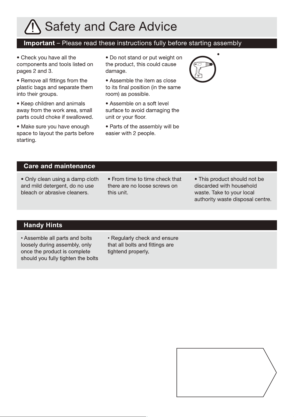
To reduce the likelihood
of damaging your product,
please ensure that your
power drill is set on a low
torque setting.
Note: if required the next
page can be cut out and used
as reference throughout the
assembly. Keep this page with
these instructions for future
reference.
1
Page 3

1 2 3
Table Top x 1 Left Leg x 1 Right Leg x 1
(120 x 60cm) (73.5 x 59cm) (73.5 x 59cm)
4 5 6
Back Board x 1 Side Board x 1 Side Board x 1
(37 x 12cm) (50.5 x 12cm) (50.5 x 12cm)
7 8 9
Supporting Bar x 2 Supporting Bar x 1 Drawer Front x 1
(25cm) (56 x 13.5cm) (40 x 10cm)
10 11 12
Drawer Side Board x 1 Drawer Side Board x 1 Drawer Back Board x 1
(40 x 8cm) (40 x 8cm) (32.1 x 8cm)
13 14
Drawer Bottom Board x 1 Cross Bar x 2
(33 x 39.5cm) (111cm)
Page 4
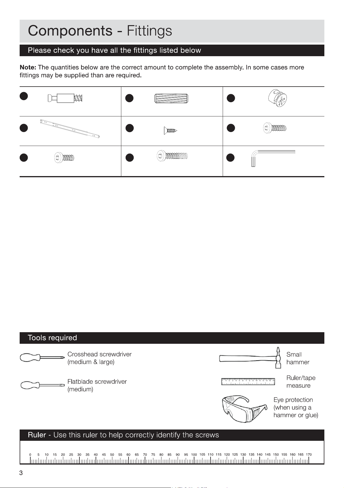
A
B C
Camlock Screw(22mm) x 18
Runner(390mm) x 2
G
G
Bolt (M6 x 12mm) x 13
Dowel (Ø8 x 30mm) x 8 Camlock Nut(Ø15mm) x 18
E
Screw (Ø3.5 x 14mm) x 12
G
H
Bolt( M6 x 30mm) x 6
FD
Bolt( M6 x 25mm) x 2
G
I
Allen Key(62 x 6mm) x 1
Page 5

Assembly Instructions
Assembly Instructions
Step 1
a: Insert camlock nut C x 6
C
into back board 4 .
b: Insert camlock nut C x 2
C
into side board 6 . Insert
camlock screw A
and
into
C: Insert camlock nut C x 2
side board 6 . Attach
runner D to side board 6
D1
by using screw E x 3 .
A
x 2
B
1x lewod
E
C
into side board 5 . Insert
camlock screw A x 2
and
into
side board 5 . Attach
runner D to side board 5
D1
by using screw E x 3 .
A
B
1x lewod
E
Step 2
a: Attached side board 5 & 6
to back board 4 .
b: Use a screwdriver to turn
camlock nut clockwise to
lock.
a: b: c:
C
E
E
D1
C
C
C
C
A
A
B
A
E
E
D1
C
A
C
A
B
Step 3
a: Insert camlock screw A x 6
into table top 1 .
b: Insert dowel B x 6 into
B
table top 1 .
A
Step 4
a: Attach assembled part to
table 1 .
b: Use a screwdriver to turn
camlock nut clockwise to
lock.
C
A
A
B
B
A
B
B
B
A
A
B
A
C
4
Page 6

Assembly Instructions
Step 5
Attach supporting bar 8 to
the assembled part by using
F
bolt F x 2.
Step 6
Attach cross bar 14 to left
leg 2 and right leg 3 by
using bolt G x 4 for each.
G
I
F
G
G
G
G
Step 7
Attach the assembled leg to
the table top 1 by using bolt
H
H x 6.
Step 8
Attach supporting bar 7 & 8
to the assembled part by
using screw G as show.
G
H
H
H
H
H
H
G
7
G
G
G
G
G
7
5
Page 7

Assembly Instructions
Step 9
a: Insert camlock nut C x 2
and camlock screw A into
drawer side 10
b: Repeat a for drawer side 11
c: Insert camlock nut C x 4
into drawer back 12
C
A
C
Step 10
a: Attach drawer side 10 &
11 to drawer back 12
b: Use a screw driver to turn
camlock nut clockwise to
lock
A
C
C
A
C
C
A
C
C
Step 11
a: Insert the drawer bottom 13
to the assembled drawer.
Step 12
a: Insert camlock screw A x 4
to drawer front 9 .
b: Attach drawer front 9 to
assembled part.
A
A
A
6
Page 8

Assembly Instructions
Step 13
a: Attach runner to drawer
Side 10 by using screw
E
E x 3
b: Repeat a for drawer side 11
D2
E
E
D2
E
D2
E
E
E
Step 14
a: Insert the drawer
Assemble is complete.
7
 Loading...